


Wiring diagram for a battery disconnect.
Thread Starter
Joined: Mar 2003
Posts: 593
Likes: 0
From: Whiteland, Indiana
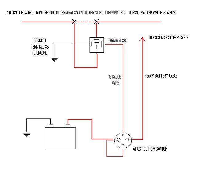
I am thinking about doing this, and did a search. I am still confused. Here is a diagram I found. https://ls1tech.com/forums/attachmen...disconnect.gif
What I have learned so far is that I will need to have my alt. rebuilt to push 145 amps. I will need a 4 post cut off switch like the Moroso part # MOR-74101.
What I need to know is what gauge wire to run and to where? I keep reading 2 gauge.. but 2 gauge to what? What PCM wire do I need to connect to the disconnect switch on a '99 Camaro? I have read so many different ways to do this. Yes this is a street car, but I am certain there has to be a way to do this and not lose any driveability.
The diagram would help a ton if it specified what gauge wire to use and where, and what PCM wire to connect to.
Thanks.
Seems awful complicated to me... All I did was rewire the alternator output wire directly to the positive terminal of the battery. When the switch was pushed, power from the battery and alternator are cut to the PCM and the car shuts off. 2ga from the alternator to the battery should be fine - not sure why you need 145amp alternator...
Thread Starter
Joined: Mar 2003
Posts: 593
Likes: 0
From: Whiteland, Indiana
Even with a 145A alternator 2ga should be more than enough from the output to battery. With your underdrive pulley it probably isnt a bad idea to step up to a higher output alternator but if youre not running huge draw (fans, big pump, etc) the stocker should be able to handle it. Mine worked fine when it was just a bolt on car.
I used 2 ga from battery to switch, and switch to starter. Then 6 ga from starter to junction block on passenger fender. Also 6 ga from stock alternator directly to positive post on battery. Starts fine and switch kills everything. Just make sure your connections are good, I crimped and soldered mine. Aslo make sure you have plenty of grounds.
I am thinking about doing this, and did a search. I am still confused. Here is a diagram I found. https://ls1tech.com/forums/attachmen...disconnect.gif
What I have learned so far is that I will need to have my alt. rebuilt to push 145 amps. I will need a 4 post cut off switch like the Moroso part # MOR-74101.
What I need to know is what gauge wire to run and to where? I keep reading 2 gauge.. but 2 gauge to what? What PCM wire do I need to connect to the disconnect switch on a '99 Camaro? I have read so many different ways to do this. Yes this is a street car, but I am certain there has to be a way to do this and not lose any driveability.
The diagram would help a ton if it specified what gauge wire to use and where, and what PCM wire to connect to.
Thanks.
What I have learned so far is that I will need to have my alt. rebuilt to push 145 amps. I will need a 4 post cut off switch like the Moroso part # MOR-74101.
What I need to know is what gauge wire to run and to where? I keep reading 2 gauge.. but 2 gauge to what? What PCM wire do I need to connect to the disconnect switch on a '99 Camaro? I have read so many different ways to do this. Yes this is a street car, but I am certain there has to be a way to do this and not lose any driveability.
The diagram would help a ton if it specified what gauge wire to use and where, and what PCM wire to connect to.
Thanks.

11 Second Club
Joined: Aug 2005
Posts: 804
Likes: 0
From: Tampa, FL
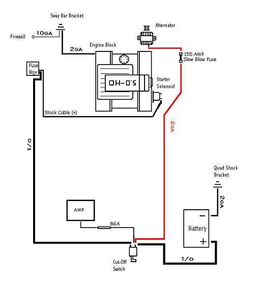
Man, those diagrams seem to over complicate things. Maybe its just my simple minded thinking. Anywho, this is the dummy down version of a wiring diagram that I used. This passes NHRA specs.
oh btw, Captain InsaneO- LOL. Love that name. Good choice.
Disregard the amp box section if you don't have one.
oh btw, Captain InsaneO- LOL. Love that name. Good choice.
Disregard the amp box section if you don't have one.
Trending Topics
LS1 Tech Stories
The Best V8 Stories One Small Block at Time

Topdon ONE vs. Artidiag 800 BT2: Which is the Diagnostic Tablet For You?
Pouria Savadkouei
Gas Monkey Built a 6-Wheel Ferrari Testarossa With a Corvette LT4 Engine
Verdad Gallardo
7 Most Reliable High-Performance Engines GM Has Ever Built
Verdad Gallardo
Amazing '71 Camaro Restomod Is Modern Muscle Car Under the Skin
Verdad Gallardo
6 Common C5 Corvette Failures and What's Involved In Repairing Them
Pouria Savadkouei
Retro Modern Bandit Pontiac Trans AM Comes With Burt Reynolds' Autograph
Verdad Gallardo
Top 10 Greatest Cadillac V Series Performance Models Ever, Ranked
Pouria Savadkouei
Top 10 Most Powerful Chevy Trucks Ever Made!

Hennessey's New Supercharged Silverado ZR2 Has 700 HP
Verdad Gallardo yes i have the 4 post switch. also with an amp i would think you would want to hook it up to the battery itself or the battery side of the switch.
Thread Starter
Joined: Mar 2003
Posts: 593
Likes: 0
From: Whiteland, Indiana
So depending on which diagram I choose determins if I go with a 2 post or a 4 post disconnect switch. I assume one disconnect switch is not better than the other?
Thread Starter
Joined: Mar 2003
Posts: 593
Likes: 0
From: Whiteland, Indiana
Ok after more research I have found that I need to decide which battery disconnect switch to use. A push/pull type (With the rod), or one with an "on off" lever. It appears the drawback of the "on off" one is that the rear panel may crack, and after looking at the Flaming River unit, I don't see how it would mount securely to the rear panel.
I don't really like the push pull rod type. They stick out too far, and I have an amp rack that mounts to the back of the hatch, so mounting it anywhere other than underneath the pass. side tail light is not an option.
Are there any other drawbacks to using the lever type? Has anyone mounted a lever type switch in the rear panel as I described, and if so have you had any issues?

Man, those diagrams seem to over complicate things. Maybe its just my simple minded thinking. Anywho, this is the dummy down version of a wiring diagram that I used. This passes NHRA specs.
oh btw, Captain InsaneO- LOL. Love that name. Good choice.
Disregard the amp box section if you don't have one.
oh btw, Captain InsaneO- LOL. Love that name. Good choice.
Disregard the amp box section if you don't have one.
I like this plan. Looks simple.