
th350 transmission
 11-25-2015, 10:07 PM
#1
Teching In
Thread Starter

Join Date: Nov 2015
Posts: 6
Likes: 0
Received 0 Likes
on
0 Posts
dum #1dumdum
dumToday, 08:08 PM
Benjamin R. Sims
CF Beginner
dum
Join Date: Nov 2015
Posts: 1
dumth350 transmission
Two quick questions. First of all; there isn't any end play in the front shaft after i rebuilt it. The u-tube videos I watched said to measure the end play and it needed to be between 25- to like 40 thousandths. Everything spins great and feels good. I did all new bushings, rings, seals, steels and frictions. Does it have to have end play? Or is everything supposed to be tight when it's all new? Could my new bushings just be too tight to let the shaft slip forward and backward?Secondly, when i torqued the pump, one of my bolts broke. Will it leak there? I hate to remove everything to ease - out one bolt if it won't leak. I would think it wouldn't leak because the bolt is still in there. Any help would be appreciated.
 11-26-2015, 12:30 AM
#2
TECH Fanatic

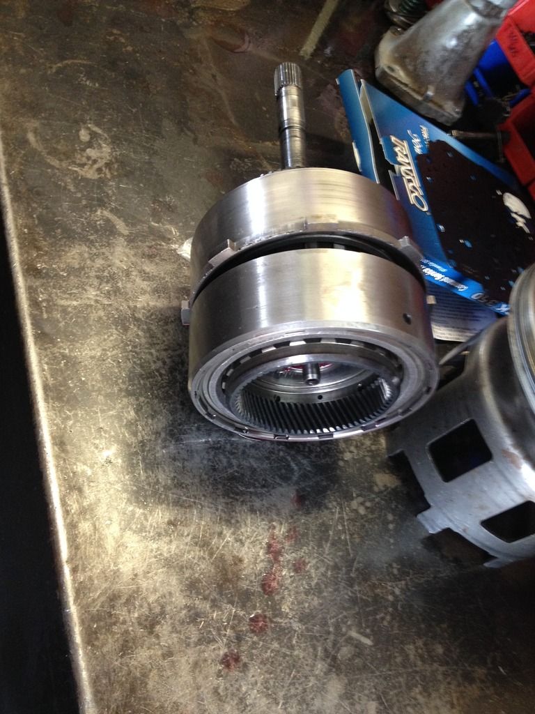
Is the trans sitting with the Input Shaft pointing up? If so, You need mechanical leverage to lift the Direct & Forward drums up to check Endplay.
There is a hole in the Input Shaft right above the Stator Support, I use a Pocket Screwdriver, Insert the tip of the screwdriver in the hole, Pry up against the Stator Support, This will lift the TWO heavy cast iron drums.
There is a hole in the Input Shaft right above the Stator Support, I use a Pocket Screwdriver, Insert the tip of the screwdriver in the hole, Pry up against the Stator Support, This will lift the TWO heavy cast iron drums.
11-26-2015, 02:17 AM
#3
Teching In
Thread Starter
Join Date: Nov 2015
Posts: 6
Likes: 0
Received 0 Likes
on
0 Posts
Didn't think about that. Thank you. Unfortunately, I am going to have to pull the pump and forward and direct drums anyway. I was cleaNing up my workbench and found the small snapring that goes on the rear shaft on top of the front planet. Oops. I don't see how any of that could move once the forward clutch is installed, but am too afraid not to take it apart too install the little thing. What is your opinion on that pump bolt? I am going to try my best to get it out and replaced, but you know what a pain it is to use an ease - out.
11-26-2015, 08:18 AM
#4


On the TH350 with every metal thrust washer used you will need .004" - .005" clearance per washer used. The plastic thrust washer needs .001" - .003" per washer used. The less metal thrust washers and the more bearings (to replace the thrust washers) and or plastic thrust washers used instead allows for less total end clearance. Metal thrust washers need more clearance for lubrication. The later TH350's used more plastic thrust washers and bearings. The later front pump used a bearing instead of the thrust washer to go against the direct drum and had a much better support area for the direct drum bushing to ride on. The Buicks used a bearing on the front planet instead of the thrust washer as in other TH350's. I hope this helps.
11-26-2015, 03:53 PM
#5
TECH Addict

Check the endplay as clinebarger suggested before pulling the pump, that way you can make adjustments while you’re in there. If the broken bolt is at the top of the bellhousing you may by okay. If the bolt is at the bottom I would remove it.
11-27-2015, 05:37 PM
#7
Teching In
Thread Starter
Join Date: Nov 2015
Posts: 6
Likes: 0
Received 0 Likes
on
0 Posts
Update on my project. I'm pretty sure the last friction in the direct drum was not engaged with the forward drum and kept the two apart the thickness of the clutch the first time I put it together. After taking it apart, installing the small snap ring and replacing the pump bolt washers, it had the perfect amount of end play. Also, as far as the broken pump bolt, I was lucky enough that there were two threads protruding from the case, so I was able to remove it easily with a pair of pliers. My only question now is; my new governor gear didn't have a hole in it for the keeper pin. I'm assuming this is normal because it would be nearly impossible to keep it lined up while you press it in. Does anyone know what size hole I am supposed to drill through it?
Trending Topics
11-27-2015, 08:50 PM
#8
TECH Fanatic
Probably the smallest drill bit that will chuck-up in your drill, The pin needs to press into the plastic gear.
You do not have to "Lace" the Direct or Forward clutches in the case on a TH350...
With the Forward Drum on the bench, Lace the Direct Drum onto the Forward Drum, Lay the 2 Drums on their side, Lace the Front Planet Hub into the Forward Clutches, Rotate the Trans case so the Valve Body surface faces up, Stab the Forward Drum, Direct Drum, & Forward clutch Hub in the case at the same time.
 11-27-2015, 11:14 PM
#9
Teching In
Thread Starter
Join Date: Nov 2015
Posts: 6
Likes: 0
Received 0 Likes
on
0 Posts
That is what I ended up doing. The first time I tried to lace them independently and I think that is how I ended up with an unengaged clutch. It was a whole lot easier to put them in together. Thanks for all of your help. I'll just have to find time to put it in the truck to find out how well (or poorly) my first build went. Everything felt right though, so hopefully it will go in and operate smoothly. The only disappointing part I can see right now is the fact that my case has a stripped thread where the mount bolts on. I didn't know it until I installed the mount. I bought the case from a "core buyer" because my original case had too much center support lug damage. I was so concerned with checking out the inside that I never thought to look at the mount holes. The other side holds well, but I am still going to try to take the whole unit out to my father-in-laws shop and tap it out I guess.
11-29-2015, 01:34 AM
#11
Once the plastic gear is pressed into the governor, the drill bit to use is a .125". Install the pin and peen over the pin hole carefully. Blow off everything with high pressure air (80 - 150 psi.) and make sure the valve moves freely in the governor itself.