When you click on links to various merchants on this site and make a purchase, this can result in this site earning a commission. Affiliate programs and affiliations include, but are not limited to, the eBay Partner Network.
That works fine. I Did them like that in the 90's. People would say it won't stop right and try to stall. But like you said it'll be out of 4th long before you stop.
There are a few different ways to wire it. Some pressure switches are normally open some normally closed. Wire it accordingly.
Do Not put a check ball in the tcc snout. Some people see that as simple but it'll lock up before 4th.
I always wired mine through a three position toggle switch after key on power. This way lock up could be disabled, turned off, or turned on in other gears.
Ok now I'm not so sure.
You need to pull the pan and start from scratch, you know this right?
You don't need the location letters of any terminals, just run one from key on power to the plug, then from the inside of the plug to one side of the pressure switch. If normally open, run a wire from the other side of the pressure switch to the tcc solenoid. Then ground the other side of the solenoid.
If you have a one terminal pressure switch theres another way. If the switch is normally closed theres yet another way.
There are 20 or more factory configurations, some have a temperature switch also. Some have 3rd gear switches. You need to take the pan off or pull your hair out guessing.
Good luck.
Last edited by FourthGenCamaro; 04-22-2018 at 11:07 AM.
Yeah, I couldn't get a "click", no matter what I did.
That's the problem I've had looking at all the wiring "diagrams". One person shows the wiring plug-with the locking clip pointing towards the front (which is the way mine plugs in), and one shows it pointing away from the case to the left.
Then some show the wires A, B, C, D clockwise from the outer-forward position (again, which I have been going by) , then I see one that goes the opposite, starting from the inner-forward position, going counter-clockwise!. ARGHH!
You've got to ask yourself, why would it click?
It's not in 4th gear, the pressure switch is open or otherwise not allowing voltage to the tcc solenoid.
Wouldn't it be just as simple to get the kit made by B&M that is speed activated and wire it according to their instructions. It's also adjustable so you can set it at a speed high enough that you will always be in OD before it locks the convertor..
I stuck to the word simple.
Really all thats needed is already there. Just need to pull the pan and reconfigure the wiring, all it costs is a few wire connectors.
A B&M kit will work, still need to pull the pan and configure the wiring.
By design the switch will not see fluid pressure until 4th is applied so it's impossible to apply lockup in a lower gear.
I haven't done anything yet. I was just doing the following per Monster Transmissions:
LET'S TEST THE LOCKUP SOLENOID
First we will verify if the transmissions lockup solenoid is functioning and if it's a 2 wire or a 1 wire solenoid.
1. Connect the transmission connector plug to the transmission plug on the driver side and be sure it is plugged in securely.
2. Apply a 12V+ voltage to the loose pigtail of the connector plug.
3. (A)You should see a small spark when connecting and you will hear a faint "click" inside the transmission. This is an indicator you have a functioning, 1 wire solenoid and can cut and remove the eyelet ground lead on the transmission connector plug. If you don't hear the click, ground the lead with the eyelet.
4. (B) If it now clicks, you have a 2 wire solenoid and must ground the lead permanently.
And, so far... no "click"
Again, if it clicked during this test you would have lock up right when it shifted to 2nd.
It's not clicking because theres a pressure switch that needs to close so power can have a path to the lock up solenoid. Some 700's have 2nd 3rd and 4th pressure switches and a temperature switch.
I'll change my advice, get a b&m kit and follow the instructions. You could do it for free in a few hours with what you have but you don't seem to take advice well. Pay for a kit and have at it.
Jays SSZ28: Don't know what year, it was built for me. First exposure to OD trans.
FourthGenCamaro: Just trying to understand how the lockup works. I am usually open for suggestions, but I don't/can't just fork out $200+ without checking all avenues.
Anyway, I did pull the pan and took a few pics. Still doesn't help much, as I can't find documentation that can tell/show me what I have.
I did find one picture that was titled 3rd 4th lockup. Sorta looks similar to what I have. Thanks...
Mine is the first pic, and the sample I found is second.
In your picture the switch on the left is for 4th. It should ground when pressurized. Check with a meter to make sure it's normally open.
So Leave the switch on the left, leave the tcc solenoid. Take everything else out. Run key on 12 volts right to one wire on the tcc solenoid, run the other tcc solenoid wire to the switch on the left.
If the tcc solenoid has one wire you need to get a two wire one.
Wired as said above you have 12 volts at the tcc solenoid, when it hits 4th the switch closes and grounds the circuit and energizes the tcc solenoid. Sounds too easy doesn't it?
OK, since I can't find anything online to show what is what, I'll guess.
The switch with the green connector is 4th gear?
The switch with the two orange connectors is 3rd gear?
The shiny thing with the black connector is a temp switch? ?
In my diagram, the switch I will use in the 4th gear port is: "ACDelco 8643710 GM Original Equipment Automatic Transmission Clutch Oil Pressure Switch"?
Jay,
It sounds like you've described what is shown in the pic of the wiring "kit" in the pic below, with the black connector going to what I thought was the temp switch?
All correct.
You're not using what you have already?
I don't know about that switch you gave the part number to or that wiring and tcc solenoid.
There are many parts that can be used to make it function the same way. A quick google search doesn't say if that switch is normally open or closed. Most likely normally open.
The problem with the tcc solenoid and wiring you show here is that it gets ground from the external plug.
I can tell you how to wire it, you just need to tell me what parts you are going to use.
Jay,
I've asked Summit Racing and Scoggin-Dickey to tell if the switch is "normally open" or not, but no response yet.
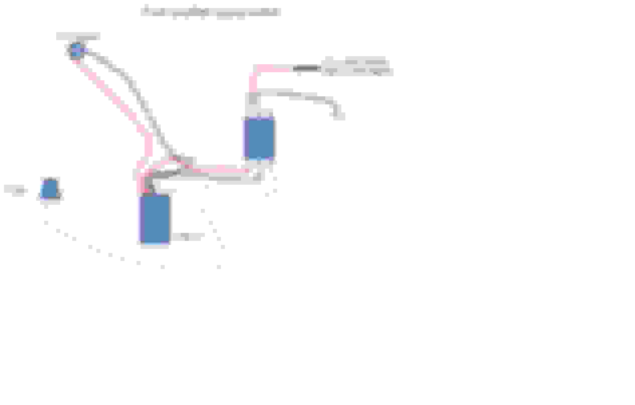
I'm including 2 diagrams. The first is the current internal wiring for my trans. and the second is a diagram of a 4th gear lockup that I found (somewhere) on the internet.
The second looks like it should work(?), but I don't know... (he used a toggle sw. to trigger the 12v to the internals).
Anyway, assuming the switch in question is "NO", I think my original diagram for external wiring should be OK, right?
As far as the internal wiring, I just want to lockup when it hits 4th gear. I'm probably oversimplifying it, but it seems like everything should be there, just a matter of cutting the third gear sw. out of the wiring and rerouting the wires to the right place(s). (how's that for dancing around the problem?).
Q1. In the two pics, below, do the 4th gear sw. and the 4th gear (external) port both get pressure at the same time when shifting into 4th gear? (seems like it should be obvious, but...)?
Q2. In the final diagram, above, it shows the 4th gear sw. with two prongs. Can I switch the 3rd and 4th switches in order to accomplish this?
This would use the 4th gear sw. as a "plug" in the 3rd gear sw. position, and the temp sw. would also perform as a "plug", no wires connected to either one.


 04-21-2018, 12:58 PM