
kst8engineer - '71 Chevelle LS1/T56 build thread

 03-17-2009, 11:14 PM
#62
All I can say is..... Been there, Done That., all of that ! ! LOL.. Look like you been busy.. good going.. !
Yeah, it was a shoe horn fit with the F-body pan. That was one reason I when to a CTS-V pan.
With the F-body pan, it will be very close fit, like 1/2" to 3/4" around the pan and cross memeber, maybe a finger width. And about an 1" between the firewall and the passenger side head.
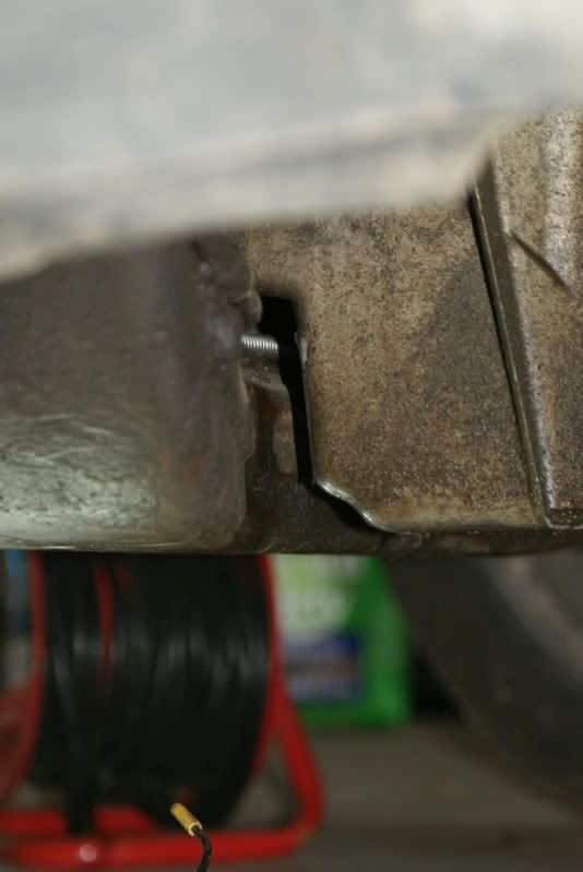
Here is a picture of the notch for the AC that I did.
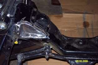
The AC / HVAC box will be close, took the cover and cut into it and used filberglass to reshape it so that it would not be as far out from the firewall.. it was not much, but it helped. I also use some Coolmax sheet / tape on the box to insultate it some from the header heat.
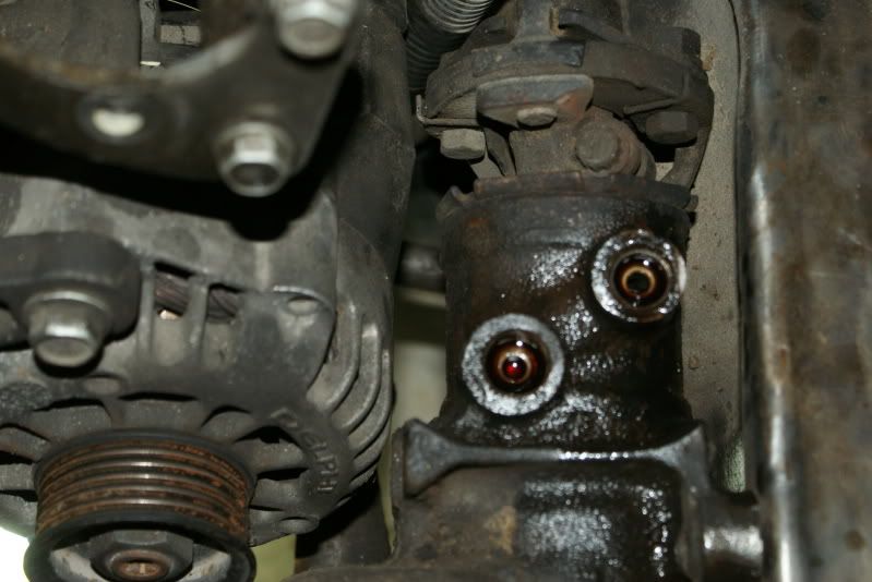
I did grind the Alternator rear bracket to clear the rag joint as well as the steering box near the pulley.
Yeah, it was a shoe horn fit with the F-body pan. That was one reason I when to a CTS-V pan.
With the F-body pan, it will be very close fit, like 1/2" to 3/4" around the pan and cross memeber, maybe a finger width. And about an 1" between the firewall and the passenger side head.
Here is a picture of the notch for the AC that I did.
The AC / HVAC box will be close, took the cover and cut into it and used filberglass to reshape it so that it would not be as far out from the firewall.. it was not much, but it helped. I also use some Coolmax sheet / tape on the box to insultate it some from the header heat.
I did grind the Alternator rear bracket to clear the rag joint as well as the steering box near the pulley.
03-18-2009, 07:41 AM
#63
On The Tree
Thread Starter
iTrader: (6)

Join Date: Mar 2006
Location: Kansas
Posts: 192
Likes: 0
Received 0 Likes
on
0 Posts

I just decided I'd rather wait and see what it looked like in the trial fit before I started modifying. In some respects, I like the idea of modifying the A/C bracket to relocate the compressor rather than notching the frame, but since the heater hose fittings are directly above the compressor, I don't know if this is possible. I might research other A/C bracket options before I notch the crossmember.
03-18-2009, 07:52 AM
#64
On The Tree
Thread Starter
iTrader: (6)
Join Date: Mar 2006
Location: Kansas
Posts: 192
Likes: 0
Received 0 Likes
on
0 Posts
At a quick glance, my clearances look very similar to yours. I'm planning to go with an aftermarket underdash A/C unit, so that will free up the space on the firewall.
All I can say is..... Been there, Done That., all of that ! ! LOL.. Look like you been busy.. good going.. !
Yeah, it was a shoe horn fit with the F-body pan. That was one reason I when to a CTS-V pan.
With the F-body pan, it will be very close fit, like 1/2" to 3/4" around the pan and cross memeber, maybe a finger width. And about an 1" between the firewall and the passenger side head.
The AC / HVAC box will be close, took the cover and cut into it and used filberglass to reshape it so that it would not be as far out from the firewall.. it was not much, but it helped. I also use some Coolmax sheet / tape on the box to insultate it some from the header heat.
I did grind the Alternator rear bracket to clear the rag joint as well as the steering box near the pulley.
Last edited by kst8engineer; 03-18-2009 at 01:08 PM. Reason: correction

 03-19-2009, 08:07 AM
#66
On The Tree
Thread Starter
iTrader: (6)
Join Date: Mar 2006
Location: Kansas
Posts: 192
Likes: 0
Received 0 Likes
on
0 Posts
By the way, nice Chevelle! Orange is one of the color possibilities I'm considering for mine as well.
03-19-2009, 11:24 PM
#67
On The Tree
Thread Starter
iTrader: (6)
Join Date: Mar 2006
Location: Kansas
Posts: 192
Likes: 0
Received 0 Likes
on
0 Posts
I messed around with the position of the engine a little more this evening. I noticed that the engine was sitting slightly offset toward the driver's side, so I shifted it over to the center, and it actually created a slight amount of clearance between the alternator and the rag joint and steering box.
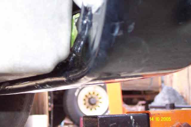
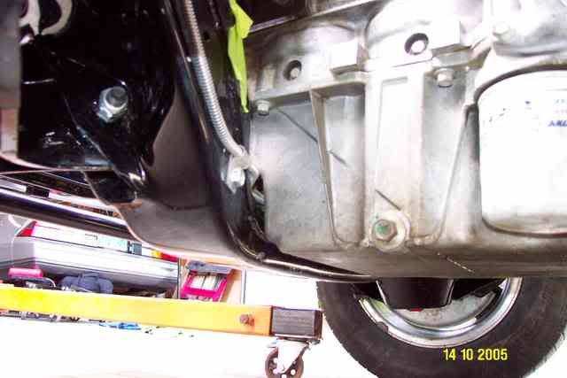
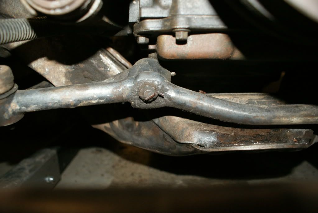
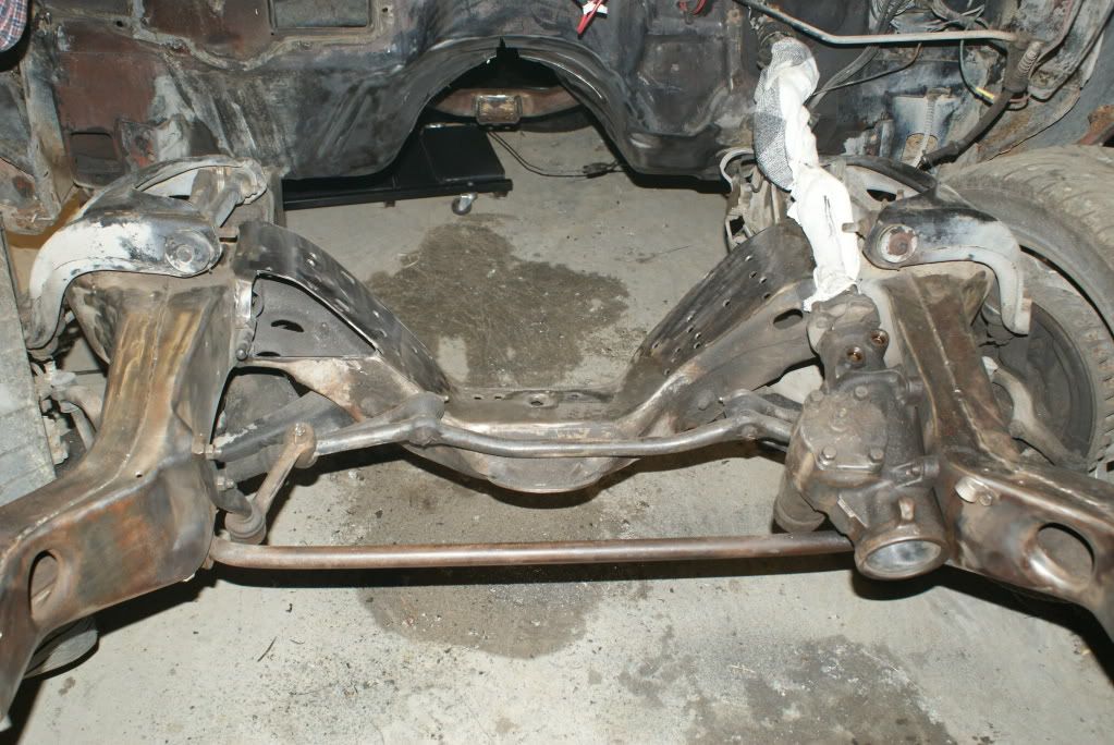
I think it's fairly well centered left-to-right as it sits right now. I also checked the clearance between the steering centerlink joints and the oil pan, and of course, it didn't clear as you move toward full steering lock in either direction. I tried adding the load plates that came with the Energy Suspension engine mounts as an extra spacer, but it still wasn't enough to prevent the centerlink joints from contacting the pan. I suppose the next thing to try is a pair of additional 1/4" spacers (compared to the load plates which are only 1/8" or so thick). The pic below shows the current clearance under the pan.
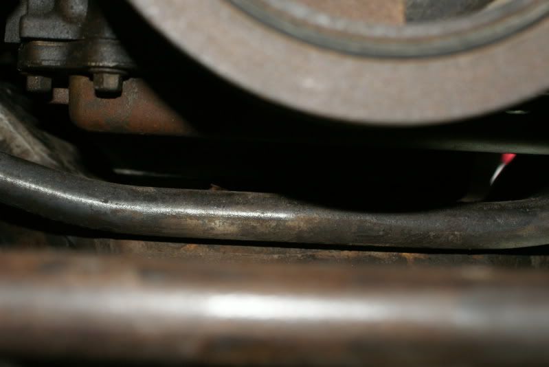
Here's a pic showing the clearance between the oil pan and crossmember right now. There's not a lot of extra room, but I think it's enough.
I think it's fairly well centered left-to-right as it sits right now. I also checked the clearance between the steering centerlink joints and the oil pan, and of course, it didn't clear as you move toward full steering lock in either direction. I tried adding the load plates that came with the Energy Suspension engine mounts as an extra spacer, but it still wasn't enough to prevent the centerlink joints from contacting the pan. I suppose the next thing to try is a pair of additional 1/4" spacers (compared to the load plates which are only 1/8" or so thick). The pic below shows the current clearance under the pan.
Here's a pic showing the clearance between the oil pan and crossmember right now. There's not a lot of extra room, but I think it's enough.
03-20-2009, 12:38 PM
#68
On The Tree
Thread Starter
iTrader: (6)
Join Date: Mar 2006
Location: Kansas
Posts: 192
Likes: 0
Received 0 Likes
on
0 Posts
Looking at options for my A/C setup, I've seen a few LSx a/c compressors that have fittings which enter/exit the side of the compressor rather than the rear (like the f-body compressor does). I'm just wondering if there's a compressor like this from another LSx application that could be used to solve the crossmember clearance issue.
For example, here's a compressor from an '04 GTO. In the pic, you can see how the lines enter/exit the side of the compressor rather than the rear.
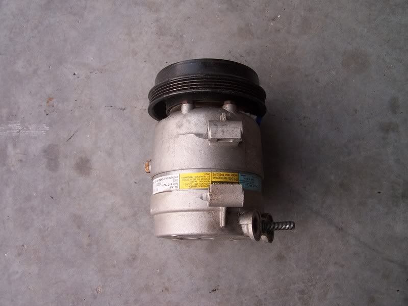
It also seems like I remember hearing that somebody (maybe S&P?) was doing a hybrid compressor where they use the front half of an F-body compressor with the back half of a (Vette?) compressor to get around this issue. Anybody have any experience or suggestions along these lines?
For example, here's a compressor from an '04 GTO. In the pic, you can see how the lines enter/exit the side of the compressor rather than the rear.
It also seems like I remember hearing that somebody (maybe S&P?) was doing a hybrid compressor where they use the front half of an F-body compressor with the back half of a (Vette?) compressor to get around this issue. Anybody have any experience or suggestions along these lines?
03-20-2009, 09:12 PM
#70
On The Tree
Thread Starter
iTrader: (6)
Join Date: Mar 2006
Location: Kansas
Posts: 192
Likes: 0
Received 0 Likes
on
0 Posts
https://ls1tech.com/forums/conversio...n-turbo-2.html
This guy got his mounted with the factory compressor.. and Fbody pan
This guy got his mounted with the factory compressor.. and Fbody pan
03-20-2009, 11:54 PM
#71
On The Tree
Thread Starter
iTrader: (6)
Join Date: Mar 2006
Location: Kansas
Posts: 192
Likes: 0
Received 0 Likes
on
0 Posts
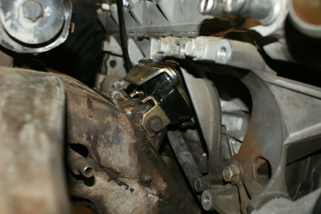
In an attempt to improve my steering centerlink / oil pan clearance, I added the Energy Suspension load plates in addition to the adapter plates and 1/4" spacers. At full right lock, there's no problem at all. At full left lock, the joint on the passenger side of the centerlink just barely contacts the oil pan. The pictures shown below are at full left lock.
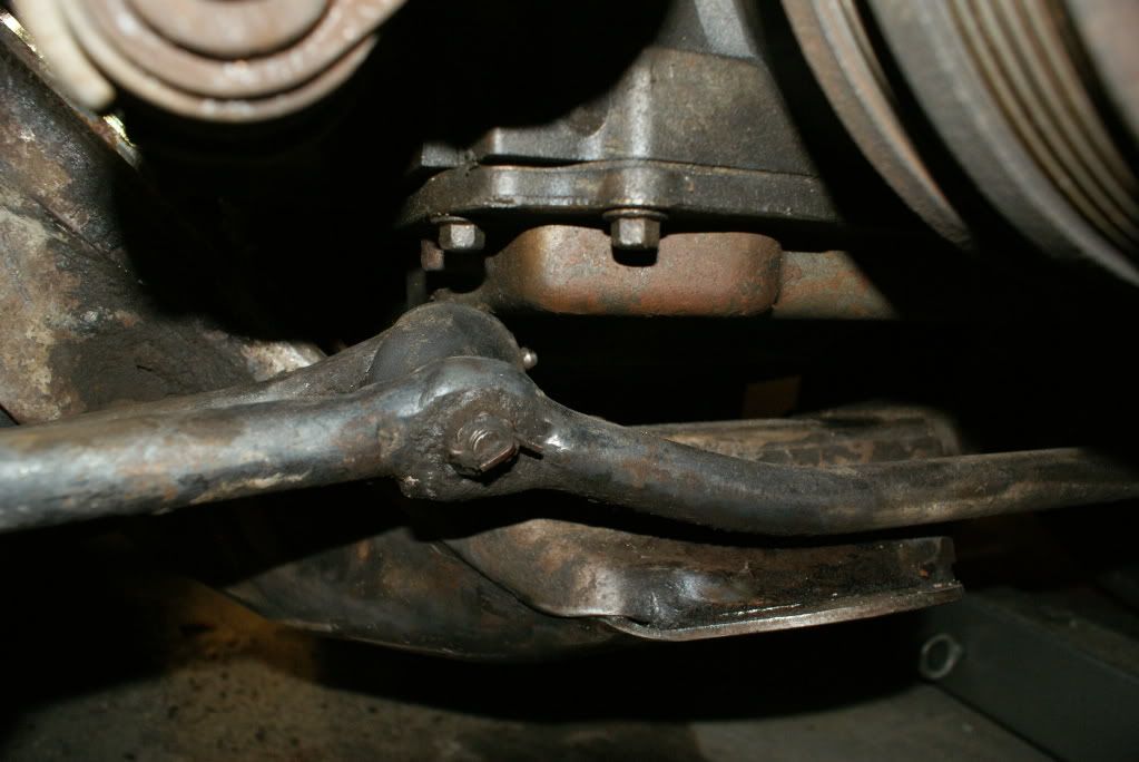
I chatted with Bczee about it, and he and I both agreed that adding some adjustable steering stops would be the best solution. The amount of turning ability lost would very minimal, and it will prevent me from having to raise the engine any higher than necessary.
I chatted with Bczee about it, and he and I both agreed that adding some adjustable steering stops would be the best solution. The amount of turning ability lost would very minimal, and it will prevent me from having to raise the engine any higher than necessary.
03-21-2009, 07:02 PM
#72
On The Tree
Thread Starter
iTrader: (6)
Join Date: Mar 2006
Location: Kansas
Posts: 192
Likes: 0
Received 0 Likes
on
0 Posts
I modified the transmission crossmember today (flipped the tab and welded it back on), and I've got the engine sitting at 2.5 degrees back tilt. I noticed that the reverse lockout on the T-56 is hitting the driver's side of the tunnel and is pushing the tranny toward the passenger side. I'm not sure whether to mod the tunnel for this, or to eliminate the reverse lockout.
Here are some pics of today's progress:
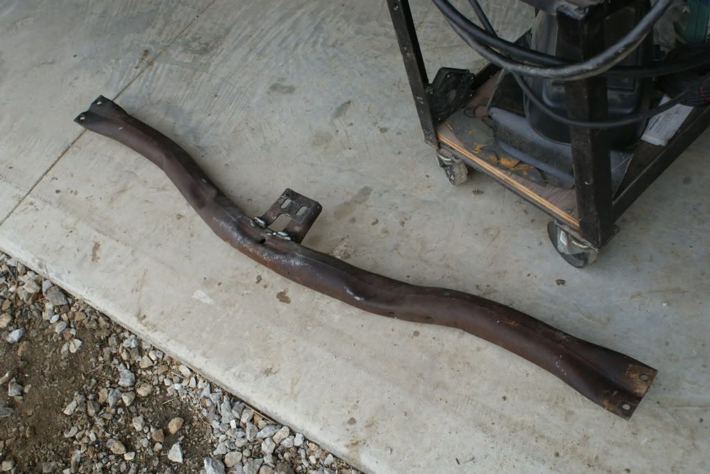
Here are some pics of today's progress:
03-22-2009, 11:47 PM
#73
On The Tree
Thread Starter
iTrader: (6)
Join Date: Mar 2006
Location: Kansas
Posts: 192
Likes: 0
Received 0 Likes
on
0 Posts
I got home from church this afternoon and decided to do a trial fit on the Edelbrock headers, and they seem to fit very well.
I dropped the passenger side header in from the top. I figured out that the starter must be removed before installation, or it won't fit. I think after the header is in place, but before the bolts are tightened down, you could swing the header outward a little to make reinstallation of the starter a little easier. Once it's in place, everything seems to fit very well.
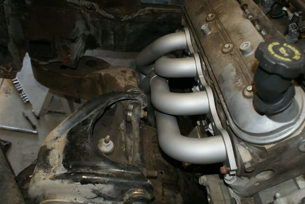
I brought the driver's side header up from the bottom. As you can see in the picture below, I taped an old sock around the lower end of the steering column so that I wouldn't scratch up the finish of the headers. Although the Edelbrock header coating basically looks like silver paint, it does seem to be pretty durable. I accidentally scraped the headers up against the frame in a few places and thought I had scratched them, but the marks rub off easily, and the finish was undamaged. I don't have any clearance issues on this side either.
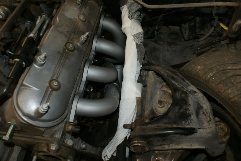
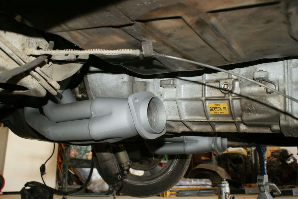
I've got a good amount of clearance between the header collector and the floorboard as well (probably about 2"), but I don't think they're going to hang low enough to cause a clearance problem.

I dropped the passenger side header in from the top. I figured out that the starter must be removed before installation, or it won't fit. I think after the header is in place, but before the bolts are tightened down, you could swing the header outward a little to make reinstallation of the starter a little easier. Once it's in place, everything seems to fit very well.
I brought the driver's side header up from the bottom. As you can see in the picture below, I taped an old sock around the lower end of the steering column so that I wouldn't scratch up the finish of the headers. Although the Edelbrock header coating basically looks like silver paint, it does seem to be pretty durable. I accidentally scraped the headers up against the frame in a few places and thought I had scratched them, but the marks rub off easily, and the finish was undamaged. I don't have any clearance issues on this side either.
I've got a good amount of clearance between the header collector and the floorboard as well (probably about 2"), but I don't think they're going to hang low enough to cause a clearance problem.
03-23-2009, 12:41 AM
#74
Looks everything is coming along well.. My headers hang down about the same, I have hit them on large speed bumps.. so.. I don't hink I will be lowering my car anymore than what it is now.
I left my reverse lock out in and mod'd the trans tunnel some more for it. I then just wired it up to a Hurst line lock switch with 12v running to activate it.
I left my reverse lock out in and mod'd the trans tunnel some more for it. I then just wired it up to a Hurst line lock switch with 12v running to activate it.
03-26-2009, 06:30 PM
#75
On The Tree
Thread Starter
iTrader: (6)
Join Date: Mar 2006
Location: Kansas
Posts: 192
Likes: 0
Received 0 Likes
on
0 Posts
I pulled the engine/trans back out today. I drilled the holes for the new motor mount frame stand locations, and I also cut the hole for the A/C notch.
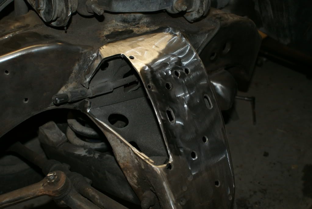
I'm picking up a used GTO A/C compressor, so I'll be able to choose between that and the F-body compressor to see which one works the best. A fellow swapper here on the forum measured his GTO compressor for me, and it looks like from front to back, it's the same length as the F-body compressor. The key difference appears to be the side exit versus rear exit A/C lines. I cut the notch deep enough that I'll have enough room for either compressor / line setup.
I'm picking up a used GTO A/C compressor, so I'll be able to choose between that and the F-body compressor to see which one works the best. A fellow swapper here on the forum measured his GTO compressor for me, and it looks like from front to back, it's the same length as the F-body compressor. The key difference appears to be the side exit versus rear exit A/C lines. I cut the notch deep enough that I'll have enough room for either compressor / line setup.
03-27-2009, 09:21 PM
#77

kst8...in post #52 you were inquiring about other ways to rig the engine/trans other that 2x chains at the rear of the block.
My friend came up with angle iron bridge that picks up the M10 tapped holes above the exhaust manifold flange on the rh and lh cylinder head. In this manner, the eng/trans is rigged w/ 2 chains in front and a third point the "eye" bolt over the top of the bridge.
We were able to install the eng/trans package with intake manifold installed and at the same time clear the ac housing of the 85 Monte. Did have to pull driver side valve cover for the installation, plenty of room to re-install once engine in posn. Required no chains to rear of engine....
03-27-2009, 09:35 PM
#78
On The Tree
Thread Starter
iTrader: (6)
Join Date: Mar 2006
Location: Kansas
Posts: 192
Likes: 0
Received 0 Likes
on
0 Posts
The new holes aren't straight back from the old ones. I just bolted the motor mounts and frame stands to the engine during my trial fit and moved the engine and tranny around until everything was in the right position (correct angles and best clearances). Once I was satisfied with the position, I used a permanent marker to mark the location of the frame stands on the crossmember. I pulled the engine/tranny back out, drilled the new holes, and bolted the frame stands into their new positions.
My final mounting position has the engine/tranny offset toward the passenger side approximately 3/8" for best clearances.
03-30-2009, 09:12 PM
#80
On The Tree
Thread Starter
iTrader: (6)
Join Date: Mar 2006
Location: Kansas
Posts: 192
Likes: 0
Received 0 Likes
on
0 Posts
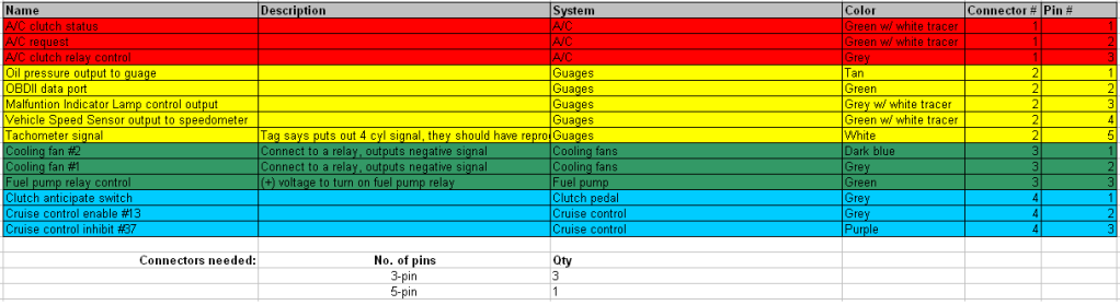
To get the wiring process started, I made a list of the wires I'll need to connect from the Wait4Me-modified harness. After that, I decided which wires to group together into multi-pin connectors. The table below is what I ended up with.
The plan is to use 4 connectors (3 3-pin and 1 5-pin). My initial thought is to use weatherpack connectors, but since all of this will be located under the dash, weatherpacks are probably overkill. Any suggestions on alternative connectors to weatherpacks? If I can buy something locally, that's better yet.
In addition to finding / buying the connectors, my next task is to find my Chevelle wiring schematic (I know I've got one somewhere, but it's hiding from me...) and identify which underdash wire I'll need to connect the tach signal to. For the water temperature guage, should I install the Chevelle's existing sending unit into the LS1?