
ECU Pinout questions
 04-14-2010, 09:27 AM
#1
Staging Lane
Thread Starter
iTrader: (5)

Join Date: Jul 2008
Location: South Carolina
Posts: 80
Likes: 0
Received 0 Likes
on
0 Posts

I am scratch wiring my entire car and i'm almost done with the engine portion of the harness. Just have a few questions about a few pins.
2000 Camaro 5.7 6 speed harness is what i'm making.
BLUE CONNECTOR C1?
PIN:33 TCC/CRUISE BRAKE SW IN where do i put this one? do I need it? No cruise in the car.
PIN:34 PNP SW SIG Where does this go and do I need it?
Red Connector C2?
What does tcc stand for? Torque converter control? for auto?
PIN: 2 TCC PWM SOL VALVE CTRL? Do i need this? where does it go?
PIN: 6 pc sol valve hi? Do i need this where does it go?
PIN: 8 pc sol valve lo? do i need this where does it go?
PIN: 30 Theft deter. fuel enable. I dont have a theft box anymore so what should I do with this wire?
PIN: 42 tcc sol valve control do i need this where does it go?
PIN: 44 reverse inhibit.... I assume this prevents me from hitting reverse instead of 5th gear? goes to a connector on the trans?
Then I have more questions about the fuel wires coming into the car.
There's
brown / white tied together no clue where they go.
Red / black tied together same thing no idea.
black - ground
grey - fuel relay energized when on
purple - fuel level ?
Sorry for all the questions but hopefully someone can help. If we can figure out the rest of this I can fire her up friday night.
Thank You!
 04-14-2010, 01:37 PM
#2

C1 is blue, C2 is red, you are correct
B33 brake sw. This is a wierd one. You sort of need it but can get by without it. To unlock the reverse lock, the computer needs to see a speed of 0 and the brakes applied. Not using the brake switch wire you can attach it to a switch on your brake pedal thats N/O and grounds when depressed
B32 and B34 are PNP switch wires depending on the trans type. The PCM is supposed to look for a ground signal to enable fuel. I ground them both for manual cars and hook them to the shifter PNP switch for autos. Ive seen alot of cars successfully run without either wire grounded or even present, so they may be something in the tune you can uncheck
Most of your C2 questions are about the auto wires. Check this out and remove them all
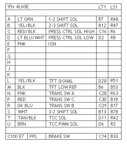
Here is trans wiring for M6 cars. You can leave out CAGS as well if you remove the feature in teh tune, otherwise itll throw a code

R30 is the signal wire from the VATS module telling the PCM that your key is A-ok and allows it to enable fuel. If VATS is tuned out, this wire goes away
Are you talking about the fuel pump sender connector or a relay?
B33 brake sw. This is a wierd one. You sort of need it but can get by without it. To unlock the reverse lock, the computer needs to see a speed of 0 and the brakes applied. Not using the brake switch wire you can attach it to a switch on your brake pedal thats N/O and grounds when depressed
B32 and B34 are PNP switch wires depending on the trans type. The PCM is supposed to look for a ground signal to enable fuel. I ground them both for manual cars and hook them to the shifter PNP switch for autos. Ive seen alot of cars successfully run without either wire grounded or even present, so they may be something in the tune you can uncheck
Most of your C2 questions are about the auto wires. Check this out and remove them all
Here is trans wiring for M6 cars. You can leave out CAGS as well if you remove the feature in teh tune, otherwise itll throw a code
R30 is the signal wire from the VATS module telling the PCM that your key is A-ok and allows it to enable fuel. If VATS is tuned out, this wire goes away
Are you talking about the fuel pump sender connector or a relay?
04-14-2010, 02:46 PM
#3
Staging Lane
Thread Starter
iTrader: (5)
Join Date: Jul 2008
Location: South Carolina
Posts: 80
Likes: 0
Received 0 Likes
on
0 Posts
That was a boatload of help I really really appreciate it.
All set with the Blue and Red connectors now. THANK YOU!
The fuel wires i am referring to are all of the wires that come into the car via the drivers rear seat. There's a small harness there I need to know what those wires are for.
I have 7 wires...
red and black which are spiraled together
brown and white which are spiraled together
a larger black wire
a grey wire which goes to the relay which i assume is hot since if I energize this i get fuel.
Purple
Thank you in advance!
 04-14-2010, 10:38 PM
#5
Staging Lane
Thread Starter
iTrader: (5)
Join Date: Jul 2008
Location: South Carolina
Posts: 80
Likes: 0
Received 0 Likes
on
0 Posts
That clears up everything except I have a couple of new ones that I forgot about cause I was at work....
Blue C1 Connector:
23: gray - fuel pressure / sender ground ... where's this go? or can I ignore it
46: Gray - Fuel tank pressure 5 v reference
Red C2 Connector:
54: Purple - fuel lever signal... Do I have to put the purple wire from the sender into the ecu or can I just put it straight to a gauge?
64: Dark Green - Fuel tank pressure signal. what do I do with this one?
04-15-2010, 08:21 AM
#6
Fuel pressure stuff goes to the sensor on the tank. You need this stuff to keep EVAP function. If you're not using EVAP or the LS1 plastic fuel tank delete these wires
Fuel level wire doesnt do much for a swap car without the LS1 Fbody cluster. Wire your fuel sender directly to the gauge, but be aware the LS1 Fbodys used a different resistance range on their senders. A universal 90OHM sender can be retrofitted to the pump assembly rather easily and run 90% of the guages out there
Fuel level wire doesnt do much for a swap car without the LS1 Fbody cluster. Wire your fuel sender directly to the gauge, but be aware the LS1 Fbodys used a different resistance range on their senders. A universal 90OHM sender can be retrofitted to the pump assembly rather easily and run 90% of the guages out there
04-15-2010, 10:55 AM
#7
Staging Lane
Thread Starter
iTrader: (5)
Join Date: Jul 2008
Location: South Carolina
Posts: 80
Likes: 0
Received 0 Likes
on
0 Posts
I'm actually using the 1994 camaro stock fuel tank and sender with no EVAP however put a 255 ml/hr pump in there for the time being. Maybe this wire will work for my fuel level then with my aftermarket gauge setup.
I will delete all of those wires then... I still don't know why I try too hard to do things ... I always make it more difficult on myself lol.
Thank you for the information needed to start my car up tomorrow.
I will delete all of those wires then... I still don't know why I try too hard to do things ... I always make it more difficult on myself lol.
Thank you for the information needed to start my car up tomorrow.
Trending Topics
04-17-2010, 07:29 AM
#10
Staging Lane
Thread Starter
iTrader: (5)
Join Date: Jul 2008
Location: South Carolina
Posts: 80
Likes: 0
Received 0 Likes
on
0 Posts
Alright. I fired up the car last night. However the oxygen sensors aren't functioning properly.
The sensors are out of a 2000 silverado 2500 with a 6.0. The wires are black, light blue, brown and black/white. Can someone please inform me as to which wires are which? I know that one is ground one is ignition hot one is h20s hi and one is lo.
Thank You
The sensors are out of a 2000 silverado 2500 with a 6.0. The wires are black, light blue, brown and black/white. Can someone please inform me as to which wires are which? I know that one is ground one is ignition hot one is h20s hi and one is lo.
Thank You
04-17-2010, 08:32 AM
#12
Staging Lane
Thread Starter
iTrader: (5)
Join Date: Jul 2008
Location: South Carolina
Posts: 80
Likes: 0
Received 0 Likes
on
0 Posts
This 4 wire harness I removed from the frame rail of a 2000 2500 6.0 chevy truck. My yard guy... I work @ a junkyard cut the wires off of an O2 sensor in the yard and gave me the same thing. I've been looking everywhere for these colors to match them up.
Or if you could tell me what the wires go to from left to right on the sensor... or how to figure out what is what.
I searched online for 2.5 hours last night and another .5 hours today with no luck. I'm rather frazzled.
The sensor itself has a tan, 2 browns and I forget the other color
Or if you could tell me what the wires go to from left to right on the sensor... or how to figure out what is what.
I searched online for 2.5 hours last night and another .5 hours today with no luck. I'm rather frazzled.
The sensor itself has a tan, 2 browns and I forget the other color
04-17-2010, 08:37 PM
#14
A Tan or Tan/Wht Low signal
B Ppl or Ppl/wht Hi signal
C Blk grd
D Pnk ign
Oddly enough, the letter assignment is the same for both the flat and male/female square O2 connectors. Im looking at all 3 types right now
http://www.lt1swap.com/pictures/10_o2_sensors.gif
B Ppl or Ppl/wht Hi signal
C Blk grd
D Pnk ign
Oddly enough, the letter assignment is the same for both the flat and male/female square O2 connectors. Im looking at all 3 types right now
http://www.lt1swap.com/pictures/10_o2_sensors.gif
04-17-2010, 10:14 PM
#15
Staging Lane
Thread Starter
iTrader: (5)
Join Date: Jul 2008
Location: South Carolina
Posts: 80
Likes: 0
Received 0 Likes
on
0 Posts
The true problem is that I don't know where each wire goes to each oxygen sensor... When I plug the male end of the plug into the female end I am left with 4 bare wires. Black, Black / White, light blue and brown. I dont know which wire is heat or ground etc... I wish I had a picture of someone's connector then i'd know which wire is which.
04-18-2010, 11:01 AM
#17
Staging Lane
Thread Starter
iTrader: (5)
Join Date: Jul 2008
Location: South Carolina
Posts: 80
Likes: 0
Received 0 Likes
on
0 Posts
I should have noticed that you put A B C D next to the colors. Sorry about that... I have it under control now. When I am at my car on Monday I'll wire it up and see if the fuse stays this time.
Thanks again pocket you've been a great help.
Thanks again pocket you've been a great help.