
A couple quick wiring questions!
 05-02-2010, 04:59 PM
#1
On The Tree
Thread Starter
iTrader: (5)

Join Date: May 2008
Location: Moorhead Minnesota
Posts: 177
Likes: 0
Received 0 Likes
on
0 Posts

I have a few questions to finish up my wiring diagram.
1. The Temp sensor has two wires, but the PCM pinout I'm using (LT1swap) only shows one wire, going to C1-74. Is the other wire just a ground? Same deal for the VSS and CEL. (I assume CEL just needs a ground)
2. How exactly does the factory combine multiple wires? I have half the injectors and half the coils running to one fuse. (As my Current Performance fuse block says) What is the best, cleanest way to combine eight wires down to one? I can't find anything on it searching the net, plus my wiring book is worthless. (HP's Automotive Electrical Handbook)
3. Does anybody have a source for the GM connectors and wiring? I was going to use EFIConnection (Still going to try them) but their Web site says they aren't taking orders on wiring until later. I would also like the metal connectors themselves (That go into the connector, crimped onto the wire) if anybody knows where I can get those. If it's possible I would like to have my harness without any splices, but we'll see. I suppose I will need the tool also.
4. What gauge wire exactly is the factory stuff? Using my wire stripper it seems like it's either 20 or 22 gauge. I'll probably just go with the heavier stuff.
Thank you so much for reading, any responses would be great!
 05-02-2010, 08:50 PM
#2
TECH Resident
iTrader: (55)
Join Date: Oct 2005
Location: Cleveland, Oh
Posts: 847
Likes: 0
Received 0 Likes
on
0 Posts
The connectors can also be found on ebay.
The factory uses slpice connections. basically a bunch of wire ends soldored together. You can do that or center slice them along a main wire (cut an inch of covering off of a wire, wrap a wire end around the exposed wire and solder.
The factory uses slpice connections. basically a bunch of wire ends soldored together. You can do that or center slice them along a main wire (cut an inch of covering off of a wire, wrap a wire end around the exposed wire and solder.
05-02-2010, 09:24 PM
#3

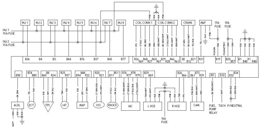
1) Pin locations change per PCM. 99-02 Fbody is B74 Yel signal and B80 Blk low ref
2) GM uses a common splice wrapped with a sealant lined shrink tube. They are black with white print and easy to ID. The easiest way to join them is like Rick posted
3) EFI connection is a great place. #2 is ebay. #3 is good for cheap common connectors needed in a hurry, JY. LSx connectors are common on econo FWD cars of the early 90s
4) 18-20ga depending on purpose. Coils, INJ, and fuse wires are all 18ga. Most sensors are 20ga. Grounds and powers are generally 18ga. Oddballs are relay related. Usually the donor harness has more than enough wire for those so you dont have to buy any
For future reference, I wouldnt use your strippers to measure wire size. Depending on the brand, they usually get it wrong. My strippers uses the 16ga hole for 20ga wire and 14ga hole for 16-18ga wire. 10-12ga cables wont even fit in the stripper without cutting some strands
05-02-2010, 10:43 PM
#4
I used to get leary about putting so many circuits onto the small guage Current Performance wire also. But, when you think about it from an electrical standpoint, it all makes perfect sense.
You are only firing one coil or one injector at a time. Therefore, the guage can be small as at any given time it's only firing one component, not all that are wired to that single wire.
As far as splicing, I do exactly as stated above, strip a 4" or so section, solder all connections to that wire and then heatshrink over it all.
05-03-2010, 12:19 AM
#6
On The Tree
Thread Starter
iTrader: (5)
Join Date: May 2008
Location: Moorhead Minnesota
Posts: 177
Likes: 0
Received 0 Likes
on
0 Posts
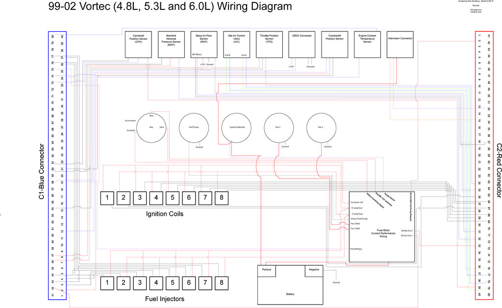
Here is my finished wiring diagram, for anybody interested. I don't think Flickr will let me post it too large. (Yup, I have a lot of time on my hands)
05-03-2010, 12:54 AM
#7
On The Tree
Thread Starter
iTrader: (5)
Join Date: May 2008
Location: Moorhead Minnesota
Posts: 177
Likes: 0
Received 0 Likes
on
0 Posts
Here it is in .PDF format. If anybody is interested in it give it a look over. I don't suggest wiring your swap based off it yet though, I still gotta wire mine up and make sure everything is right! It's large, I plan on having it printed before I start my wiring.
The wiring color is my own, as I tried to keep it down to a minimum for when I actually buy the wire. Got it down to about 10.
I have to figure out which pin on each connector is the right one too... should be fun. I love the punishment I guess.
The wiring color is my own, as I tried to keep it down to a minimum for when I actually buy the wire. Got it down to about 10.
I have to figure out which pin on each connector is the right one too... should be fun.
I love the punishment I guess. Trending Topics
 05-03-2010, 09:18 AM
#9
This is a great thread for helping me too. I just received my Current Performance fuse/relay box last week, and I am getting ready to join it to my modified harness. It will all get tucked under the dash in my '69 Nova. I was curious about splicing the injector wires together into one circuit on the fuse box, so I appreciate the answers above.
Pocket - your diagram really simplifies the whole process down. I appreciate the effort.
bmx - I'll print out your diagram and spend some time comparing it to my setup.
Pocket - your diagram really simplifies the whole process down. I appreciate the effort.
bmx - I'll print out your diagram and spend some time comparing it to my setup.
05-05-2010, 11:22 PM
#11
Launching!
iTrader: (1)

Join Date: Oct 2008
Location: Russellville, Arkansas
Posts: 215
Likes: 0
Received 0 Likes
on
0 Posts
What program did you use to make that diagram? That is really easy to understand. I would like to do that for my swap that will be a little different due to DBW, 2003 LM7.
05-06-2010, 05:27 AM
#12
On The Tree
Thread Starter
iTrader: (5)
Join Date: May 2008
Location: Moorhead Minnesota
Posts: 177
Likes: 0
Received 0 Likes
on
0 Posts
I used Illustrator CS3 for mine, but you could do it with paint as well. Illustrator is just nice because I put everything on its own layer so I can quickly change things if needed.