
general electric fan questions
 11-09-2010, 05:55 PM
#1
Launching!
Thread Starter


Hello,
Doing a swap into a 65 impala.
Basically, I am putting a stock radiator and set of fans in.
As for my questions, should I run two wires from the battery directly to each relay or is it better to run one wire then branch it off to the two relays?
If anyone is familiar with the older GM's, the voltage regulator is on the front near the headlights. I do not need this now that I am using a stock alternator with the voltage regulator inside of it.
I see the relays shown at http://www.lt1swap.com/fuseblock_obd2port.html are rated for 30 amp, so do I need a fuse or is that enough?
I plan on wiring to two relays since I am using the stock fans setup. The ECM should have two wires that I can run to the relay.
I have two grounding straps from the frame to the radiator support. Both go from the engine to the frame to the radiator support. I could I guess theoretically ground the fans from the support, but am unsure if this is a proper thing.

any suggestions appreciated.
Doing a swap into a 65 impala.
Basically, I am putting a stock radiator and set of fans in.
As for my questions, should I run two wires from the battery directly to each relay or is it better to run one wire then branch it off to the two relays?
If anyone is familiar with the older GM's, the voltage regulator is on the front near the headlights. I do not need this now that I am using a stock alternator with the voltage regulator inside of it.
I see the relays shown at http://www.lt1swap.com/fuseblock_obd2port.html are rated for 30 amp, so do I need a fuse or is that enough?
I plan on wiring to two relays since I am using the stock fans setup. The ECM should have two wires that I can run to the relay.
I have two grounding straps from the frame to the radiator support. Both go from the engine to the frame to the radiator support. I could I guess theoretically ground the fans from the support, but am unsure if this is a proper thing.
any suggestions appreciated.
 11-09-2010, 06:35 PM
#2

If you want the fans to operate just like they would in a stock f-body then you need three relays. If you just want the fans to be able to come on at seperate temps, one fan at each different temp, then two relays will work. The signal put out by the pcm is a ground signal so wire you relays with that in mind. You will run a wire from the battery to the relays and out to the fans, but the relay power will still need to be switched 12V.
11-25-2010, 03:22 AM
#3
Launching!
Thread Starter
is there a chance that someone could take a photo of their setup for me?
I am wondering how they branched the power and ground wires off of a battery cable. I also wondered how they ran the positive to the relay.
Thanks for any help.
I am wondering how they branched the power and ground wires off of a battery cable. I also wondered how they ran the positive to the relay.
Thanks for any help.
11-25-2010, 09:09 AM
#5
Launching!
Thread Starter
the ends of the wire are jammed in the radiator support to show them in the photo.
They will have wire loom on them from the bottom of the fan eyelets.
Thanks for the concern.
They will have wire loom on them from the bottom of the fan eyelets.
Thanks for the concern.
11-25-2010, 09:27 AM
#6
1. You can ground the fans to the support, that will work fine.
2. Put some RTV over that ground to prevent corrosion..
3. If you're really going to run those wires through that hole in the core support, and you like your car to be like it is right now, instead of extra crispy, put a grommet in there, please.
4. One 8 or 10- gauge wire to the relays from the battery or buss bar is fine. I ran mine in series.
5. Whoever said you need 3 relays, is wrong. You only need two.
Run your 8-10 gauge wire to both fans (+) directly. You can do a nice solder splice, shrink wrap it, before the fan split.. Put your 30A inline fuse between each leg and the fan.
Mount your two relays on the core support.
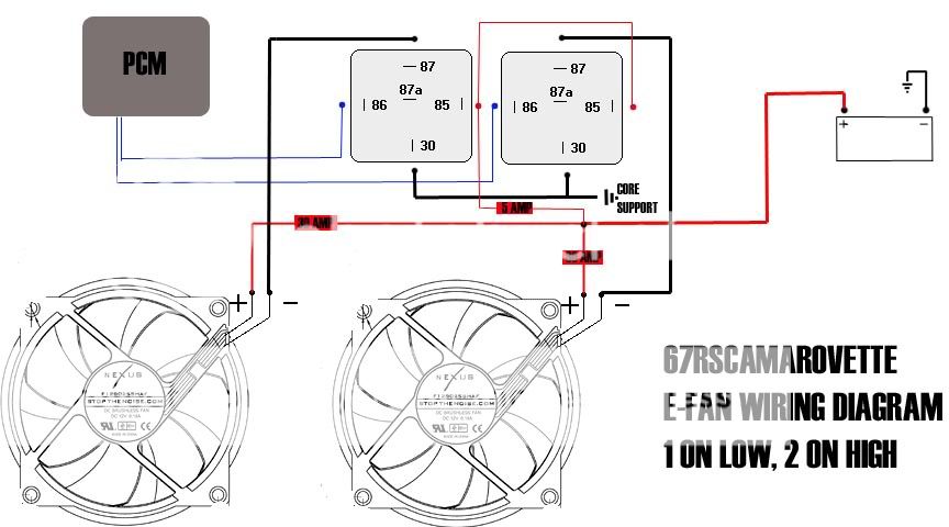
Pin 86 will be the wires from your PCM.. (1 to each relay)
Pin 30 will go directly to a good ground (both relays together)
Pin 87 will go directly to the ground wire of each fan (1 to each relay)
Pin 85 will go to any 12v source (5a fuse is more than enough for both)
The PCM sends a ground when it wants a fan turned on. Since the positive side of the circuit is always "hot" with this setup, all it does is turn "on" the fans by completing the ground circuit. This way will set up 1 fan to come on at "low" speed, and both to come on at "high" speed. Good luck.
2. Put some RTV over that ground to prevent corrosion..
3. If you're really going to run those wires through that hole in the core support, and you like your car to be like it is right now, instead of extra crispy, put a grommet in there, please.
4. One 8 or 10- gauge wire to the relays from the battery or buss bar is fine. I ran mine in series.
5. Whoever said you need 3 relays, is wrong. You only need two.
Run your 8-10 gauge wire to both fans (+) directly. You can do a nice solder splice, shrink wrap it, before the fan split.. Put your 30A inline fuse between each leg and the fan.
Mount your two relays on the core support.
Pin 86 will be the wires from your PCM.. (1 to each relay)
Pin 30 will go directly to a good ground (both relays together)
Pin 87 will go directly to the ground wire of each fan (1 to each relay)
Pin 85 will go to any 12v source (5a fuse is more than enough for both)
The PCM sends a ground when it wants a fan turned on. Since the positive side of the circuit is always "hot" with this setup, all it does is turn "on" the fans by completing the ground circuit. This way will set up 1 fan to come on at "low" speed, and both to come on at "high" speed. Good luck.
Trending Topics
11-30-2010, 06:15 PM
#8
Launching!
Thread Starter
Thanks for the diagram. You help is greatly appreciated.
I did not check after your first post.
You mentioned using RTV on the ground wires. I am guessing just regular? Blue, black, clear? Just brush it on or coat the wire thoroughly?
I see a branch of wire with a 5 amp fuse. Is this what you would wire to the pcm?
This is what I did. Let me know if you think it is OK. I wired the fans with 12 gauge wire. I saw some posts that said 14 was not thick enough and would melt over time.
I do have a couple more questions though.
Basically I solder the battery cable (4 gauge wire) to the 12 gauge I am using to go to the fuse then relay? Am I correct that most fuses use 14 gauge wire? They say rated for 30A, but are 14 gauge.
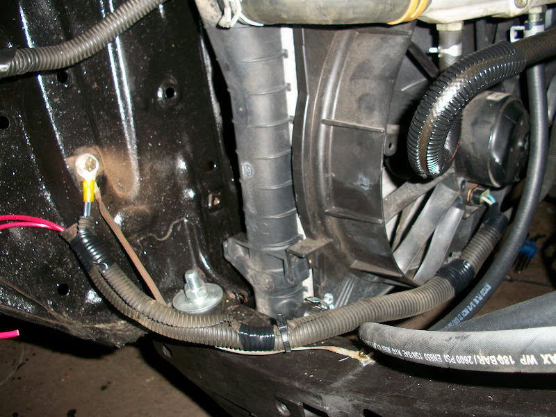
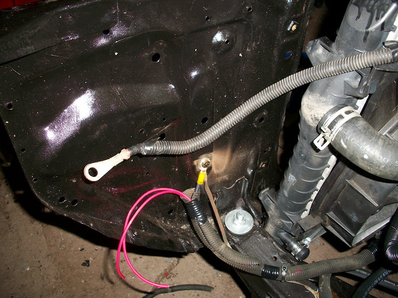
photo of relay I am using.
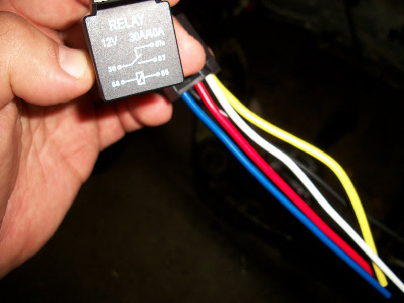
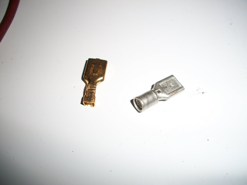
photo of relay plug with 14 gauge wire, I made new ends on the wire and did not use the plug wires.

I could not get the correct terminal to work (the one with the tab to stop pulling out) so I used the right size one for the gauge wire. the problem was that the 12 gauge wire would not fit inside the crimp part.
crimped end
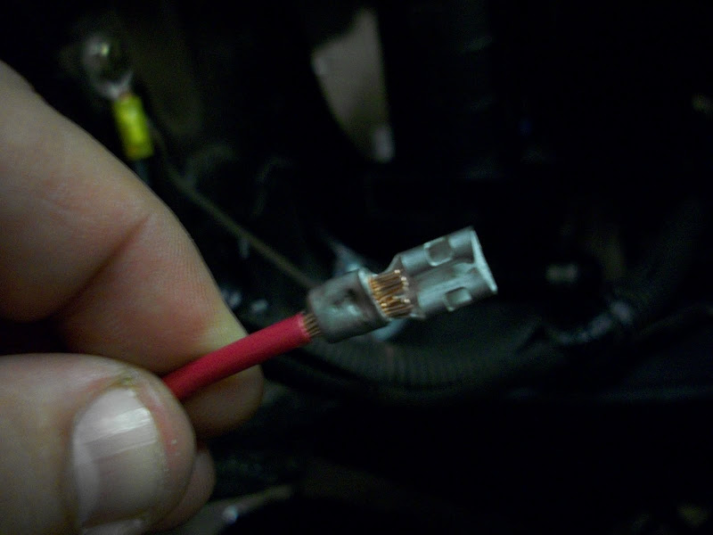
shrink wrap over the crimp
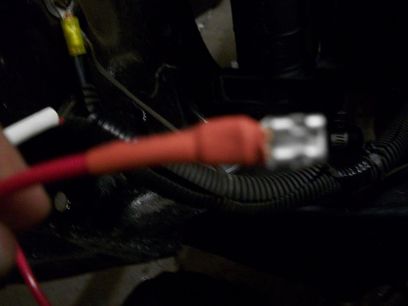
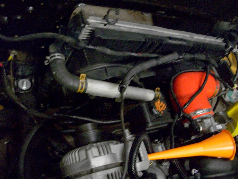
wiring on top of engine. I plan on putting one more cable retainer on the fan shroud.
I did not check after your first post.
You mentioned using RTV on the ground wires. I am guessing just regular? Blue, black, clear? Just brush it on or coat the wire thoroughly?
I see a branch of wire with a 5 amp fuse. Is this what you would wire to the pcm?
This is what I did. Let me know if you think it is OK. I wired the fans with 12 gauge wire. I saw some posts that said 14 was not thick enough and would melt over time.
I do have a couple more questions though.
Basically I solder the battery cable (4 gauge wire) to the 12 gauge I am using to go to the fuse then relay? Am I correct that most fuses use 14 gauge wire? They say rated for 30A, but are 14 gauge.
photo of relay I am using.
photo of relay plug with 14 gauge wire, I made new ends on the wire and did not use the plug wires.
I could not get the correct terminal to work (the one with the tab to stop pulling out) so I used the right size one for the gauge wire. the problem was that the 12 gauge wire would not fit inside the crimp part.
crimped end
shrink wrap over the crimp
wiring on top of engine. I plan on putting one more cable retainer on the fan shroud.
12-02-2010, 07:21 AM
#10

As for my questions, should I run two wires from the battery directly to each relay or is it better to run one wire then branch it off to the two relays?
Here, I drew you a picture. Makes it a lil easier.
12-02-2010, 07:26 AM
#11
Launching!
Thread Starter
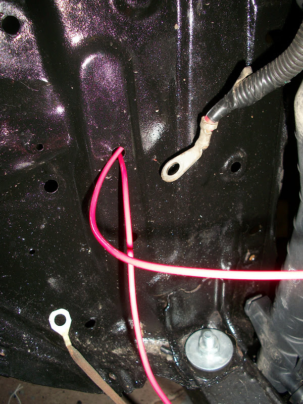
Look again please. Photo #1 shows the grounding side of the fans. I have the ground wires for the fan sent to the radiator support with a grounding strap from the frame. I also grounded the support on the other side of the radiator (passenger side) to be safe.
I am trying to find a terminal block that I am happy with. I dont want to have any part of the hot posts exposed.
I am trying to find a terminal block that I am happy with. I dont want to have any part of the hot posts exposed.
12-02-2010, 09:52 AM
#12
The best way is to run the ground wire all the way back to the battery.
Your life will be a lot happer if you never rely on chassis grounds to carry current. They can cause all sorts of problems that can take years to show up.
Also the current capacity of a wire is dependent not only upon the wire gauge but the length of the circuit.
Your life will be a lot happer if you never rely on chassis grounds to carry current. They can cause all sorts of problems that can take years to show up.
Also the current capacity of a wire is dependent not only upon the wire gauge but the length of the circuit.
12-03-2010, 08:41 AM
#13
The best way is to run the ground wire all the way back to the battery.
Your life will be a lot happer if you never rely on chassis grounds to carry current. They can cause all sorts of problems that can take years to show up.
Also the current capacity of a wire is dependent not only upon the wire gauge but the length of the circuit.
Your life will be a lot happer if you never rely on chassis grounds to carry current. They can cause all sorts of problems that can take years to show up.
Also the current capacity of a wire is dependent not only upon the wire gauge but the length of the circuit.
Last edited by 67RSCamaroVette; 12-03-2010 at 08:49 AM.
12-03-2010, 08:44 AM
#14
Your setup looks adequate.. the 30A bosch style relay you have, is what you need. I like to solder all of those spade connections, as they loosen/corrode over time.. You've got a good crimp and heat-shrink, that will be a reliable connection. When I wire vehicles, and i'm forced to use a spade terminal, I get a propane blow-torch, heat the spade part for a few seconds (not so much that it burns the insulation of the wire) and dab solder at the exposed copper until it's no longer visible. It'll make the connection last a very long time.
Looking at your ground setup... why not just run the ground to the frame, where your ground strap is coming from?
Looking at your ground setup... why not just run the ground to the frame, where your ground strap is coming from?
Last edited by 67RSCamaroVette; 12-03-2010 at 08:51 AM.