
WTF? Alternator issue. Shouldn't a resistor reduce the voltage?
 04-10-2011, 04:14 PM
#1

Hey guys,
BACKGROUND: This is a carb swap so no PCM alternator wiring involved. I'm using a factory 99 F-body alternator. I wired it with a stock plug that has a single wire going to terminal "L". I wired this to a 12v switched source with a 470ohm 1/2 watt resistor inline as I've read on a at least a hundred times. I went on blind faith and didn't measure the voltage at the plug. The alternator was charging fine (between 13.9-14.2v) until yesterday.
ISSUE: Yesterday the alternator stopped charging. I assumed that there was an issue somewhere in the "exciter wire" circuit, so I tested the voltage at the plug. It measured like 12.2v. So I was like WTF? I thought that 470ohm 1/2 watt resistor was supposed decrease the voltage of this wire to like 8.X volts? I assumed something was wrong that was giving this plug full voltage so I disected my wiring job to look for the issue. When I found nothing visibly wrong, I cut out the resistor and replaced it with another. But I still get the same thing. I measure 12.X volts on both sides of the resistor, and all the way out to the plug end. I also have some other resistors laying around (220 ohm 1/2 watt and 2.2K ohm 1/2 watt). So I tested for voltage drop with those ones as well and they don't reduce the volatage a single bit either.
So, am I completely misunderstaning how this works? I thought a resistor introduced resistence into a circuit to reduce the voltage? If my alterator was seeing a full 12v to this wire, I'm sure I fried it. I guess I can accept that, but how do I keep it from happening again if these resistors aren't reducing the voltage on my volt meter? I'm stumped guys. I'm sure there's something here I'm missing. Please help.
 04-10-2011, 05:38 PM
#2

A good charging system should see 14.4v during run and 12.0v when off
This is your problem. You either installed the wrong resistor or soldered it in improperly. You need a yellow, violet, brown, gold/silver resistor. To install it you must cut the wire and solder the resistor in between the ends so all the voltage goes completely through the resistor. Simply stripping back a length of wire and soldering it on isnt enough
I measure 12.X volts on both sides of the resistor,
04-10-2011, 06:17 PM
#3
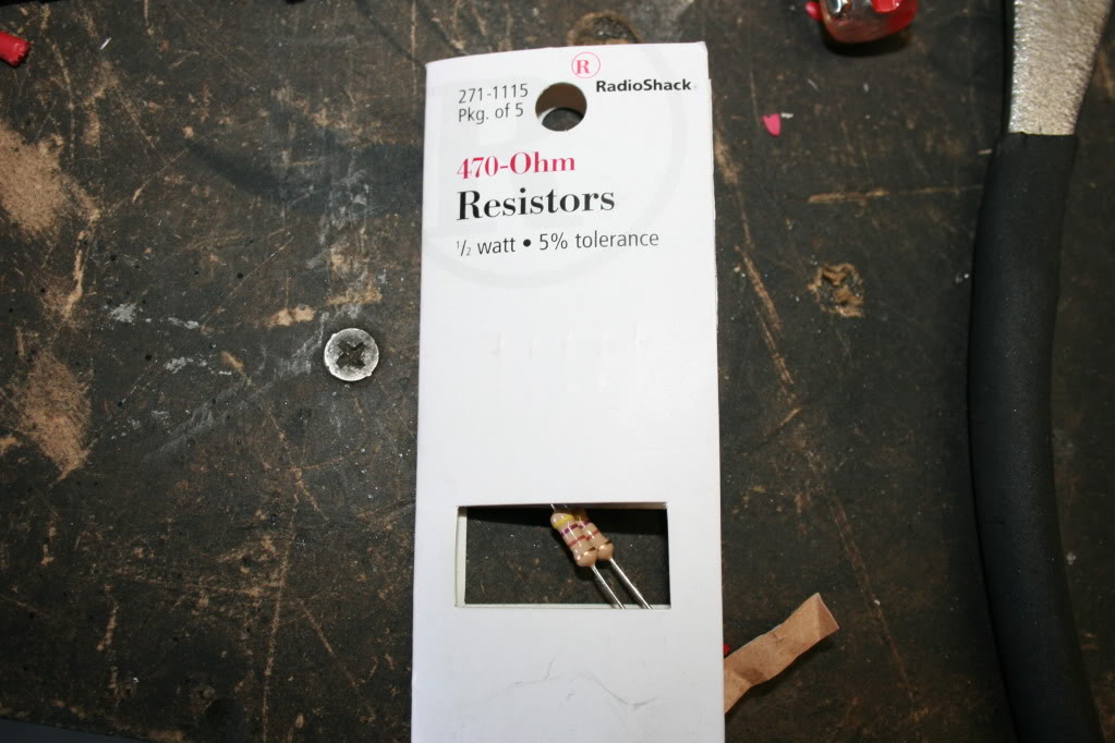
Ok, maybe this will help some. This is the resistor I am using.
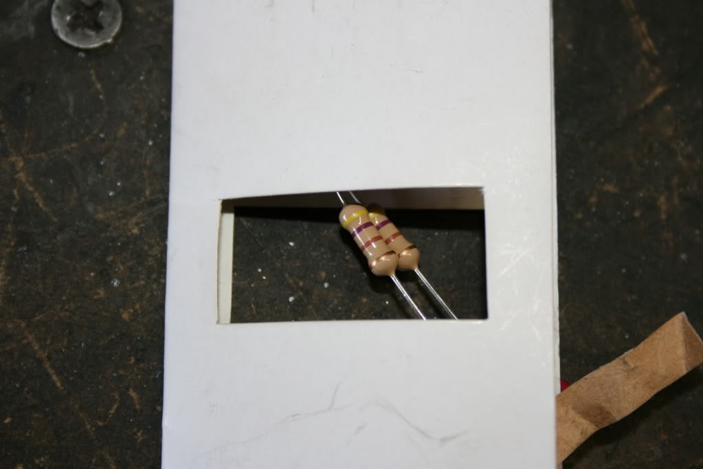
Close up shows a yellow, violet, brown (orangish), gold pattern.
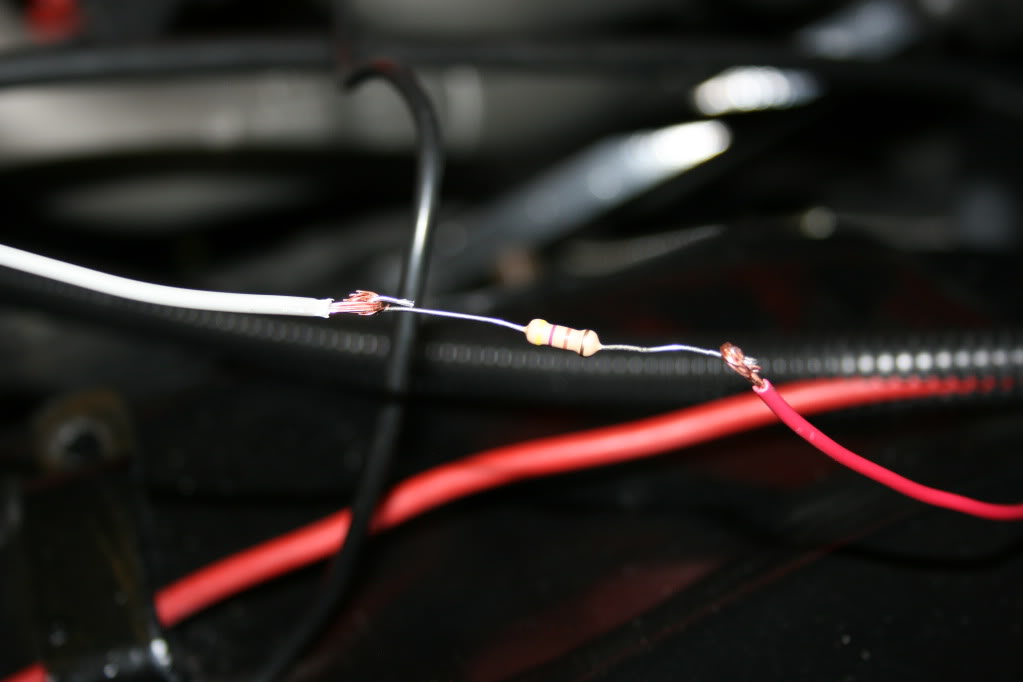
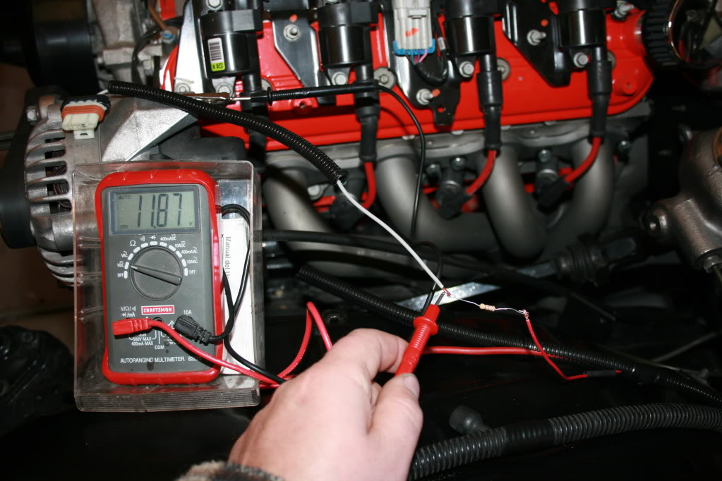
Here is how it is being installed. The red wire to the right is the switched 12v source. The gray wire on the left is going to the alternator plug. I am soldering the resistor between these two wires so that the two wires are connected only by the resistor. This is just mocked up for clarity and is not yet soldered. After soldering, it is covered by shrink tube.
With the car off and the key in the run position and the plug disconnected from the alternator, I measure 11.87v on the pre-resistor side, just as I would expect….battery voltage. Yes, the voltage is a little low now because of running the motor with the alternator not charging.
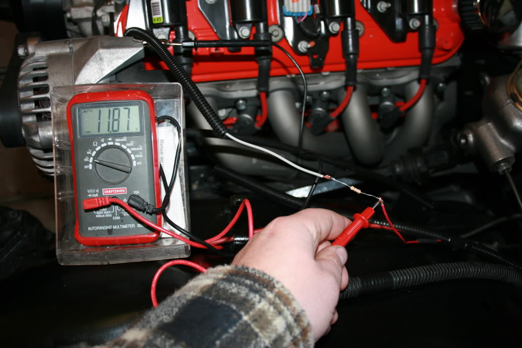
Now, with the same conditions as above, I measure the voltage after the resistor, and still get the same voltage as before; 11.87v. This is the same, even if I measure it at the plug, which really shouldn’t make a difference since it’s all after the resistor. This is what has me confused. Shouldn’t this be a reduced voltage after the resistor?
While taking these shots, it occurred to me to test it with the plug plugged in to the alternator. When I did that, I got a drastic reduction to 1.244 volts after the resistor and the “pre-resistor” side stayed at 11.87v.
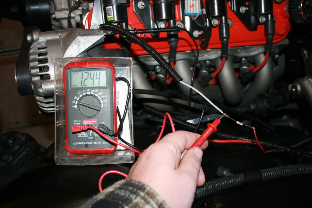
So, maybe this answers my question about the voltage reduction (I guess it had to be plugged in to show the resistence added?), but this now seems like a TON of voltage reduction and I’m still not sure why my alternator **** the bed. It is the original off my 99 TA, so maybe it just died a natural death, but I want to be sure before I buy a new one and burn it up as well.
Close up shows a yellow, violet, brown (orangish), gold pattern.
Here is how it is being installed. The red wire to the right is the switched 12v source. The gray wire on the left is going to the alternator plug. I am soldering the resistor between these two wires so that the two wires are connected only by the resistor. This is just mocked up for clarity and is not yet soldered. After soldering, it is covered by shrink tube.
With the car off and the key in the run position and the plug disconnected from the alternator, I measure 11.87v on the pre-resistor side, just as I would expect….battery voltage. Yes, the voltage is a little low now because of running the motor with the alternator not charging.
Now, with the same conditions as above, I measure the voltage after the resistor, and still get the same voltage as before; 11.87v. This is the same, even if I measure it at the plug, which really shouldn’t make a difference since it’s all after the resistor. This is what has me confused. Shouldn’t this be a reduced voltage after the resistor?
While taking these shots, it occurred to me to test it with the plug plugged in to the alternator. When I did that, I got a drastic reduction to 1.244 volts after the resistor and the “pre-resistor” side stayed at 11.87v.
So, maybe this answers my question about the voltage reduction (I guess it had to be plugged in to show the resistence added?), but this now seems like a TON of voltage reduction and I’m still not sure why my alternator **** the bed. It is the original off my 99 TA, so maybe it just died a natural death, but I want to be sure before I buy a new one and burn it up as well.
Last edited by GC99TA; 04-10-2011 at 06:25 PM.
04-10-2011, 07:55 PM
#4
Well, I GUESS my issue is solved for now. I took the alternator off and had it tested at Autozone. It failed immediately and the machine never even spun the thing. I wasn't sure if the guy had done everything correct, so I asked him to test a remanufactured one they had in stock. It tested fine and the machine spun it, so I'm guessing my old one was in fact junk. I watched him hook both of them up and he did it the same way both times.
So I bought the remanufactured one he tested and brought it home, installed it and, repeated my voltage tests before and after the resistor....both with the plug plugged in and without. Everything was the same except this time I got a reading of .746v after the resistor with the plug plugged in. So, I fired the car up and the charge slowly started to climb until it finally reached just under 14.4v at the alternator lug with my voltmeter and 14.1 on my cigarette lighter plug in gauge.
So hopefully the last one had just died a "natural" death and it wasn't caused by my wiring. But (undertanding that I'm not electrically smart) I guess I still don't understand why the thing needs to be plugged in before I get a reduced voltage reading after the resistor. So, if anyone can shed some light on that to make me feel better, that would be great. Either way though, at least I now have a "disposable" alternator with a lifetime warranty so if I burn this one up it'll go back to the store until I figure out what I'm doing wrong.
04-10-2011, 08:44 PM
#6
Thanks. Like I said above, that was just a temp job for testing/photo purposes. I have since soldered the connections and covered the whole deal with shrink tube.
Yeah, I'm hoping the alt just failed on it's own like suggested. Yeah, I've heard the horror stories of reman alts. I guess I just picked this one up today because this whole issue would have driven me crazy until I got some resolution. Hopefully it at least lasts long enough for me to feel comfortable with my wiring.
Yeah, I'm hoping the alt just failed on it's own like suggested. Yeah, I've heard the horror stories of reman alts. I guess I just picked this one up today because this whole issue would have driven me crazy until I got some resolution. Hopefully it at least lasts long enough for me to feel comfortable with my wiring.
04-10-2011, 11:51 PM
#7
You are not going to see a voltage drop with a digital meter, as any decent digital meter is a high impedance model (It takes almost no amperage to drive the meter)
Since
voltage = Amperage / Resistance
Because you have very little current draw from the meter, there will be very little change in voltage. Now if you had a large current draw going across the resistor there would also be a large current drop.
Since
voltage = Amperage / Resistance
Because you have very little current draw from the meter, there will be very little change in voltage. Now if you had a large current draw going across the resistor there would also be a large current drop.
Trending Topics
04-11-2011, 07:42 AM
#8
You are not going to see a voltage drop with a digital meter, as any decent digital meter is a high impedance model (It takes almost no amperage to drive the meter)
Since
voltage = Amperage / Resistance
Because you have very little current draw from the meter, there will be very little change in voltage. Now if you had a large current draw going across the resistor there would also be a large current drop.
Since
voltage = Amperage / Resistance
Because you have very little current draw from the meter, there will be very little change in voltage. Now if you had a large current draw going across the resistor there would also be a large current drop.
04-11-2011, 12:53 PM
#9
This is a great observation that you don't hear enough about. Nobody tells you this when you buy a digital meter.
Also, if it will help you sleep better at night, check out the link in this post:
https://ls1tech.com/forums/14588749-post87.html
It is the service manual for the CS-130 family of alternators, which is electrically the same as the CS-130D that you have from your Camaro. The last couple pages of the manual tell you about bench testing, and the recommended resistor options for running the alternator. I know there has been a lot of discussion about the Camaro alternator, but it's nice to get information straight from the manufacturer.
Also, does your alternator light actually come on with the 470 ohm resistor wired inline with the light? Mine will barely glow with a 22 ohm resistor. To fix this, the next time I am in there, I am going to put in another wire that goes straight to an ignition switched +12v supply, put a resistor in that wire, and then take out the resistor that goes to the alternator light. That way, the alternator will still incur resistance, and my light will shine bright. (Basically I will be wiring another circuit in parallel, which will be used to increase the resistance to the alternator.)
You are not going to see a voltage drop with a digital meter, as any decent digital meter is a high impedance model (It takes almost no amperage to drive the meter)
Since
voltage = Amperage / Resistance
Because you have very little current draw from the meter, there will be very little change in voltage. Now if you had a large current draw going across the resistor there would also be a large current drop.
Since
voltage = Amperage / Resistance
Because you have very little current draw from the meter, there will be very little change in voltage. Now if you had a large current draw going across the resistor there would also be a large current drop.
https://ls1tech.com/forums/14588749-post87.html
It is the service manual for the CS-130 family of alternators, which is electrically the same as the CS-130D that you have from your Camaro. The last couple pages of the manual tell you about bench testing, and the recommended resistor options for running the alternator. I know there has been a lot of discussion about the Camaro alternator, but it's nice to get information straight from the manufacturer.
Also, does your alternator light actually come on with the 470 ohm resistor wired inline with the light? Mine will barely glow with a 22 ohm resistor. To fix this, the next time I am in there, I am going to put in another wire that goes straight to an ignition switched +12v supply, put a resistor in that wire, and then take out the resistor that goes to the alternator light. That way, the alternator will still incur resistance, and my light will shine bright. (Basically I will be wiring another circuit in parallel, which will be used to increase the resistance to the alternator.)
04-11-2011, 02:14 PM
#10
Also, if it will help you sleep better at night, check out the link in this post:
https://ls1tech.com/forums/14588749-post87.html
It is the service manual for the CS-130 family of alternators, which is electrically the same as the CS-130D that you have from your Camaro. The last couple pages of the manual tell you about bench testing, and the recommended resistor options for running the alternator. I know there has been a lot of discussion about the Camaro alternator, but it's nice to get information straight from the manufacturer.
Also, does your alternator light actually come on with the 470 ohm resistor wired inline with the light? Mine will barely glow with a 22 ohm resistor. To fix this, the next time I am in there, I am going to put in another wire that goes straight to an ignition switched +12v supply, put a resistor in that wire, and then take out the resistor that goes to the alternator light. That way, the alternator will still incur resistance, and my light will shine bright. (Basically I will be wiring another circuit in parallel, which will be used to increase the resistance to the alternator.)
 04-12-2011, 12:58 AM
#12
TECH Regular
iTrader: (8)
Join Date: Oct 2007
Location: Upstate, SC
Posts: 430
Likes: 0
Received 0 Likes
on
0 Posts

You are not going to see a voltage drop with a digital meter, as any decent digital meter is a high impedance model (It takes almost no amperage to drive the meter)
Since
voltage = Amperage / Resistance
Because you have very little current draw from the meter, there will be very little change in voltage. Now if you had a large current draw going across the resistor there would also be a large current drop.
Since
voltage = Amperage / Resistance
Because you have very little current draw from the meter, there will be very little change in voltage. Now if you had a large current draw going across the resistor there would also be a large current drop.
Last edited by CayenneRedV6; 04-12-2011 at 01:06 AM.
 I thought that looked a little funny, but then again I haven`t used ohms law for at least 7 years. Thanks for catching that.
10-09-2011, 10:24 PM
I thought that looked a little funny, but then again I haven`t used ohms law for at least 7 years. Thanks for catching that.
10-09-2011, 10:24 PM
#14
On The Tree
iTrader: (3)

Join Date: Oct 2010
Location: Oklahoma
Posts: 135
Likes: 0
Received 0 Likes
on
0 Posts
Ohms law is "E/ IxR". E is the international symbol for voltage and I is current. E divided by I times R. As long as you have two elements you can find the third. It's not E=IxR.
10-10-2011, 07:31 AM
#16
Old thread and I hate to contradict G-Body, but you need to have a current flowing through the resistor to get a voltage drop. When the alternator died the connection to that wire must have open circuited. Like said above this means no load on the wire, no current through the resistor hence no voltage drop across it. Digital vs. analog meter wasn't an issue.
This is kind of an important thing to know when trying to fix electrical problems. No current flow = no voltage drop.
This is kind of an important thing to know when trying to fix electrical problems. No current flow = no voltage drop.
12-28-2016, 04:28 PM
#17
Teching In

Join Date: Jan 2013
Location: Sumas, WA
Posts: 33
Likes: 0
Received 0 Likes
on
0 Posts
Old thread, dont care. No no no no no no no! None of you have any idea what you are talking about when it comes to testing using a meter, mixing terminalogy, mixing theories. Stop! If you dont know for sure what you are talking about then don't pretend that you do! Pop n Wood is the only one to give the correct info.
12-29-2016, 09:17 AM
#18
old thread, dont care. No no no no no no no! None of you have any idea what you are talking about when it comes to testing using a meter, mixing terminalogy, mixing theories. Stop! If you dont know for sure what you are talking about then don't pretend that you do! Pop n wood is the only one to give the correct info.