
88 Fiero Formula LS4/F40 6 speed swap
 12-08-2012, 05:47 PM
#81


Wiring harness is now complete and loomed up!
No picture but I also built a sub harness for the wideband. It runs in its own heat shrink loom from the sensor to the console area where the controller will be mounted. It follows the engine harness path and is wire tied to it to keep it mostly hidden from view. Keeping it separate will allow me to remove it at a later date if I wish to do so.
Also did the finish welding on the coolant tube tab that came off the catch can mount. Then I painted it satin black:
Finish welded the passenger side coolant tube hard line and painted it as well:
Painted the PCV hard line:
I also started welding up the long coolant tube. That should be finished, smoothed and painted on Sunday.
 12-09-2012, 05:40 PM
#82
I tested the DYNA-BATT battery today and it did spin the LS4/F40 combo, so I will proceed with mounting the battery. Here is a video of the test spin and a walk around the engine/tranny combo:
I finished the long coolant tube, painted and installed it. Also installed the painted PCV hard line and started reassembling everything I had taken apart. Once I install the last 3 hose nipples (heater hose, steam hose, brake booster hose) I think the work on the engine/transmission/cradle combo will be done (besides assembling the suspension, but I am not doing that until the engine runs in the chassis).

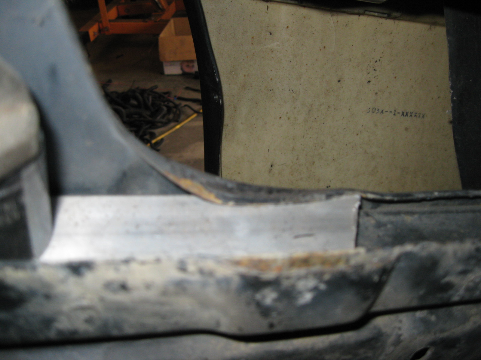
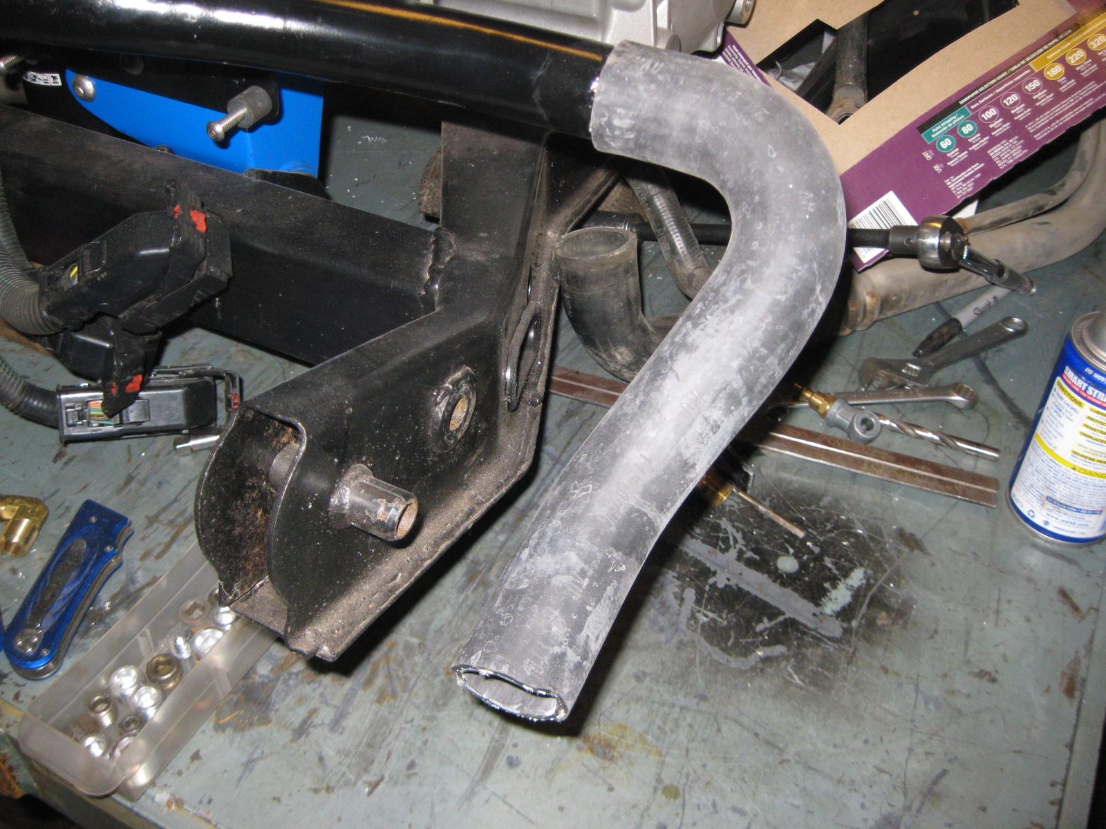
I sanded down the air intake tube for the coating in truck bed liner, but before coating it I needed to tweak the oem hole I am using for it. The intake is very tight with the factory hole and if I don't do something it will scratch when I reassemble it (and it is rather difficult to remove)... so here is how it fits the stock hole (notice it clears the frame rail, but sits on the sheet metal for the hole):
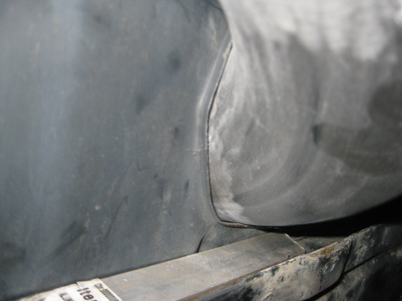
I am going to bend the sheet metal over to re-contour the hole. In the first pic you can see the piece of aluminum I clamped to the frame rail. It was 1/4" thick and very close to elevation of the stock flange at the front of the hole. You can see how much the sheet metal rises as it goes to the rear. With the aluminum there, I can hammer the sheet metal over onto the aluminum to make a new flange.
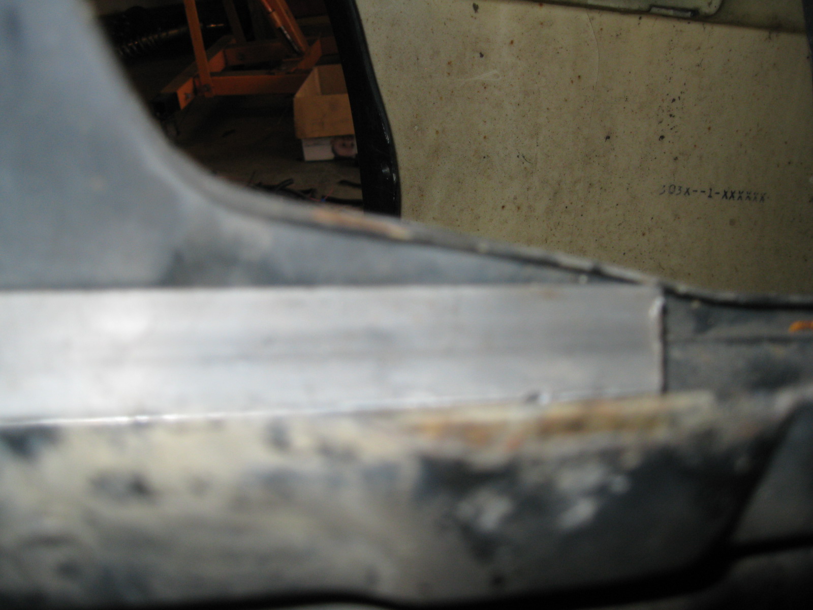
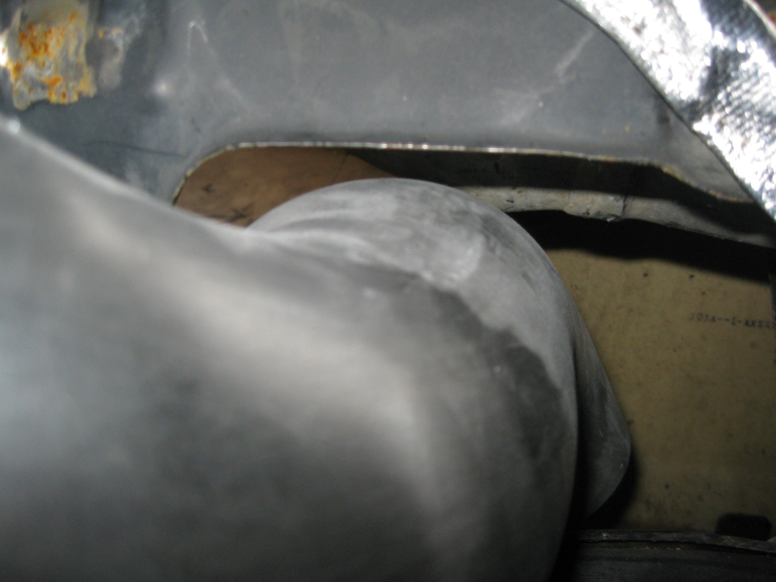
After some hammering:
Now there is a plenty of clearance around the air intake tube. This should help make removal much easier.
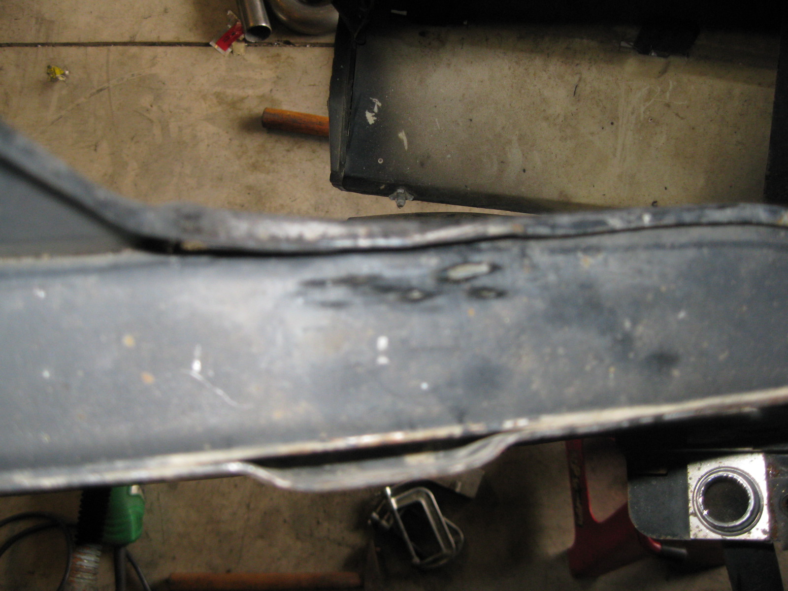
The finishing touch on this mod was to trim the flange back to the stock width.
Also test fitted the stock heater hard line and determined where I would trim the hard line to have a direct shot to the front of the water pump:
I finished the long coolant tube, painted and installed it. Also installed the painted PCV hard line and started reassembling everything I had taken apart. Once I install the last 3 hose nipples (heater hose, steam hose, brake booster hose) I think the work on the engine/transmission/cradle combo will be done (besides assembling the suspension, but I am not doing that until the engine runs in the chassis).
I sanded down the air intake tube for the coating in truck bed liner, but before coating it I needed to tweak the oem hole I am using for it. The intake is very tight with the factory hole and if I don't do something it will scratch when I reassemble it (and it is rather difficult to remove)... so here is how it fits the stock hole (notice it clears the frame rail, but sits on the sheet metal for the hole):
I am going to bend the sheet metal over to re-contour the hole. In the first pic you can see the piece of aluminum I clamped to the frame rail. It was 1/4" thick and very close to elevation of the stock flange at the front of the hole. You can see how much the sheet metal rises as it goes to the rear. With the aluminum there, I can hammer the sheet metal over onto the aluminum to make a new flange.
After some hammering:
Now there is a plenty of clearance around the air intake tube. This should help make removal much easier.
The finishing touch on this mod was to trim the flange back to the stock width.
Also test fitted the stock heater hard line and determined where I would trim the hard line to have a direct shot to the front of the water pump:
12-09-2012, 05:42 PM
#83
I moved to the front of the car and started to do some more work. First order of business was removing the head lights, glad I did as I found this special gift the previous owner left for me... It didn't go to anything anymore, just a bare end on the wire.
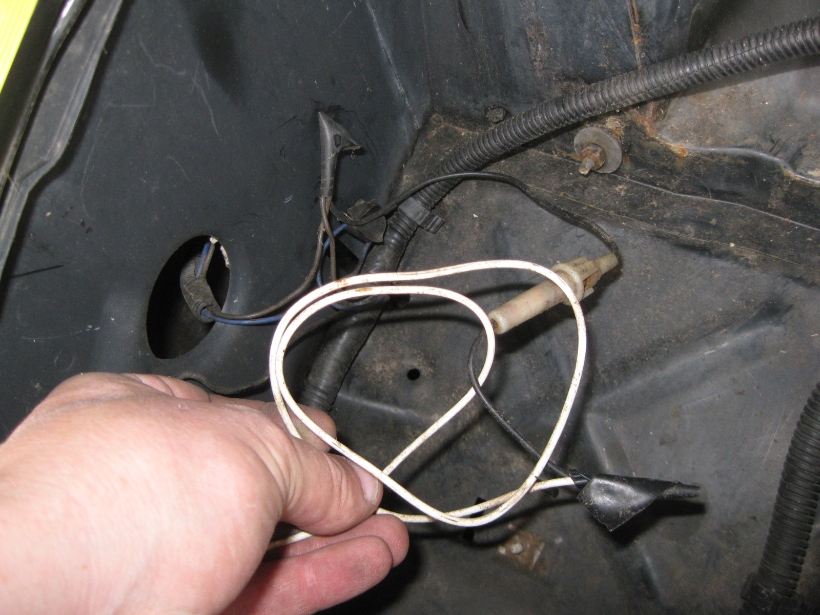
Upon further inspection, found he had cut the blue other wire too...
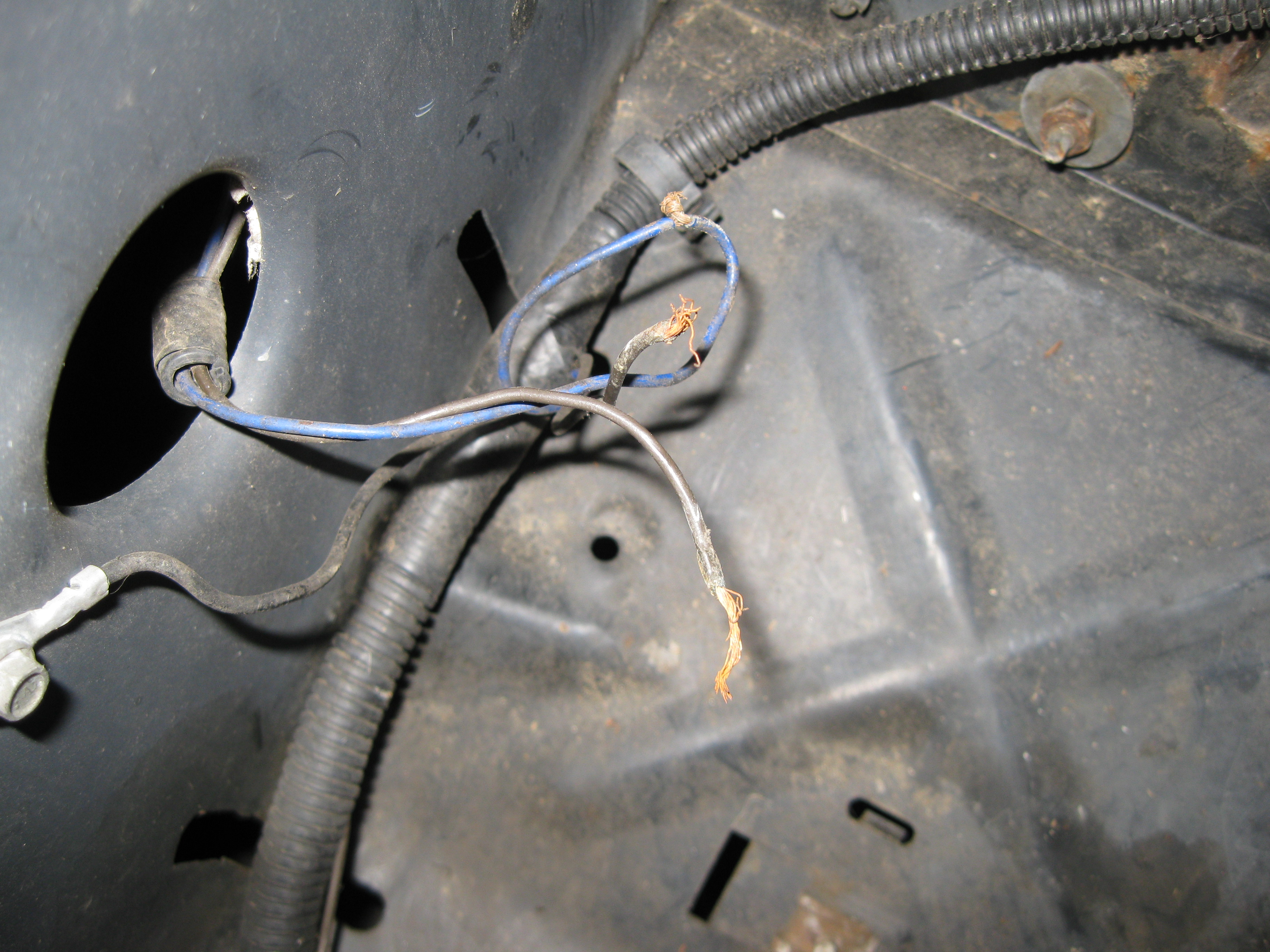
So I had to fix that mess... cut, strip, twist:

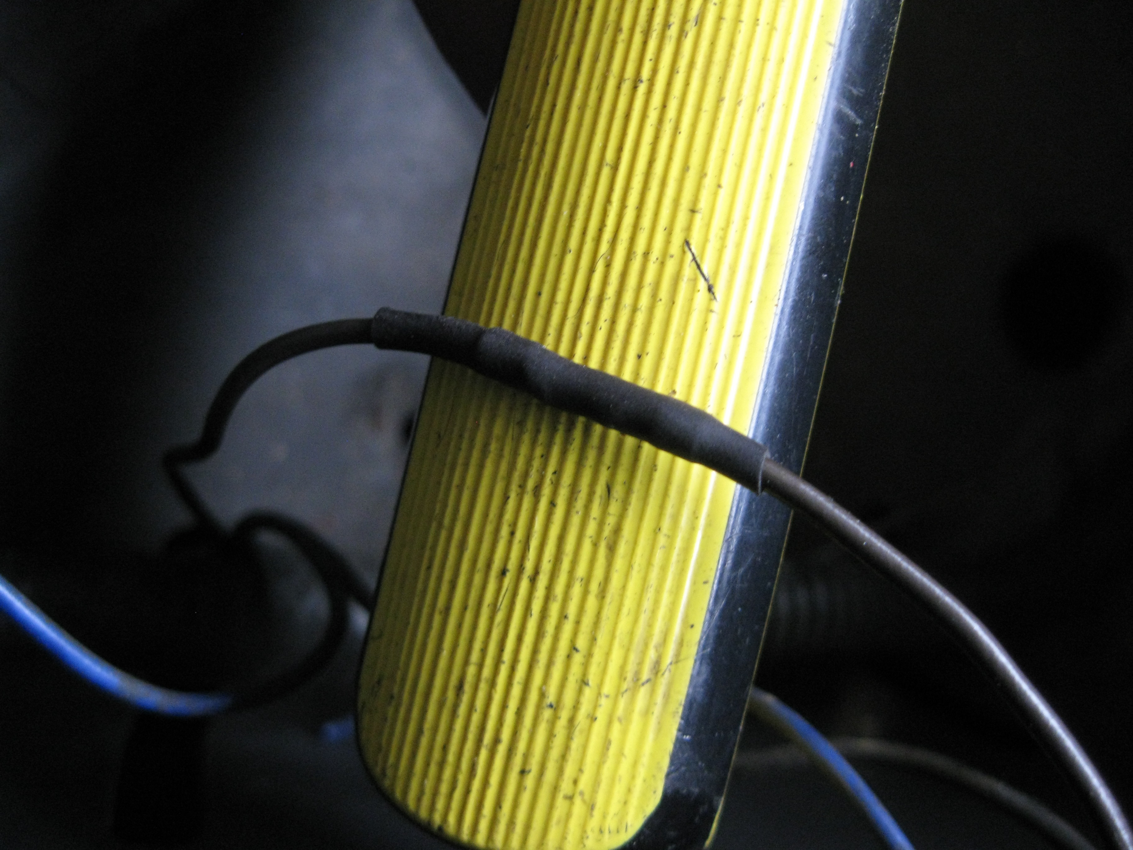
Solder:

Double heat shrink:
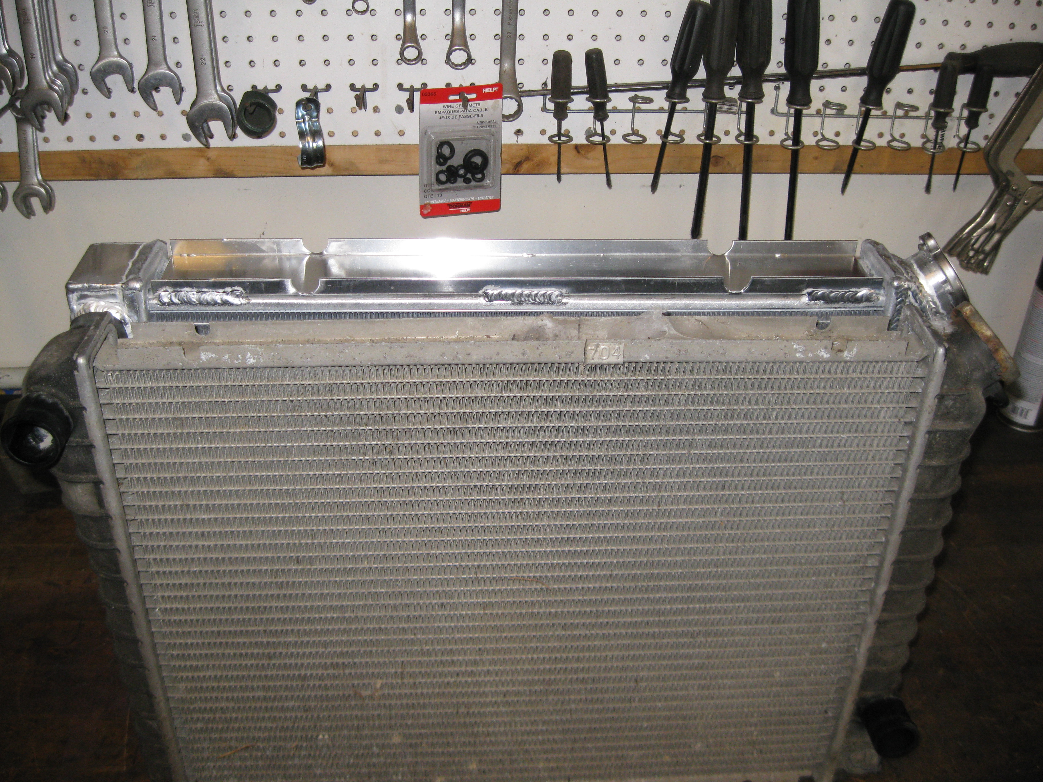
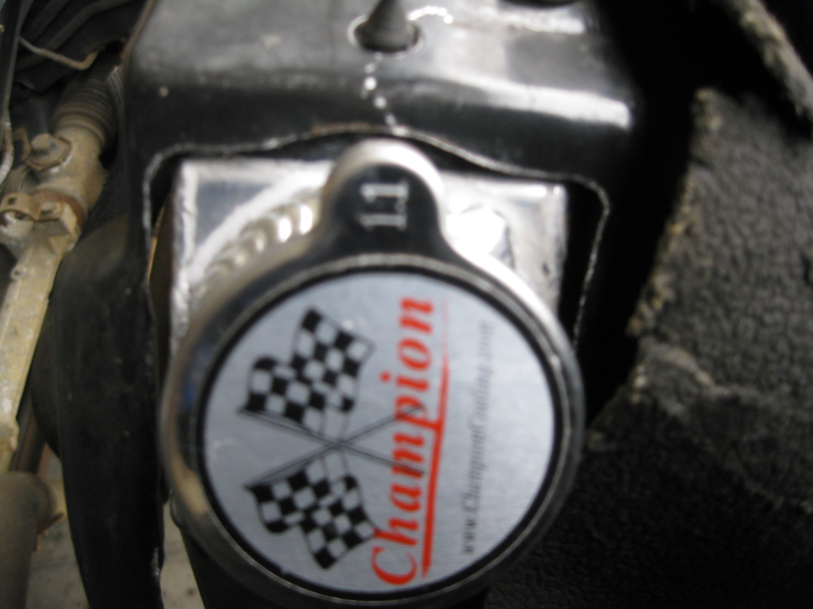
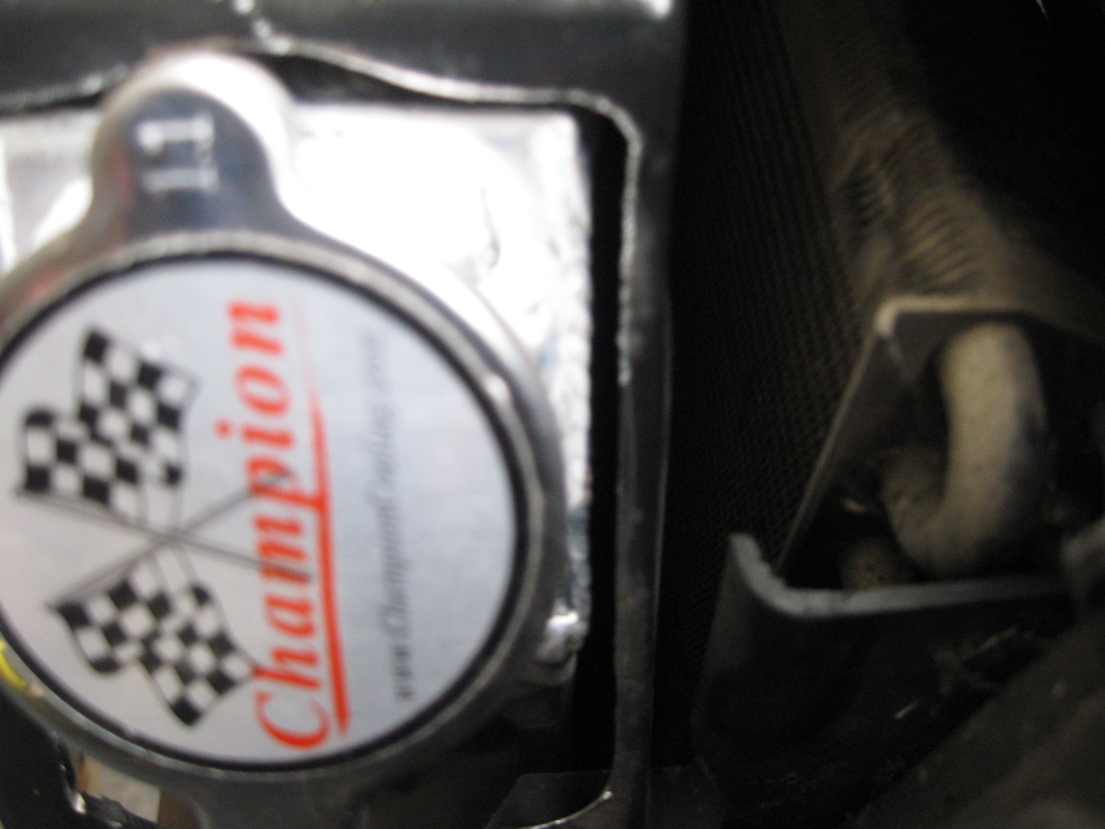
Then I moved on the the radiator upgrade. Here is the Champion one on the left and the stock V6 radiator on the right:
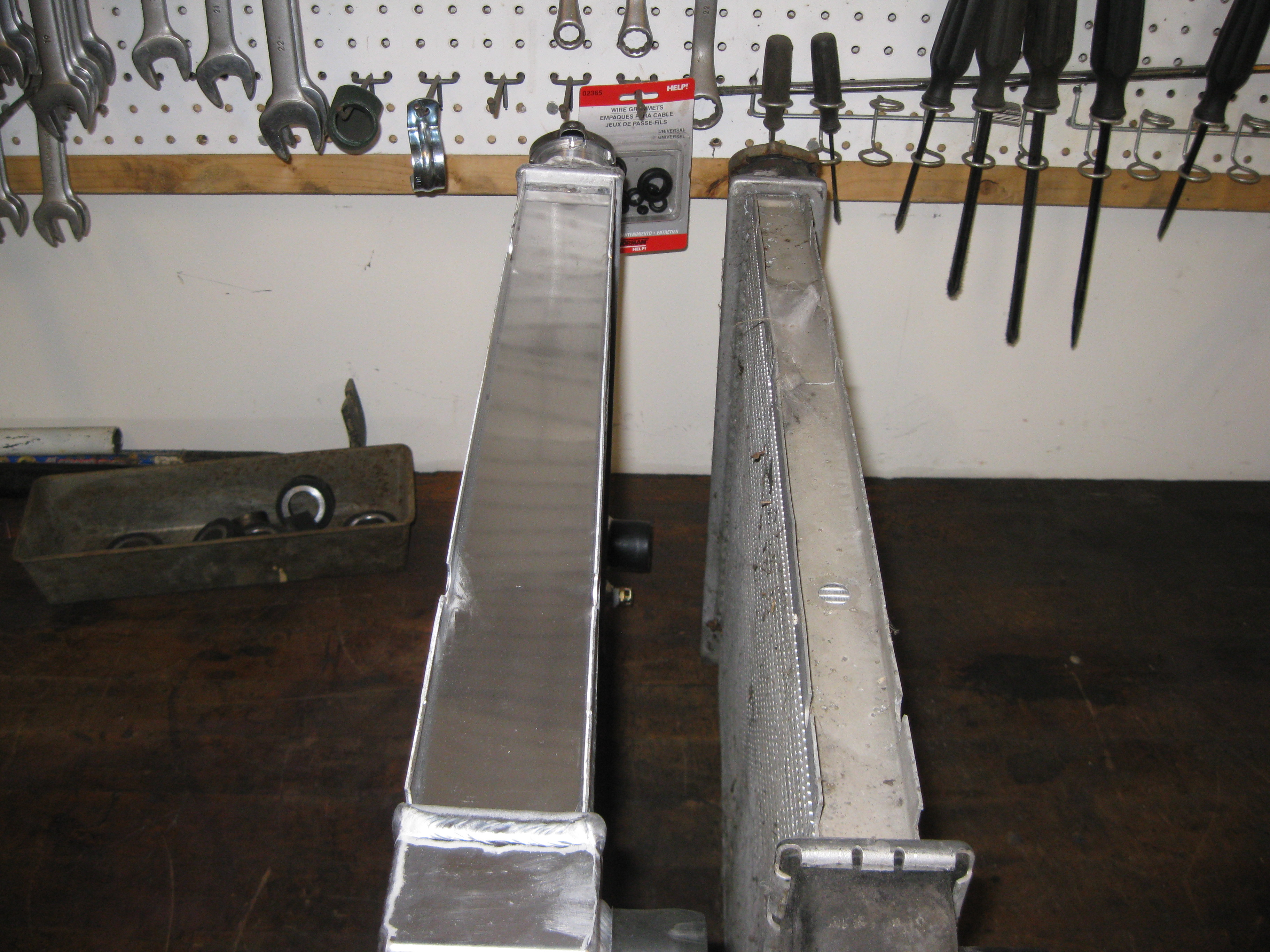
The overall external dimensions are pretty close:
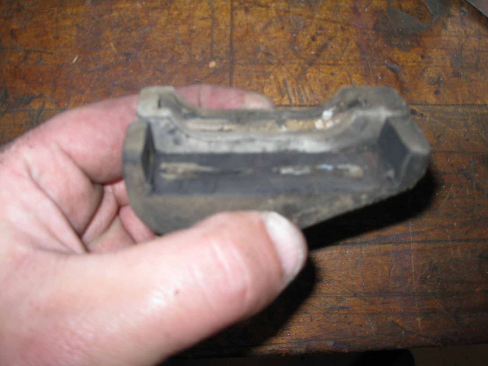
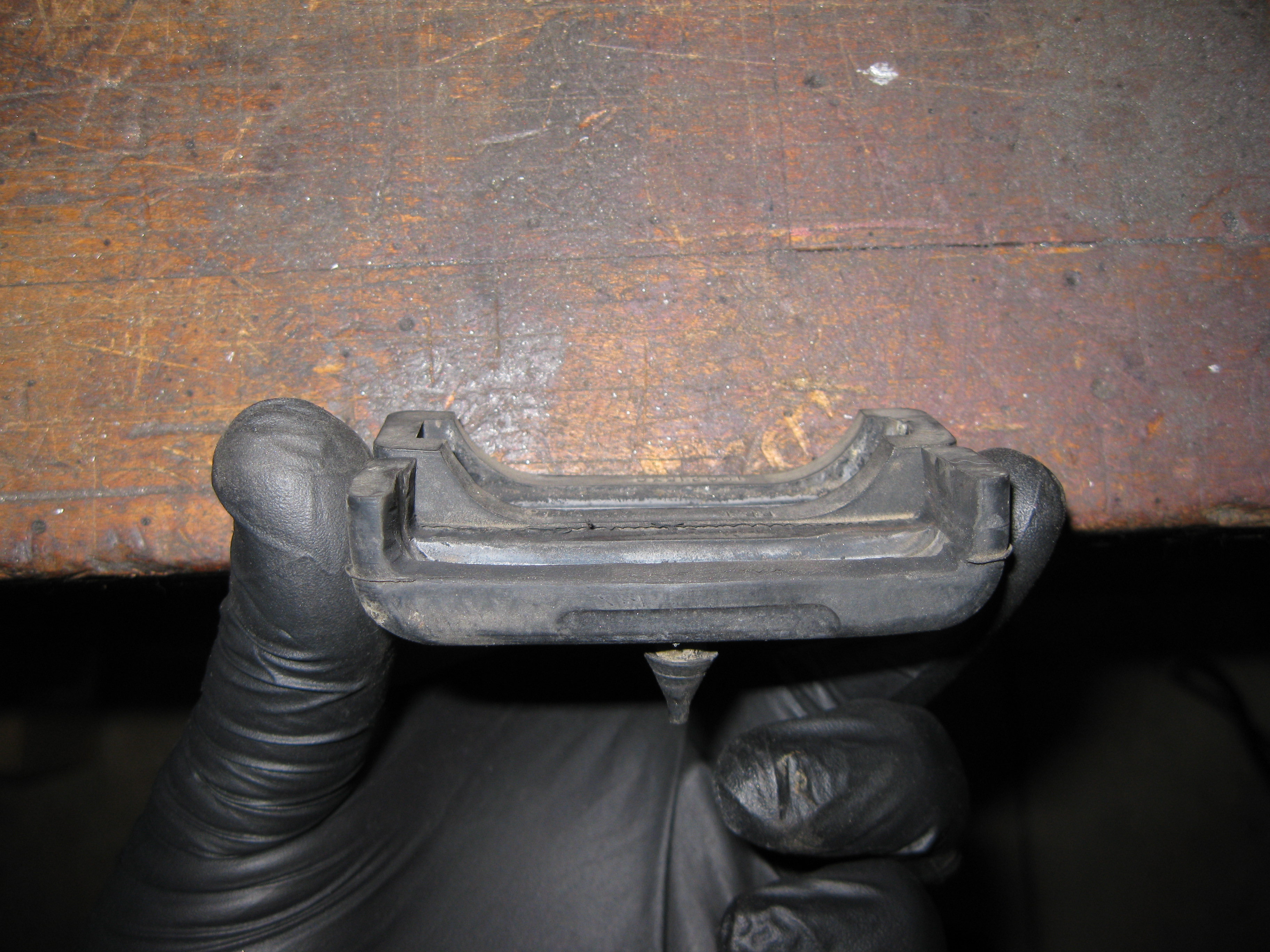
Starting the work on the rubber mounts. Here the stock lower rubber mount showing that the cut out is too small:
So I trimmed it up a bit. Trimmed one in front, stock one in the rear:
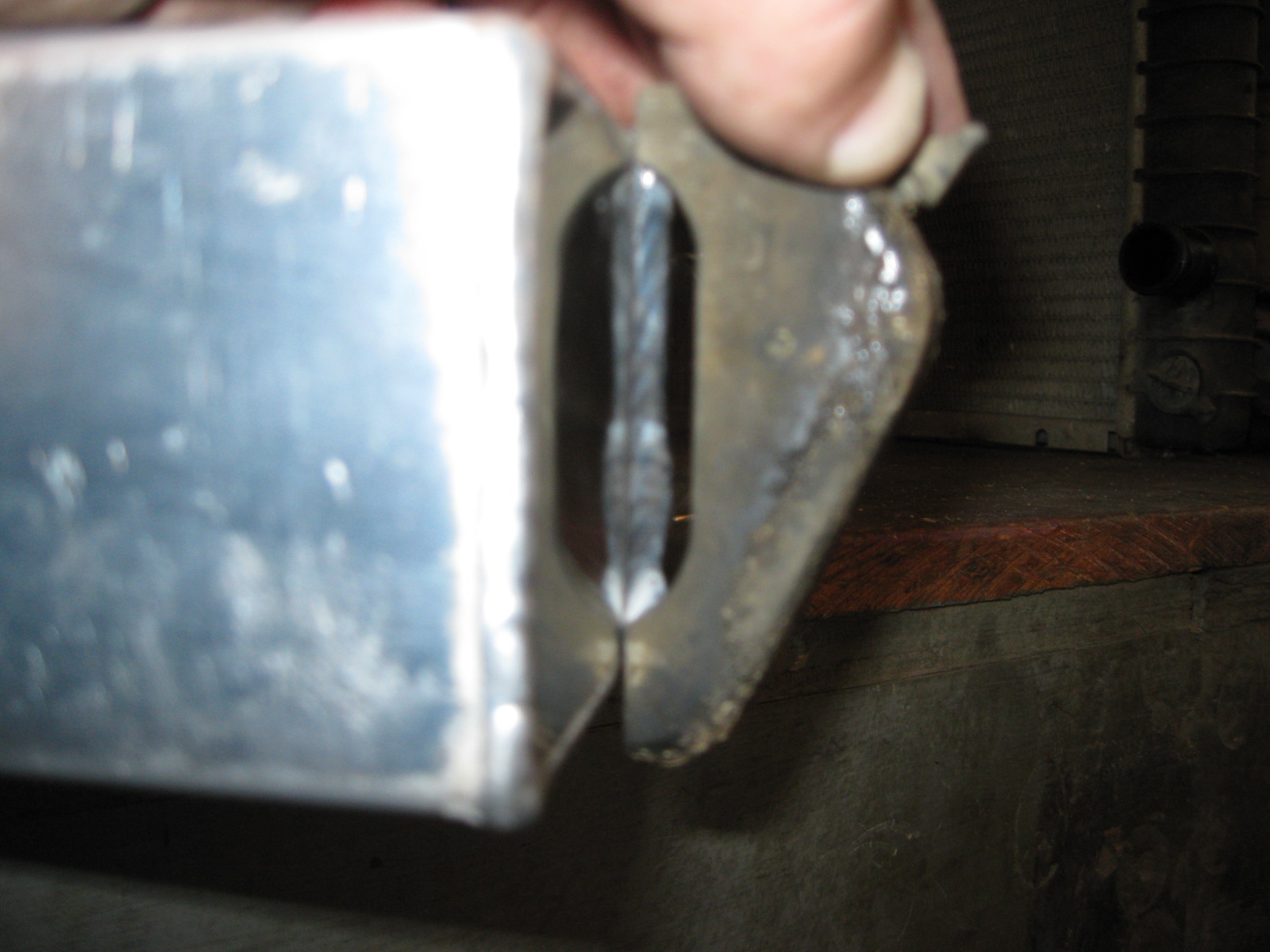
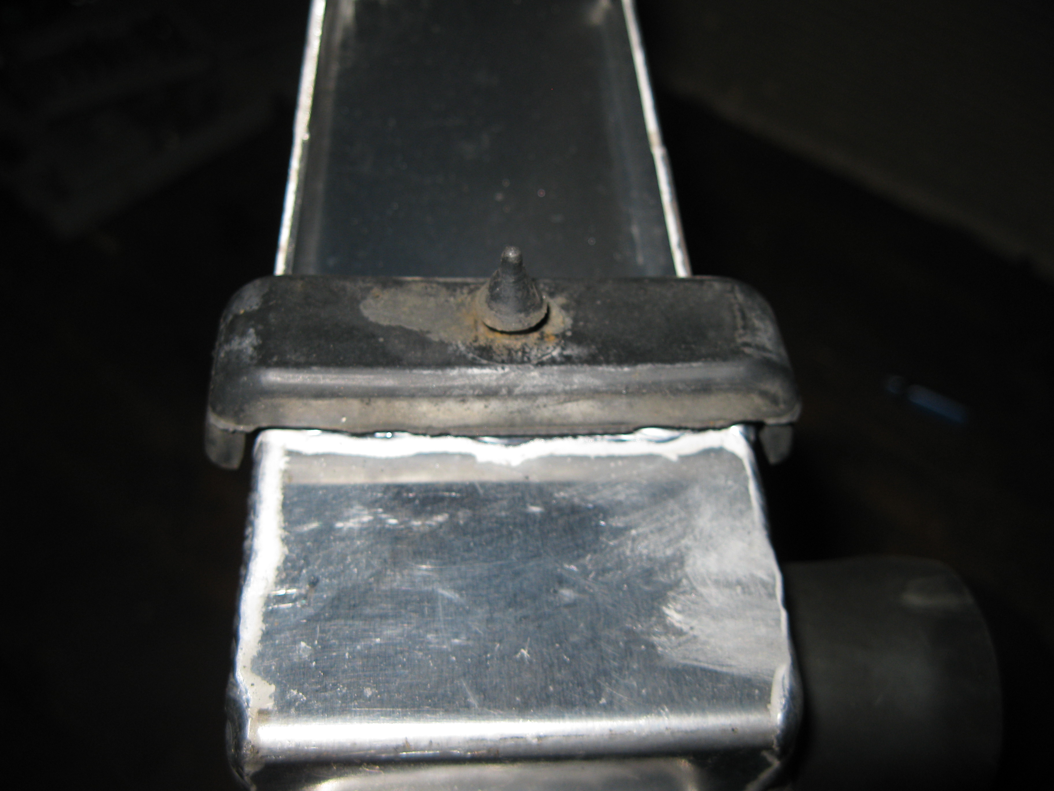
While test fitting the radiator in the modified lower mounts, I found a bolt the protruded enough to make contact with the side cap (the one near the center of the pic):

After a little work with the cutoff disk on the grinder:

Now the radiator sits in the lower base and it is time to start working on the top rubber mounts and top bracket... but ran out of day light (nose of the car is up against the door and the garage doesn't have any lights in the front half by the door...
Upon further inspection, found he had cut the blue other wire too...
So I had to fix that mess... cut, strip, twist:
Solder:
Double heat shrink:
Then I moved on the the radiator upgrade. Here is the Champion one on the left and the stock V6 radiator on the right:
The overall external dimensions are pretty close:
Starting the work on the rubber mounts. Here the stock lower rubber mount showing that the cut out is too small:
So I trimmed it up a bit. Trimmed one in front, stock one in the rear:
While test fitting the radiator in the modified lower mounts, I found a bolt the protruded enough to make contact with the side cap (the one near the center of the pic):
After a little work with the cutoff disk on the grinder:
Now the radiator sits in the lower base and it is time to start working on the top rubber mounts and top bracket... but ran out of day light (nose of the car is up against the door and the garage doesn't have any lights in the front half by the door...
12-15-2012, 02:37 PM
#84
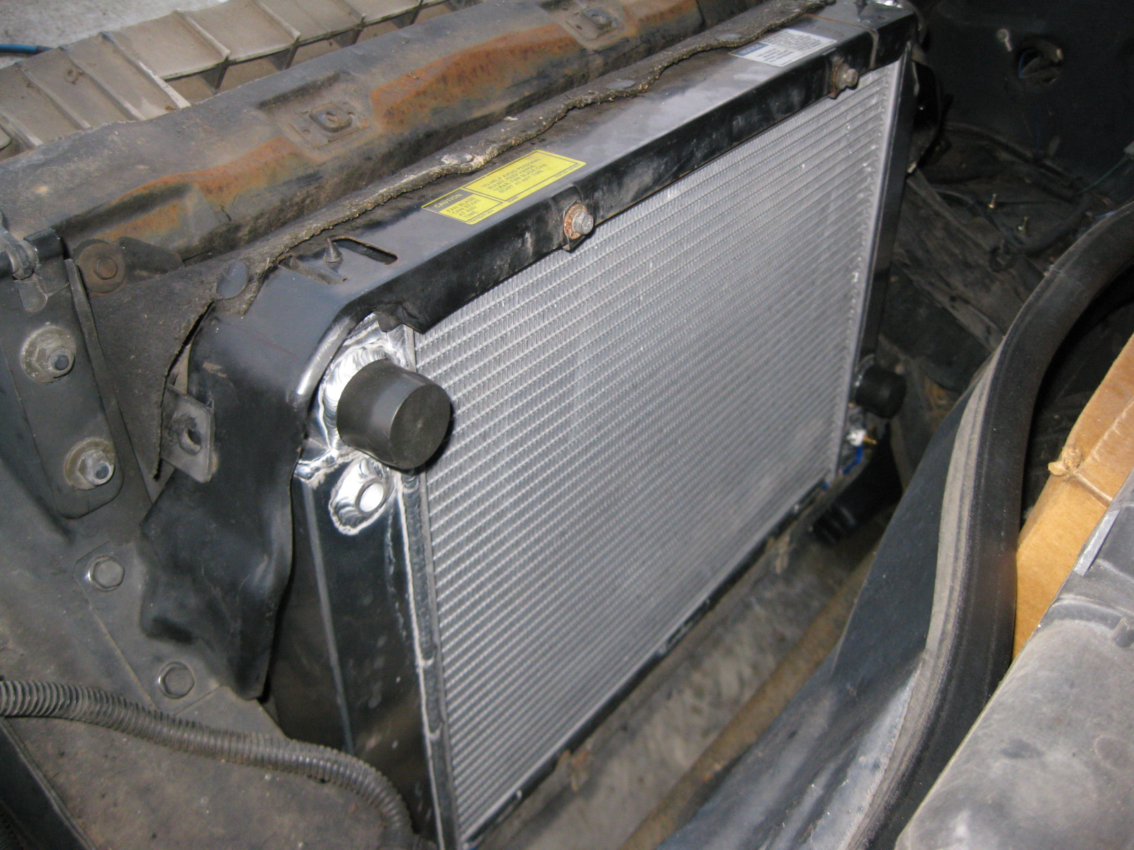
I think the radiator upgrade is now complete. I ended up reshaping the top rubber seats as well (modified one in front, stock one in back):
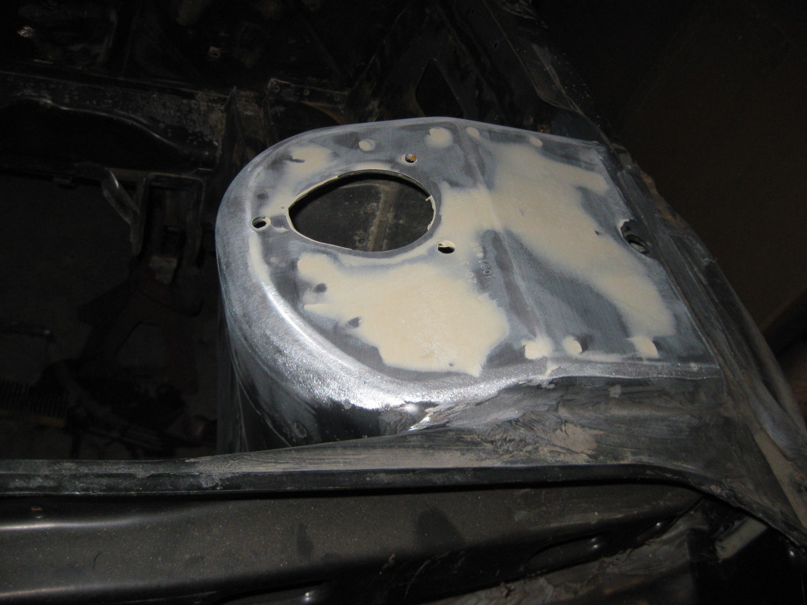
The only modification to the sheet metal was to open up the hole around the fill neck:
I didn't need to do any modifying to the driver side, probably because I was able to slide the radiator over about 1/8" (with the larger fill cut out) to get everything to clear.
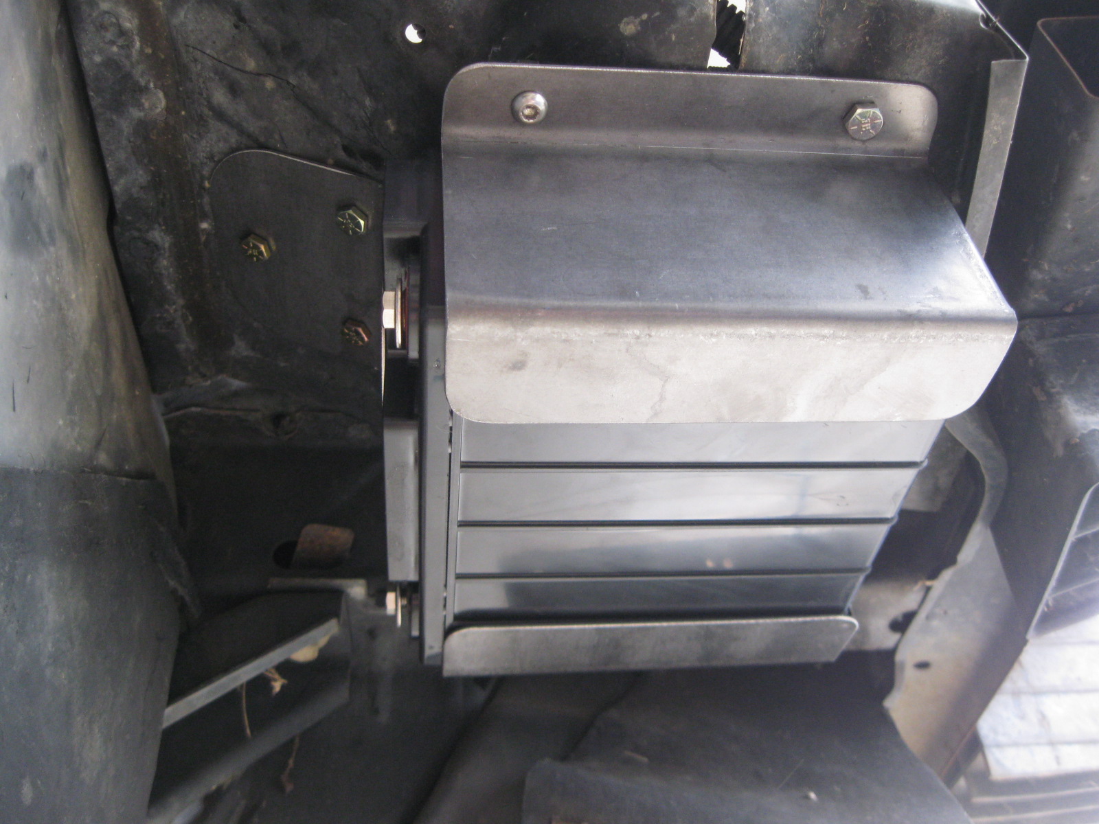
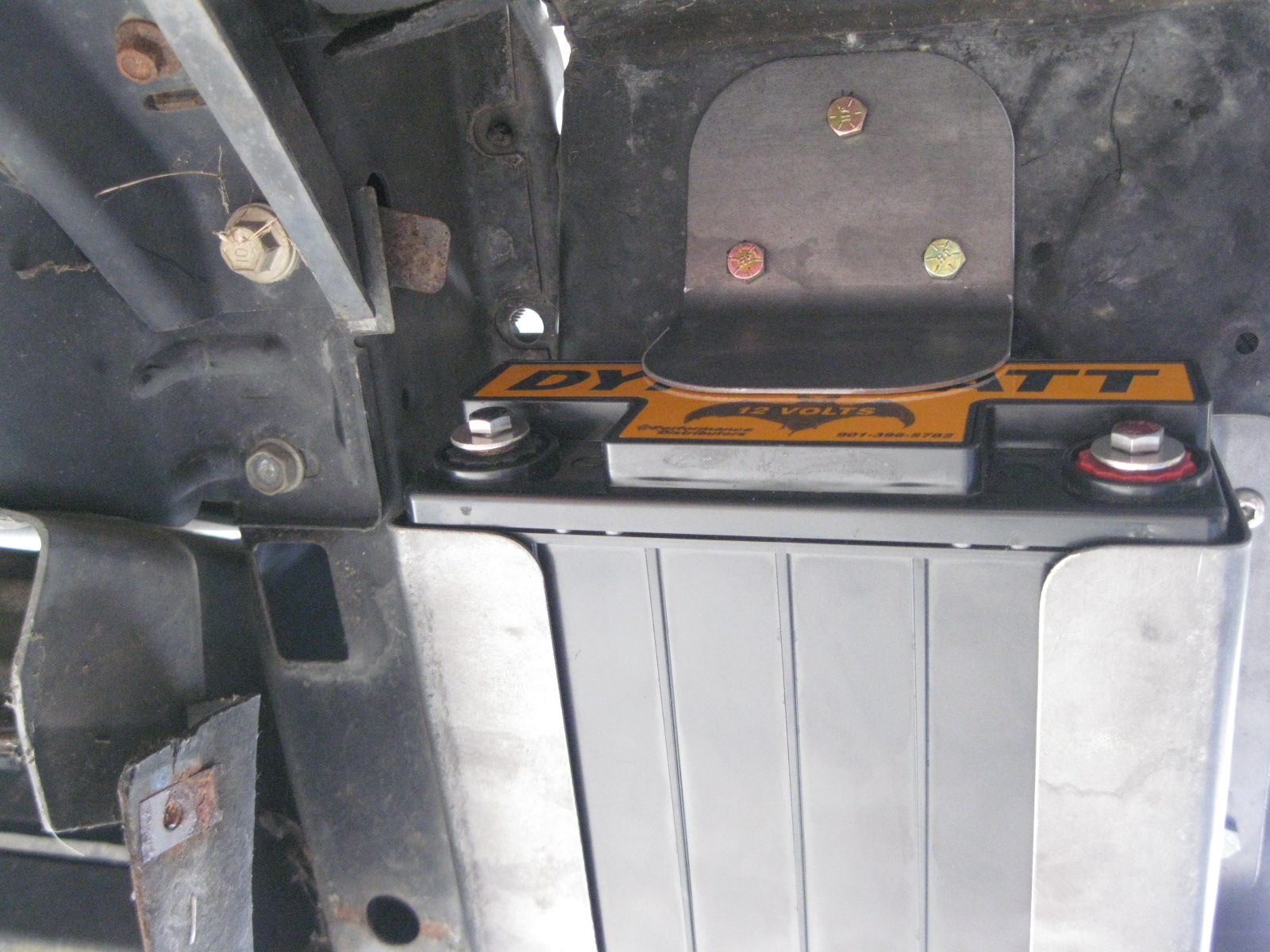
Then I worked on the battery mount. I fabbed up these brackets to hold the battery, but ended up unbending one of the bolted flanges.
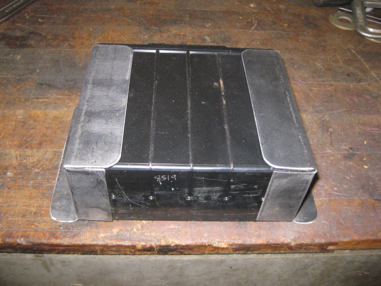
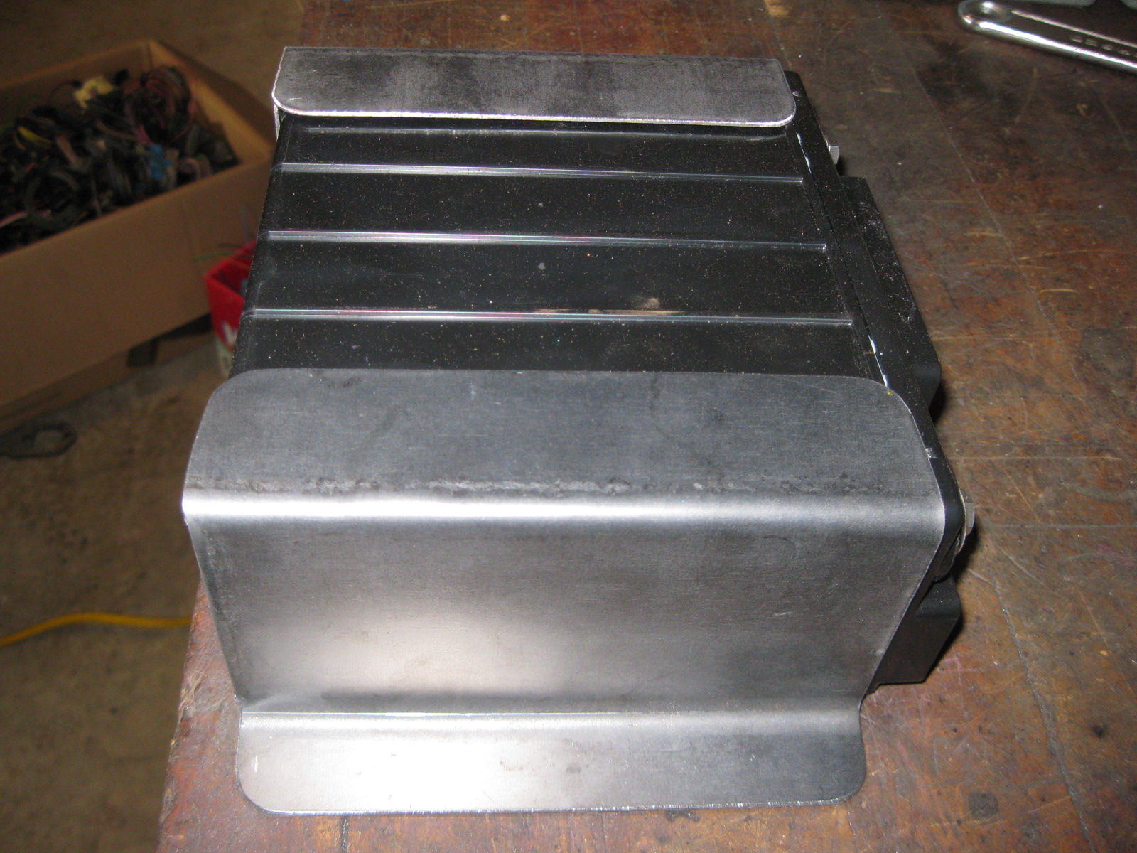
The battery is now mounted under the passenger head light, but the only modification to the sheet metal in that area was to drill seven 1/4" holes. In the first picture you can see that the battery easily clears the bottom of the 88 coupe fascia (notice the 2 bolt air ducting bracket on the other side of the battery).
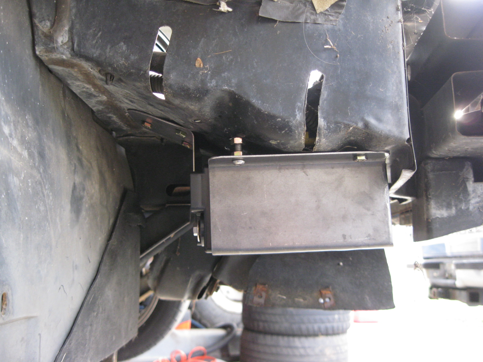
The mounting bracket holds the battery firm in 3 directions and the batter hold down tab secures it in the 4th direction.
The only modification to the sheet metal was to open up the hole around the fill neck:
I didn't need to do any modifying to the driver side, probably because I was able to slide the radiator over about 1/8" (with the larger fill cut out) to get everything to clear.
Then I worked on the battery mount. I fabbed up these brackets to hold the battery, but ended up unbending one of the bolted flanges.
The battery is now mounted under the passenger head light, but the only modification to the sheet metal in that area was to drill seven 1/4" holes. In the first picture you can see that the battery easily clears the bottom of the 88 coupe fascia (notice the 2 bolt air ducting bracket on the other side of the battery).
The mounting bracket holds the battery firm in 3 directions and the batter hold down tab secures it in the 4th direction.
12-15-2012, 04:48 PM
#85
I forgot to take a pic of the radiator with it installed:
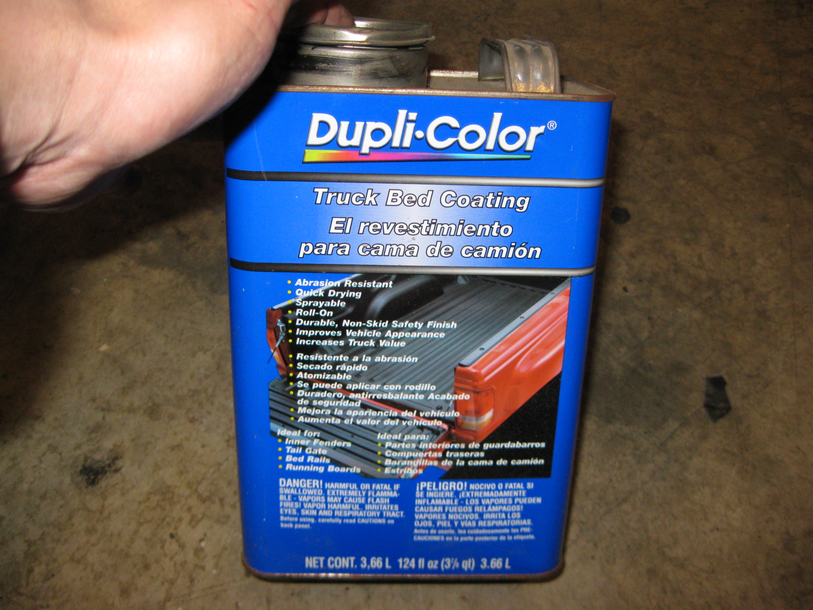
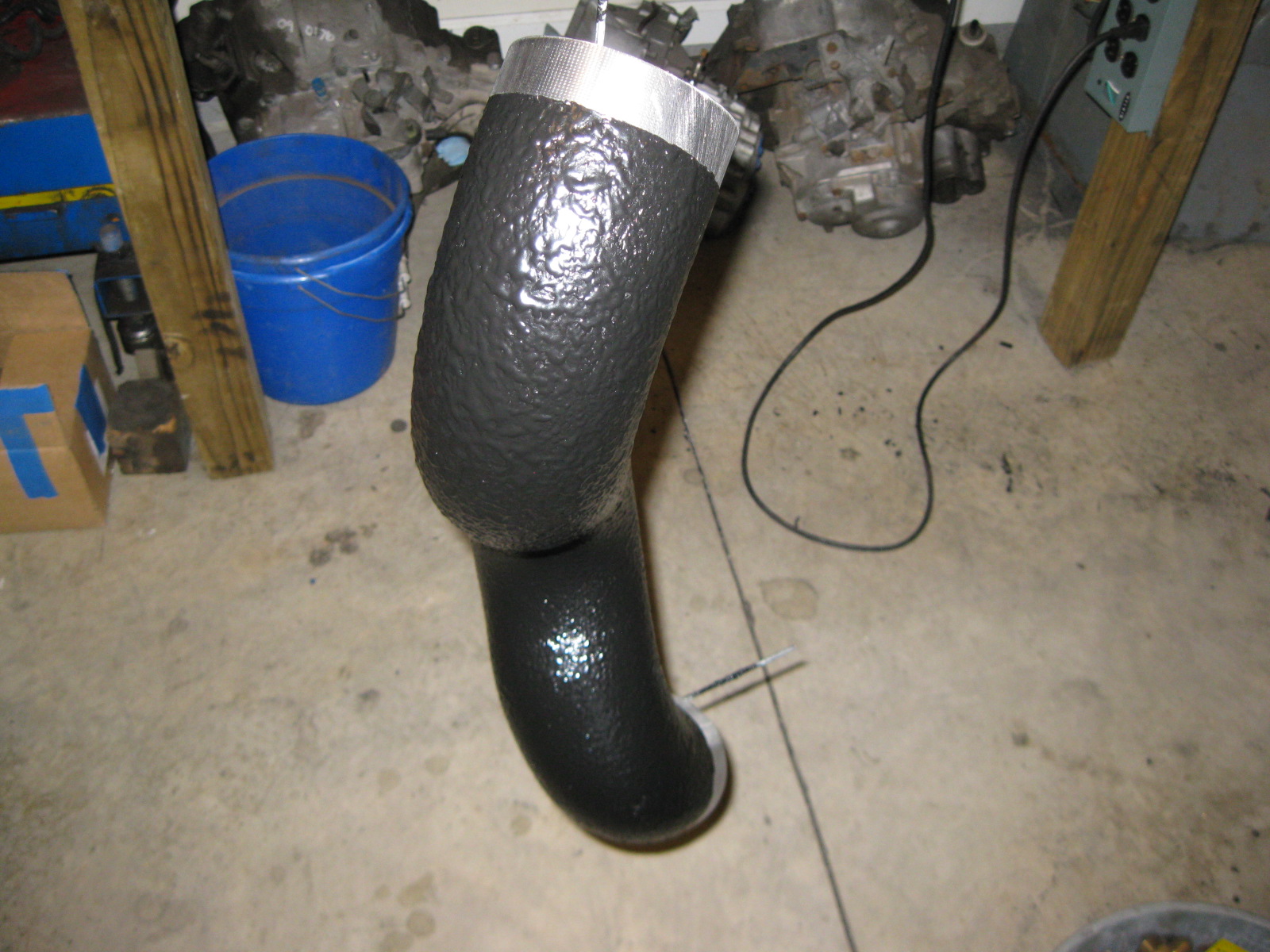
Used some truck bed liner to coat the outside of my cold air intake. This helps to insulate it, as well as masking any weld imperfections:
Also added the last two hose barbs for the coolant system. The small one is post-thermostat and is for the hose from the steam ports on the heads (it normally dumps to the top of the radiator, but post thermostat is pretty much the same. The larger hose barb is pre-thermostat and is for the supply hose to the heater core. The hose for this will run underneath the main hose coming off the thermostat housing:
12-23-2012, 05:44 PM
#87
Been slacking.... but finally spent some time in the garage.
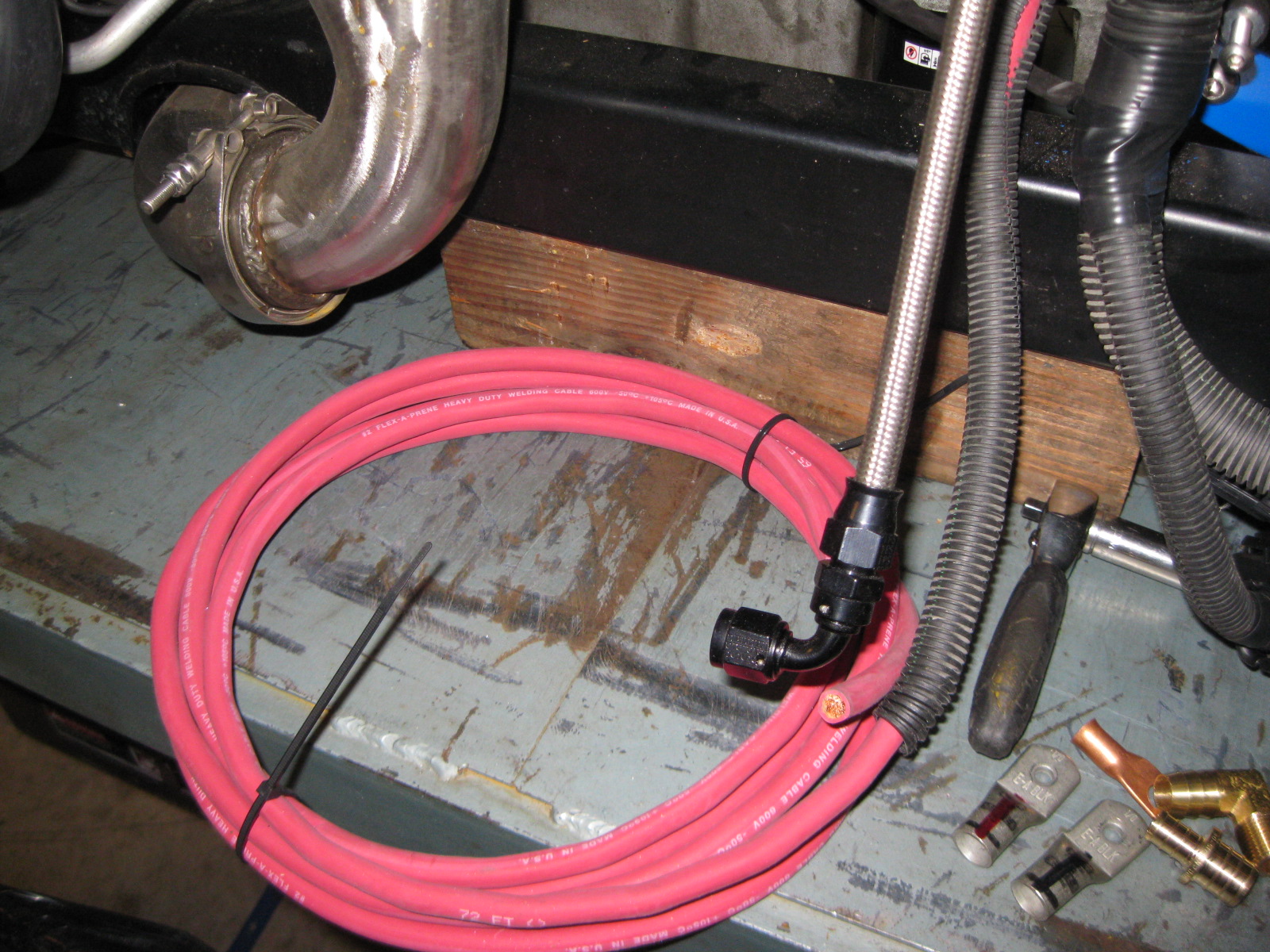
I soldered on the battery cable end at the starter, routed the power cable around the starter and then coiled up the excess. I will run the cables on the final install.

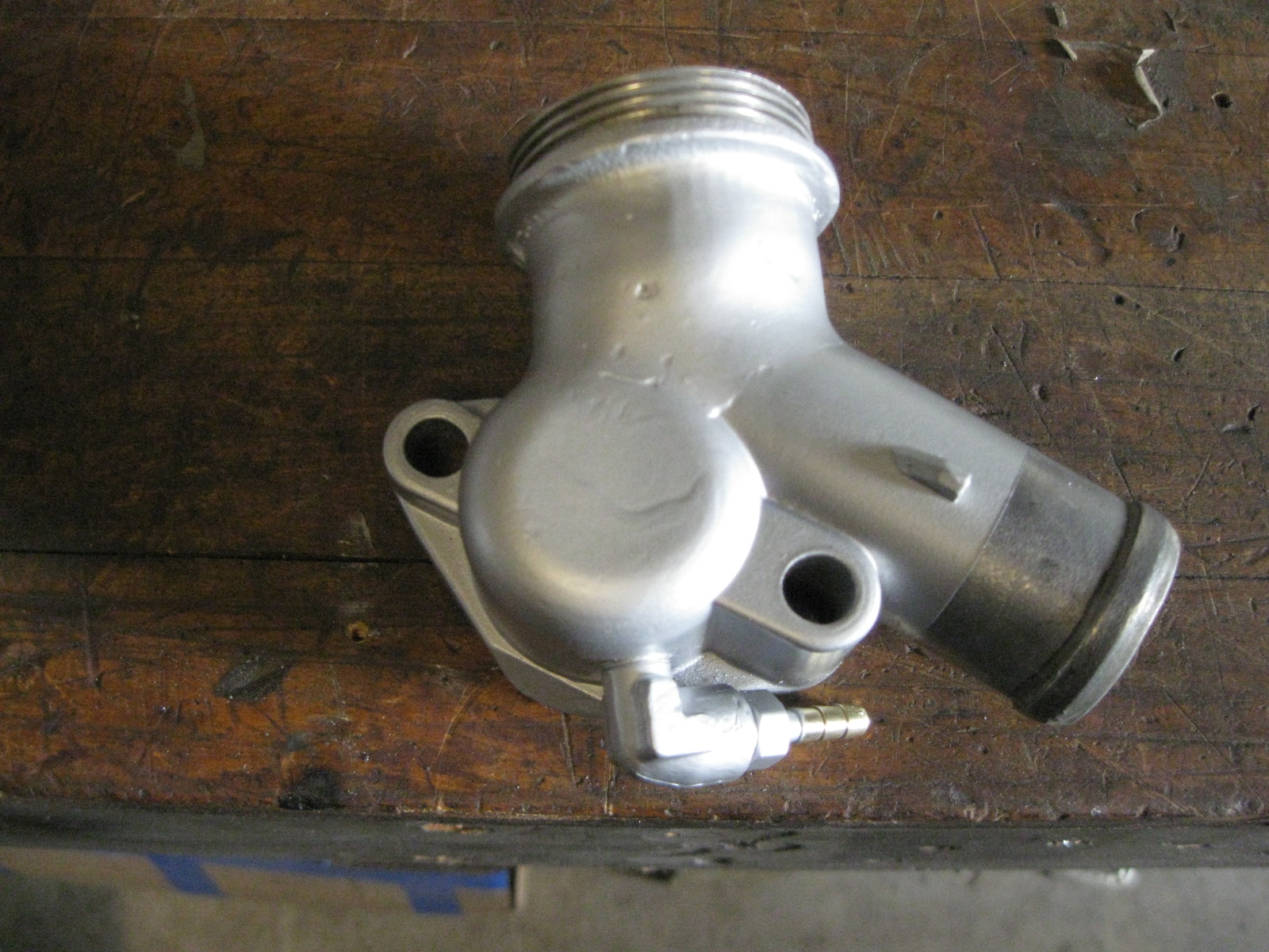
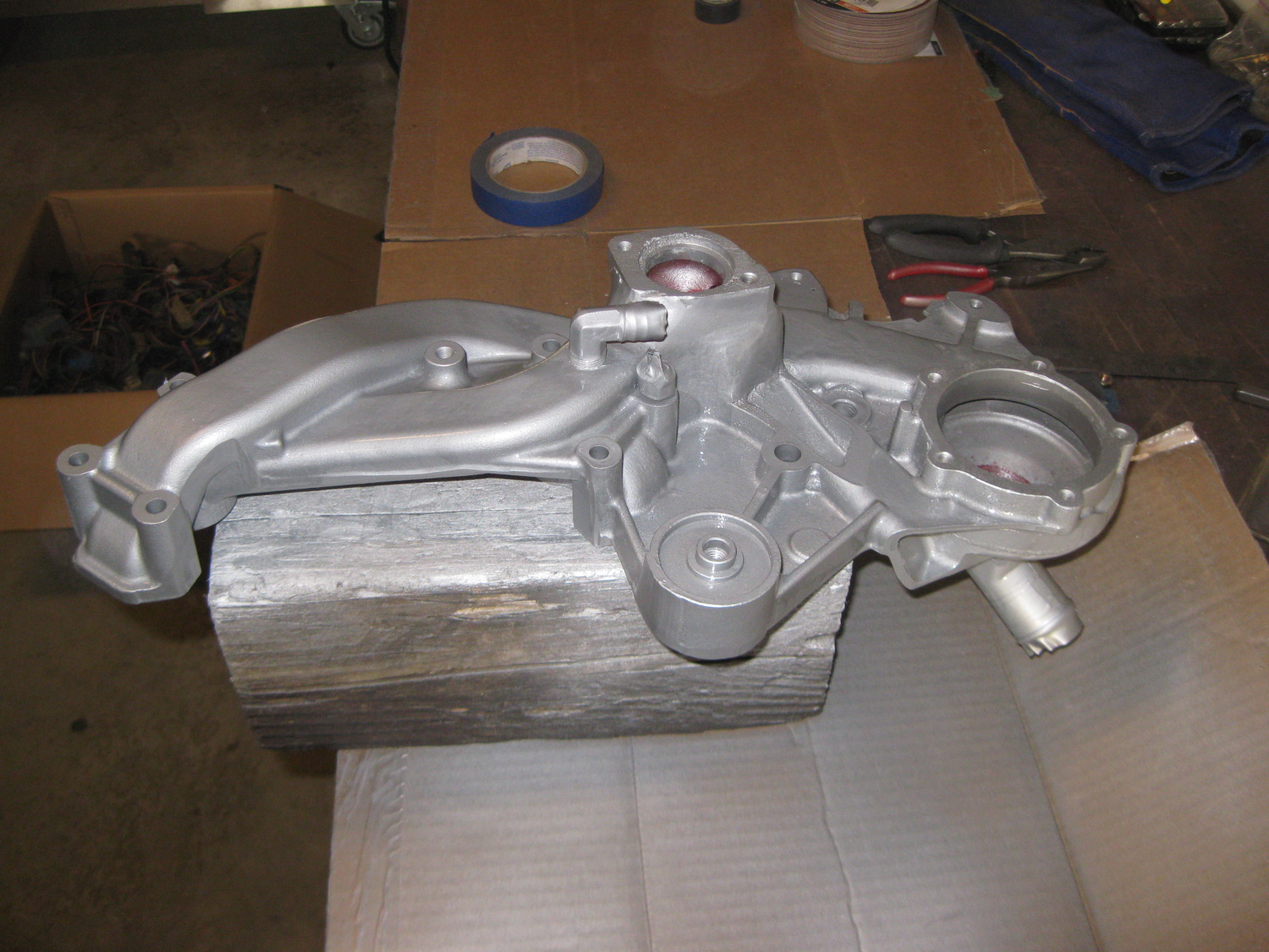
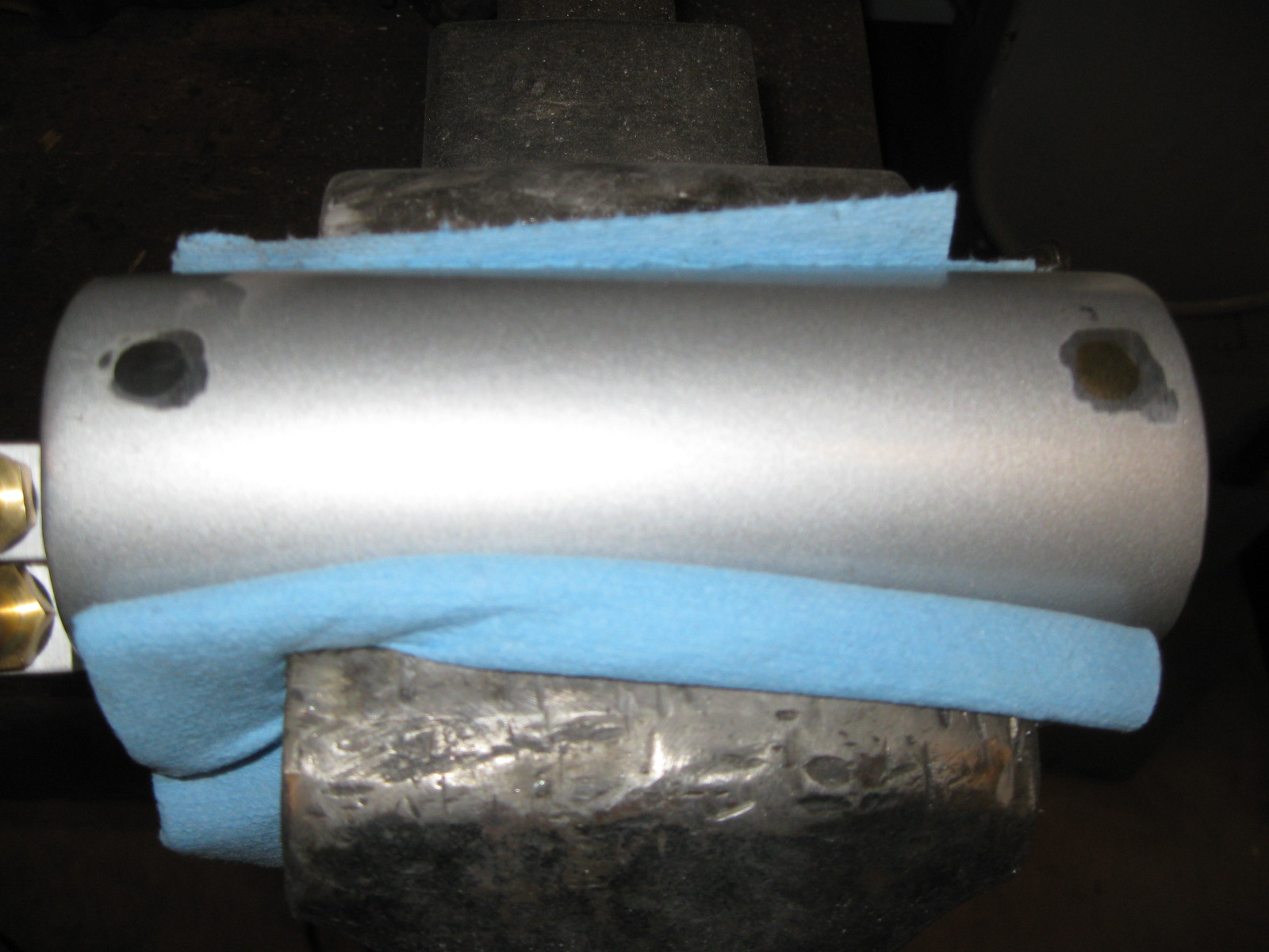
Then I removed the water pump and thermostat housing and painted them aluminum so they would have a more uniform look:

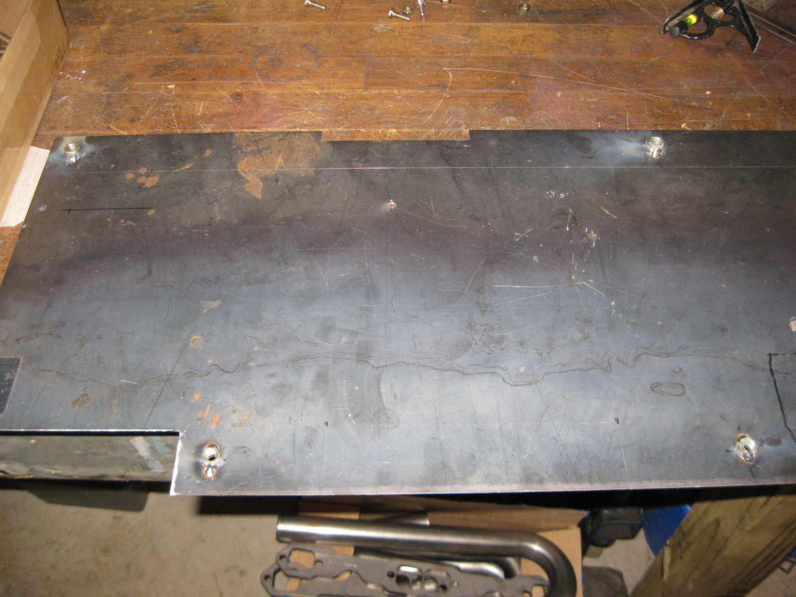
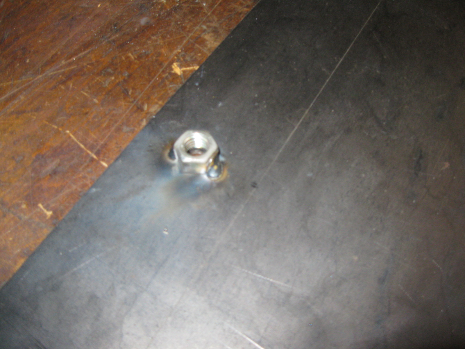
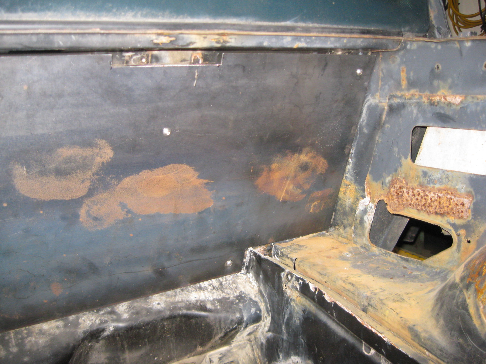
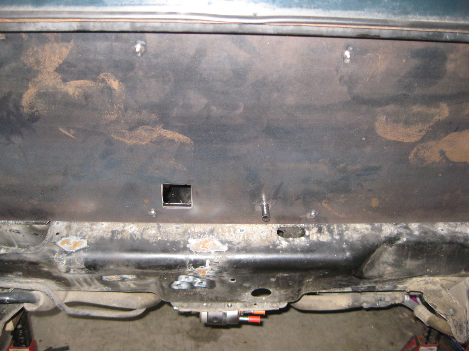
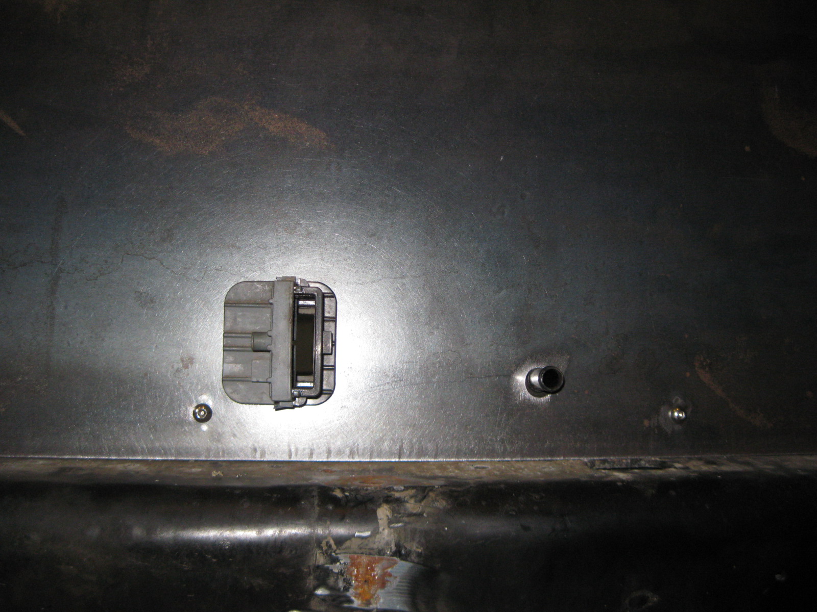
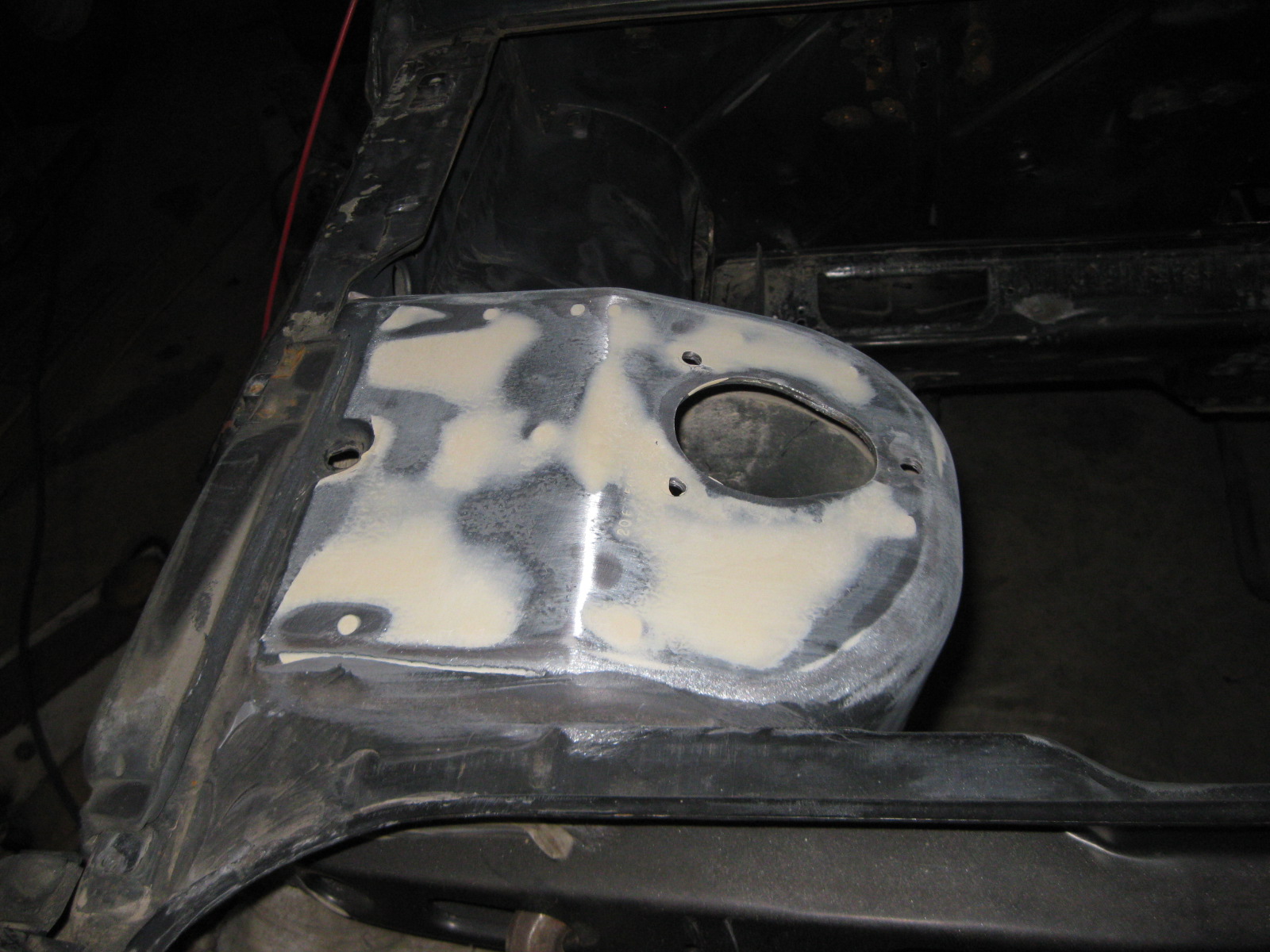
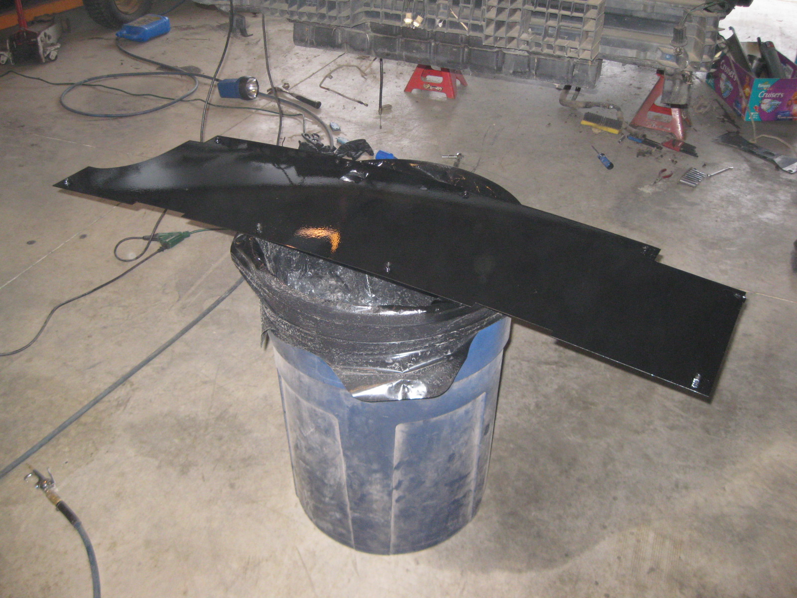
Then I started playing with the smooth firewall panel. I tacked some 3/8" nuts to the backside to space it from the stock firewall, then drilled the 1/4" mounting holes for the bolts and cut the hole for the harness connector:
Now I get to clean the engine bay and sand/prep it for paint!
I soldered on the battery cable end at the starter, routed the power cable around the starter and then coiled up the excess. I will run the cables on the final install.
Then I removed the water pump and thermostat housing and painted them aluminum so they would have a more uniform look:
Then I started playing with the smooth firewall panel. I tacked some 3/8" nuts to the backside to space it from the stock firewall, then drilled the 1/4" mounting holes for the bolts and cut the hole for the harness connector:
Now I get to clean the engine bay and sand/prep it for paint!


 12-24-2012, 09:45 PM
#90
This is one of my favorite threads on this site. The awesome thing is you have done everything yourself.
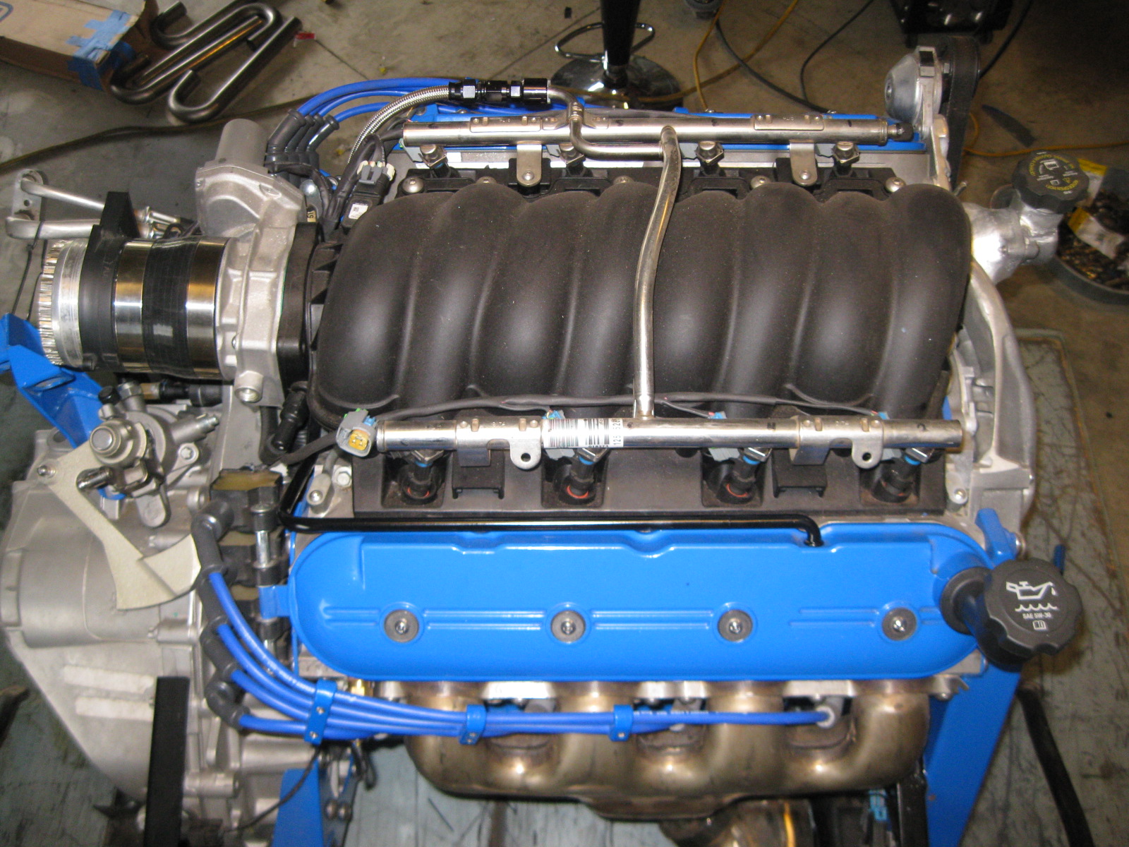
I saw that you put the PCV line on the bottom of the intake tube. Any concern with the oil mist vapor pooling in the bottom of the hose? IIRC everyone I have seen either comes in from the top or the side.
Am I looking at this correctly?
Awesome job!
I saw that you put the PCV line on the bottom of the intake tube. Any concern with the oil mist vapor pooling in the bottom of the hose? IIRC everyone I have seen either comes in from the top or the side.
Am I looking at this correctly?
Awesome job!
12-25-2012, 08:40 AM
#91
Thanks for the compliments! Doing all the work myself is the only way I can fund this project... Even with all that, this project is still getting very close to $7K at its current stage (including engine, transmission, HP tuners, the car and all the parts/materials). I am hoping the finished car with wheels, tires and paint comes in between $10-$11K with the expense spread across 3 years.
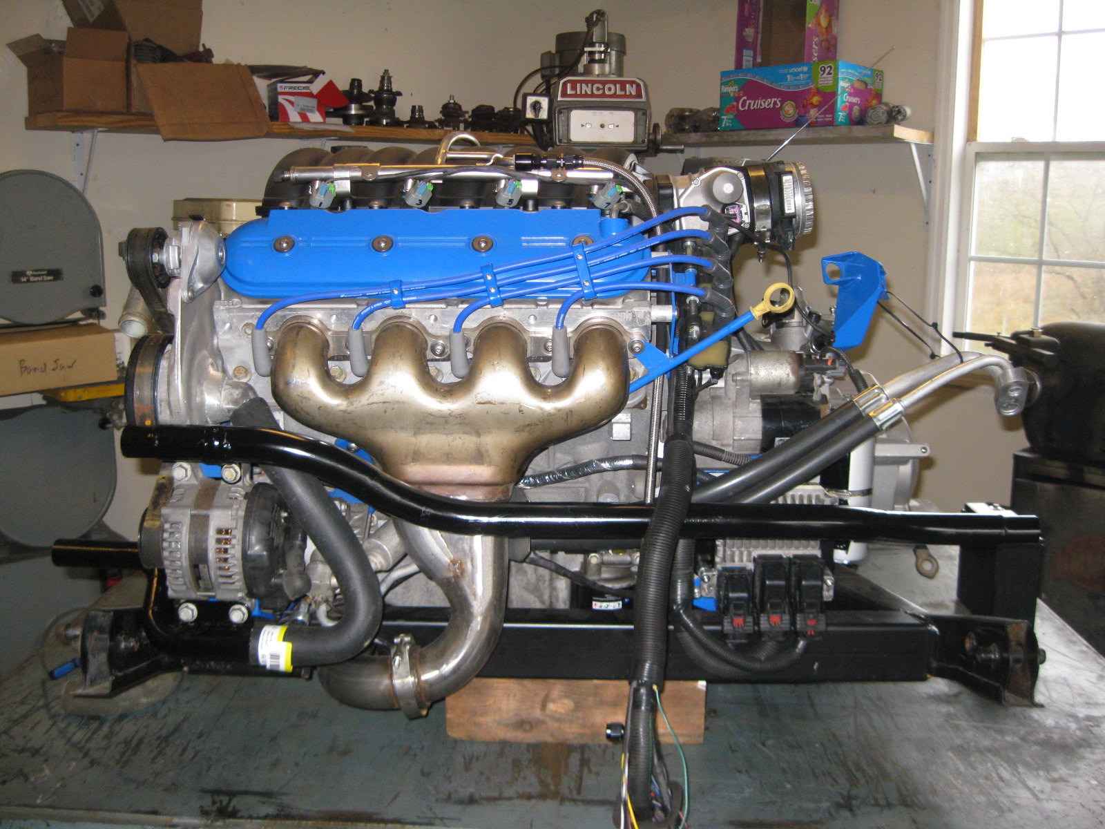
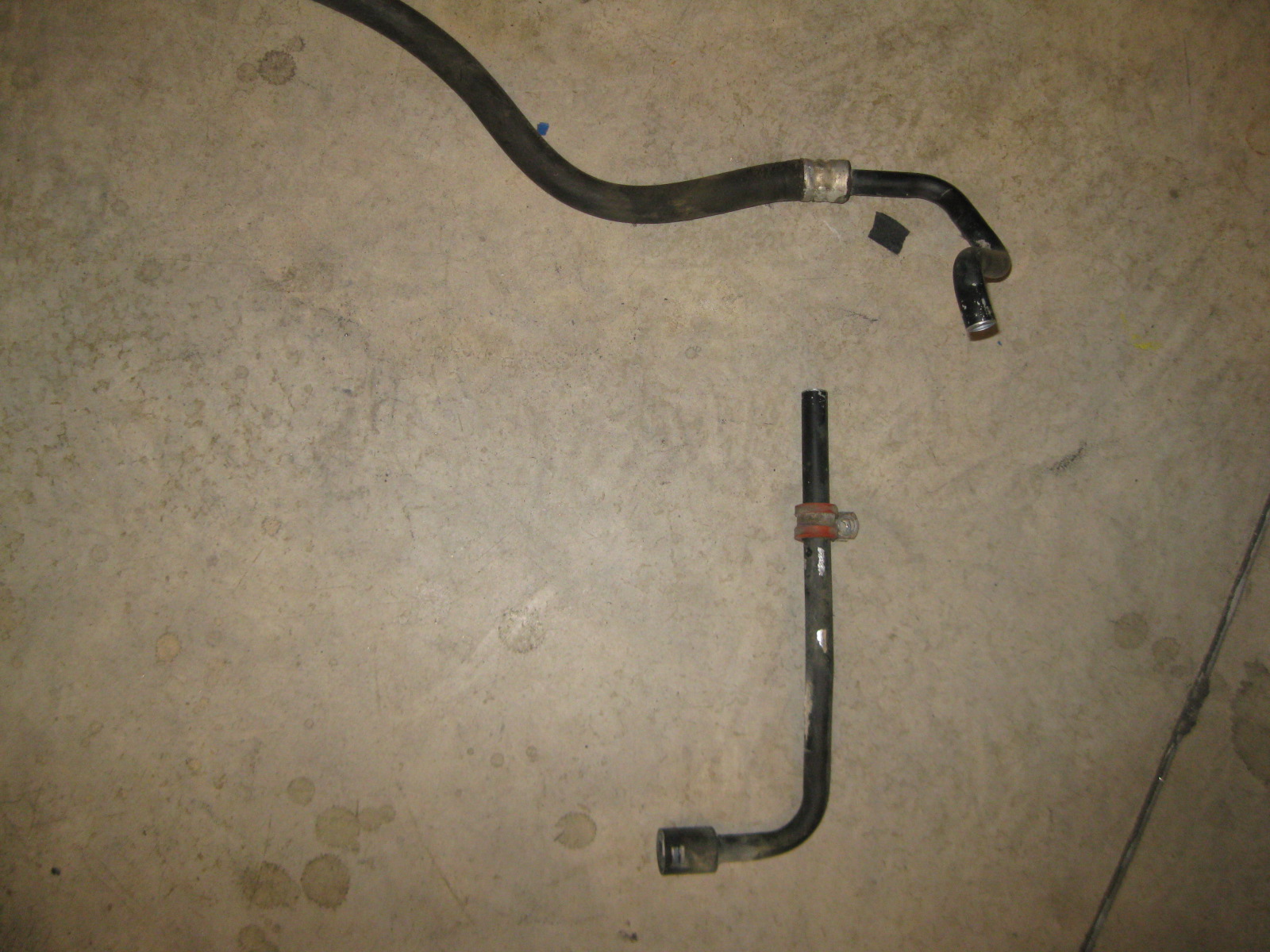
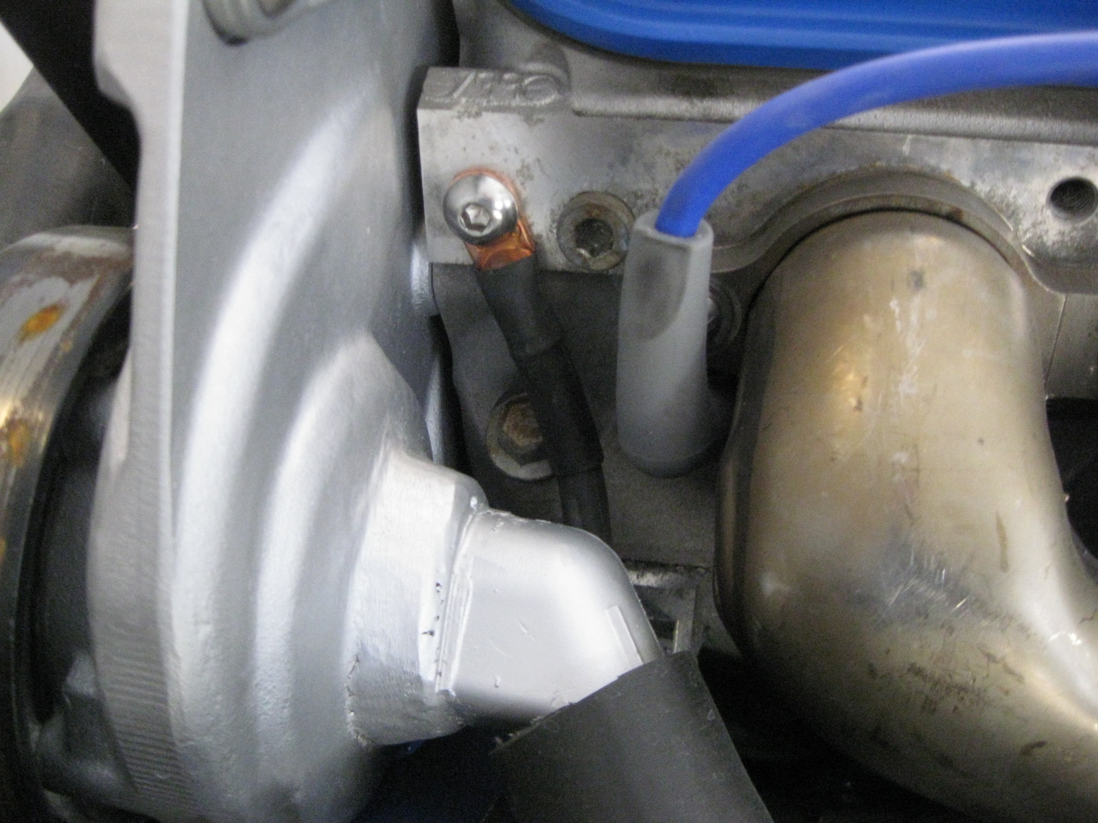
Once I finished the hard line, the nipple in the silicone coupler was moved to the side:

However, the hose/line still has a low spot that could allow oil to collect from any oil mist. This line is the fresh air supply and at anything but WOT the line should be under vacuum pulling air into the valve cover (unless AFM activation for long times changes things - like some air seeping past the rings).
At WOT there is a chance it will push air from the valve cover into the intake tract. If I see this happening, I will probably install an in-line check valve to eliminate the reverse air flow under WOT.
The dirty side goes through a catch can, so I shouldn't get much oil into the intake from that side.

 12-29-2012, 03:34 PM
#96
Thanks for the compliments!
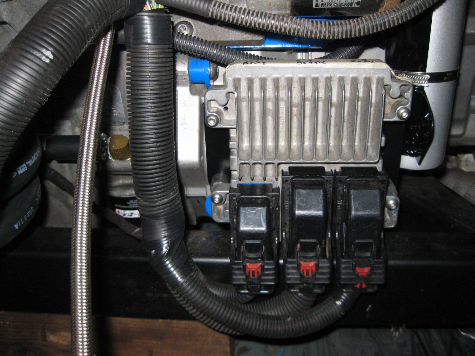
The ECM and TCM are back with the stock 2007 LS4/4T65e-hd calibration loaded on them. In a week or two I will have to spend some quality time with HP tuners and do all the baseline calibration changes to this thing will actually start.
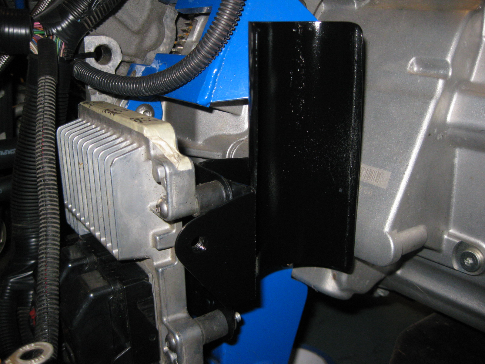
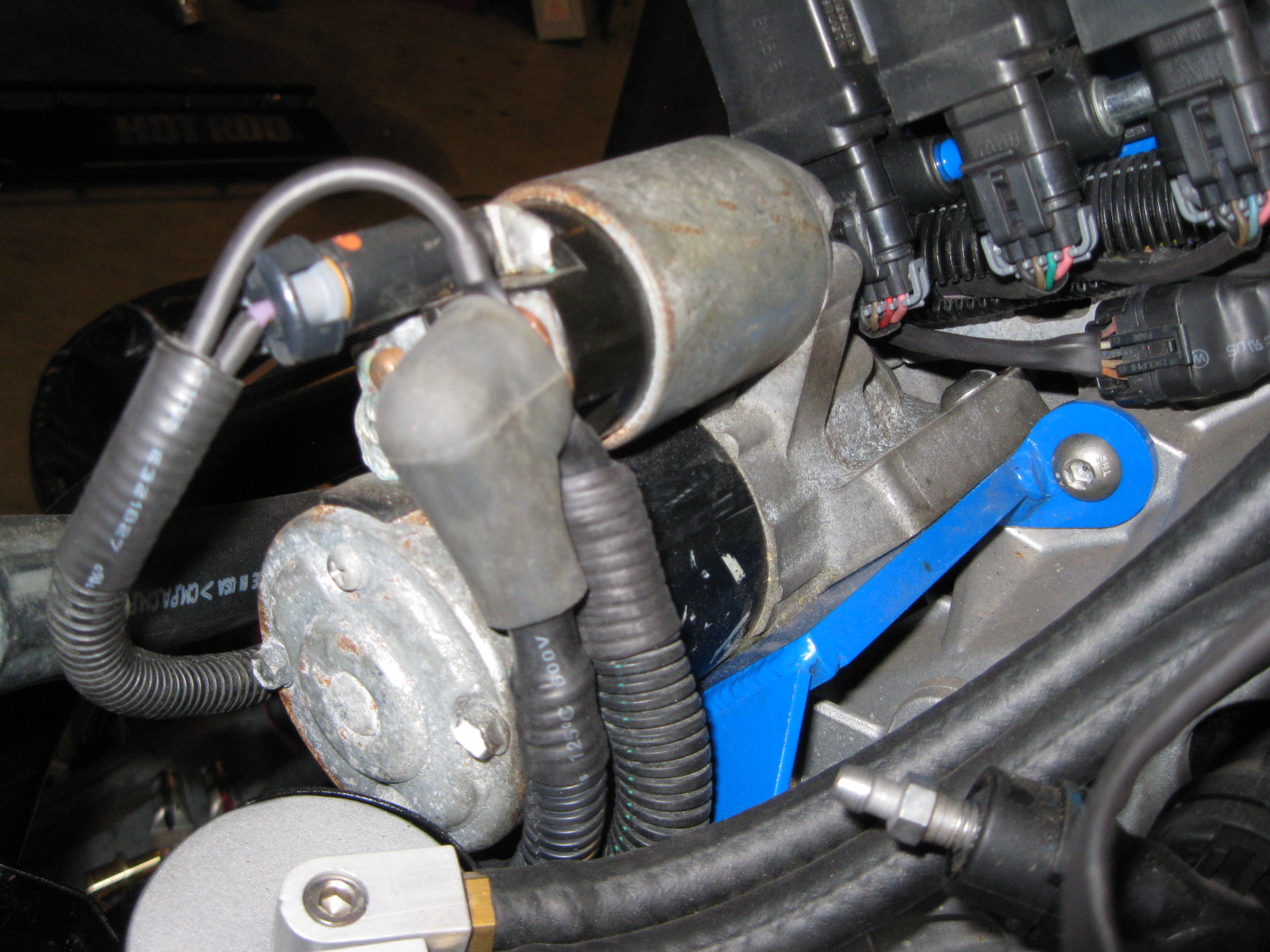
One of the last loose ends to finish up on the engine was relocating the oil level sight tube for the catch can. So I marked the holes, drilled/tapped them and now have the sight level in a visible spot:
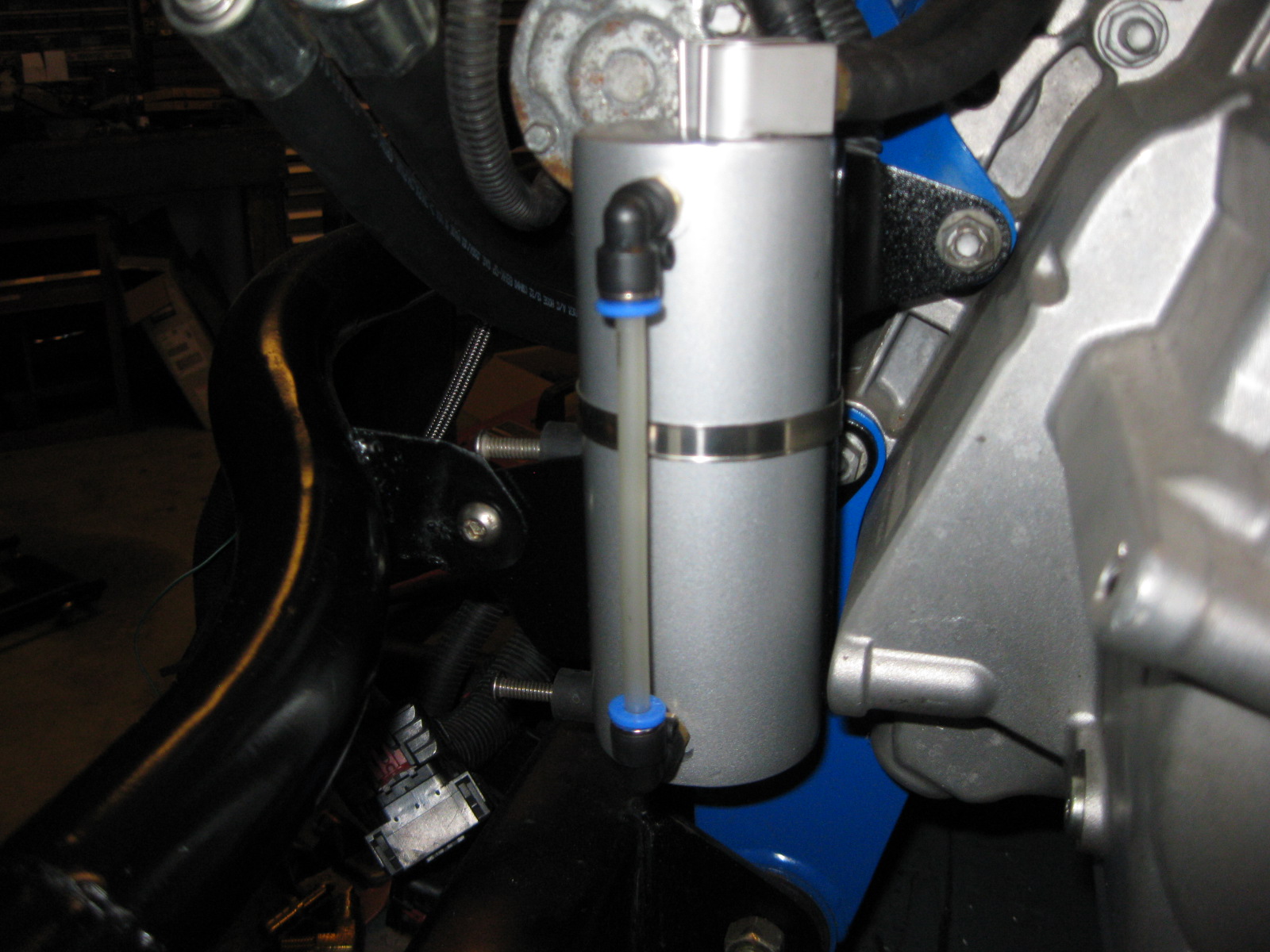
The original holes were filled with threaded caps, then the ends ground down flush (they are up against the mounting bracket:
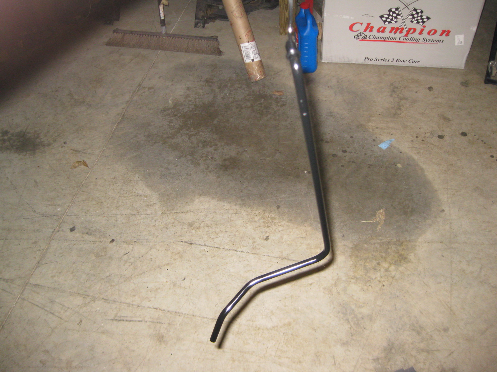
The other radiator hoses came in. These are the same as the previous one I cut up for the pipe to water pump inlet, so I figured might as well keep using the same part # to make the rest of the hoses.
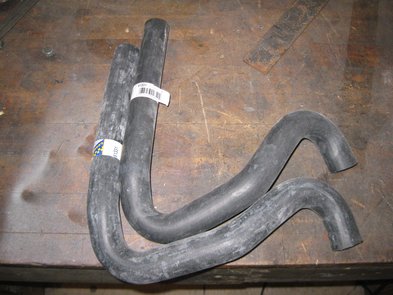
Just by cutting the hose in the proper place, I was able to use one hose for both the thermostat to pipe and lower coolant tube to pipe hoses on the passenger side:

Then doing the same on the driver side pipe to lower coolant tube:
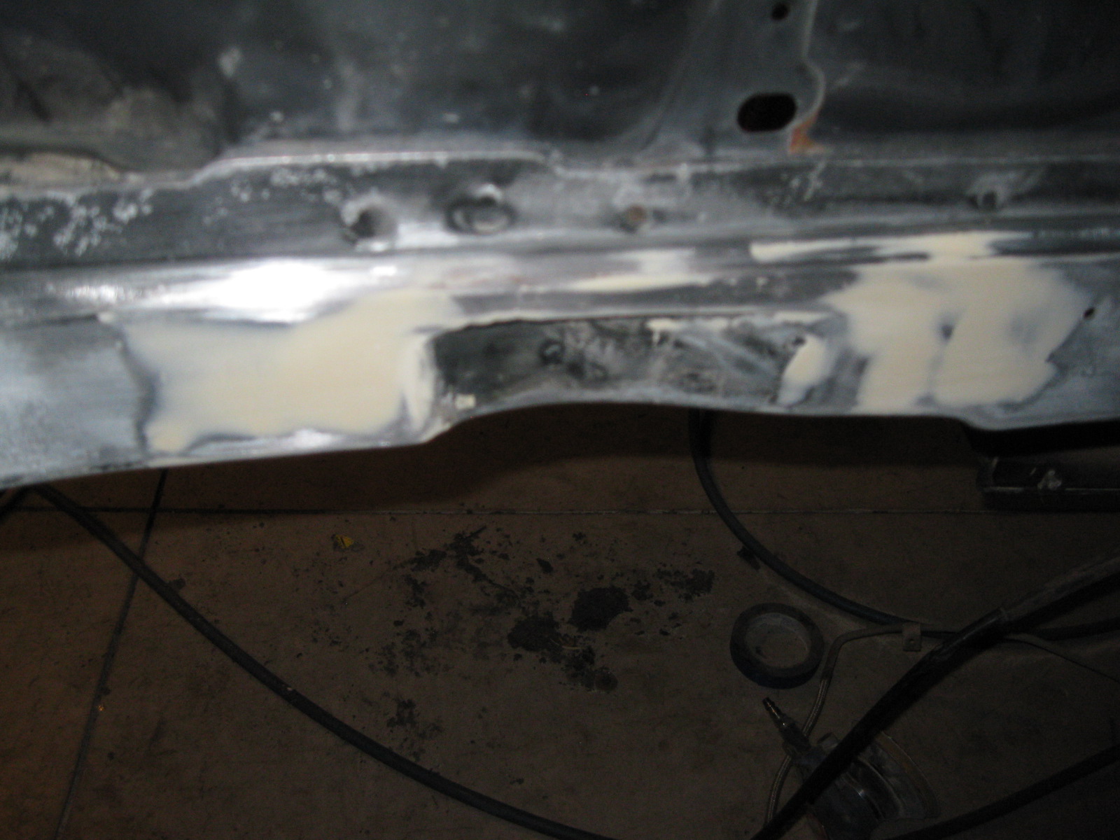
Spend some time sanding the engine bay and smoothing out the tops of the strut towers and the work I did on the driver side frame notch (moved it to the rear about 1/2"):
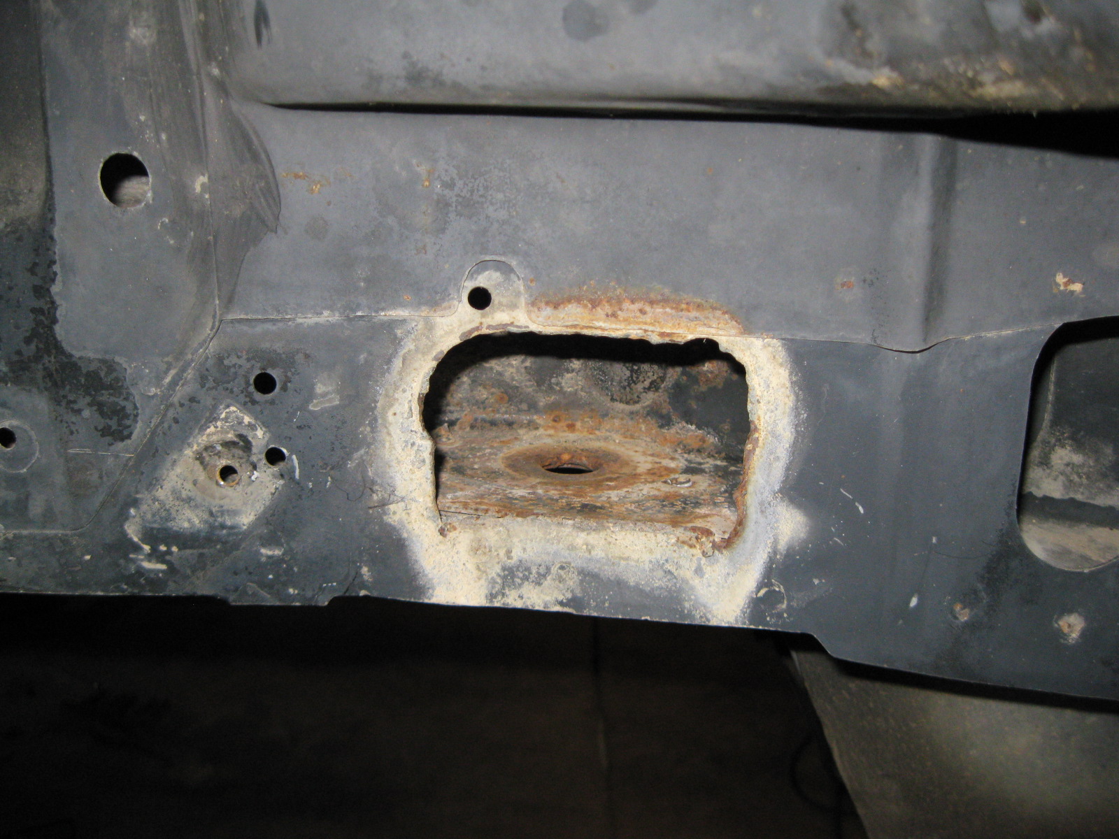
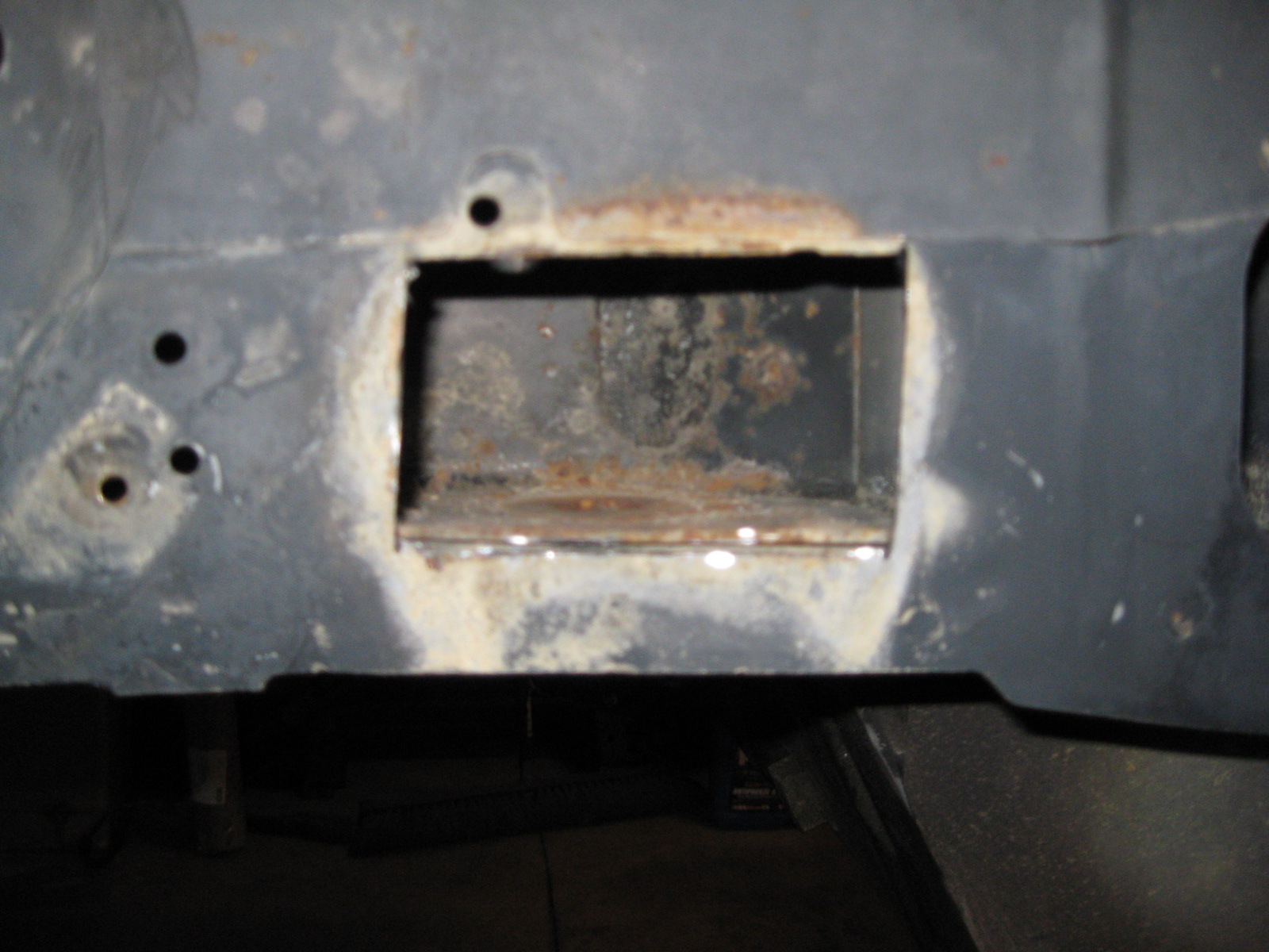
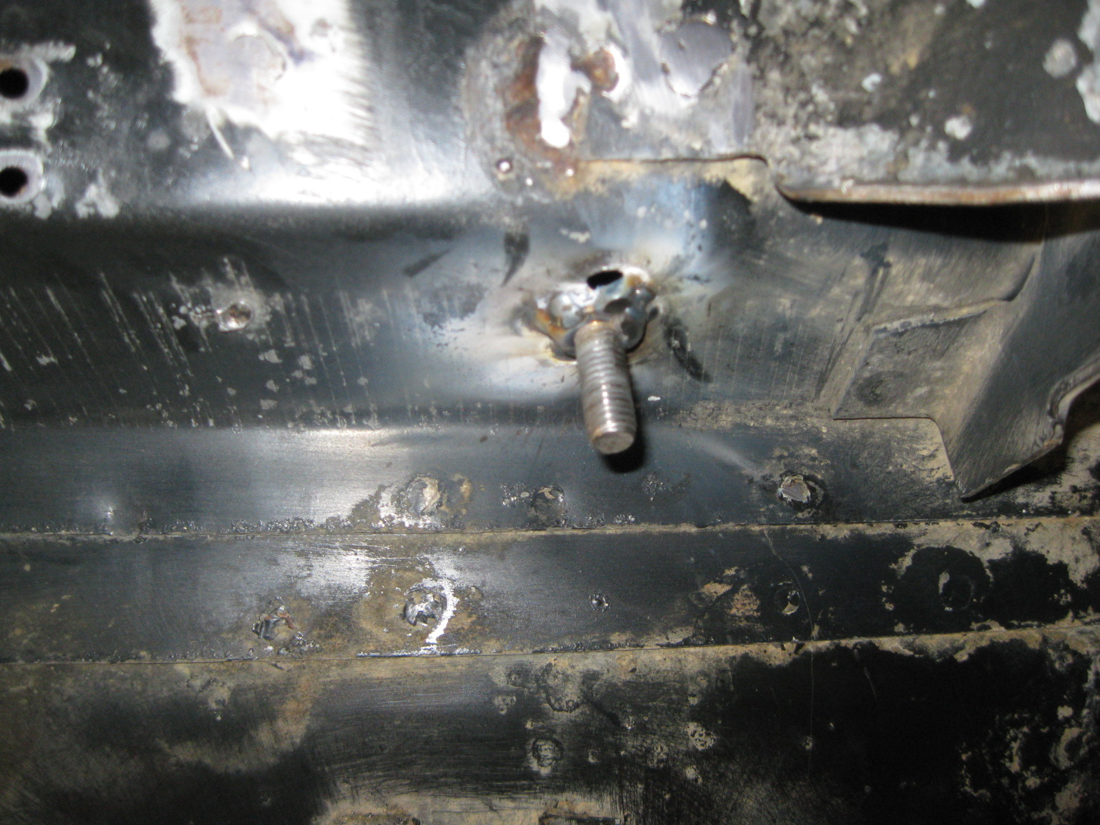
There was one place on the chassis that I really didn't like... where the previous owner or some shop cut into the side of the framerail to access the nut for the cradle bolt.
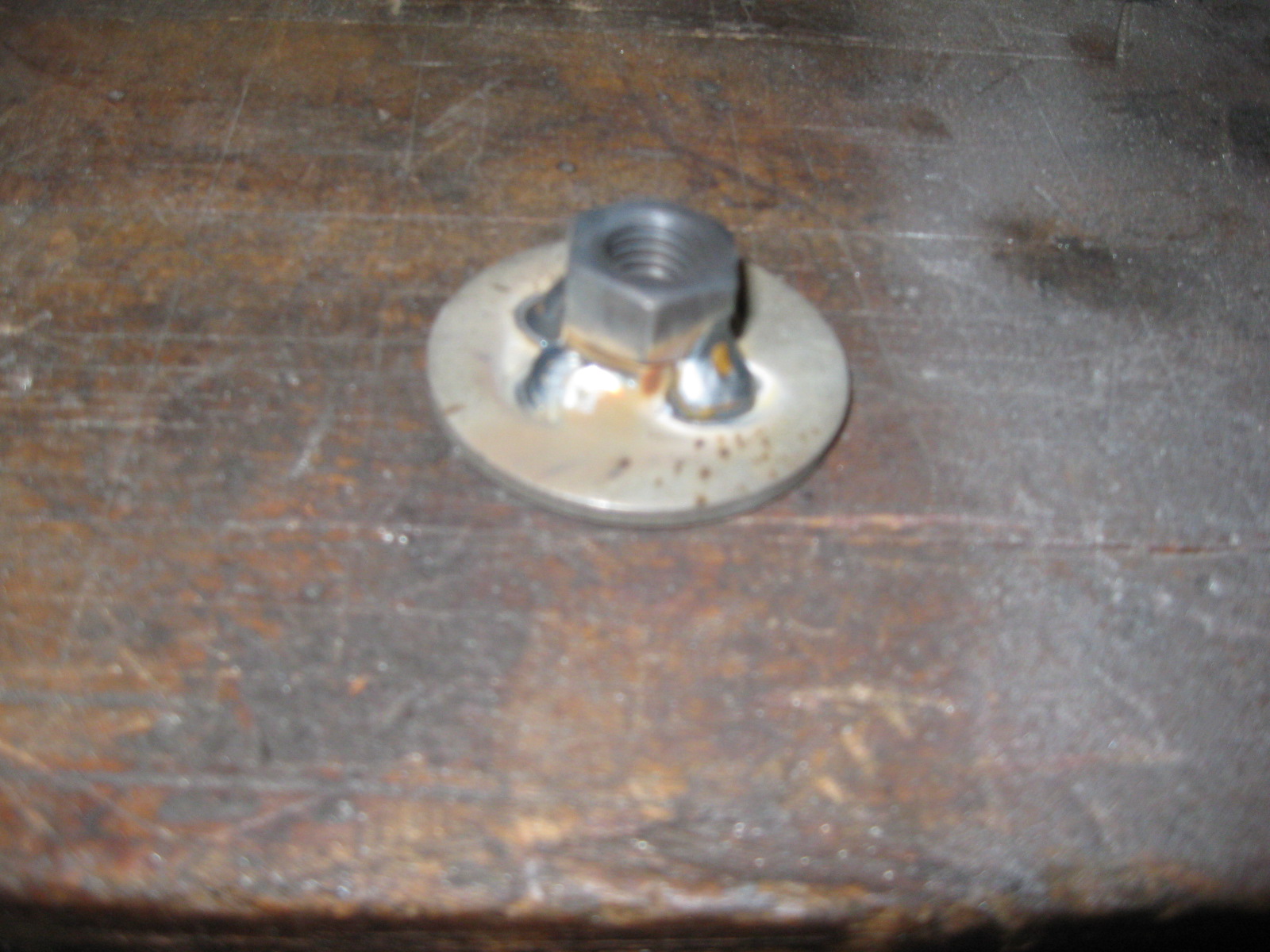
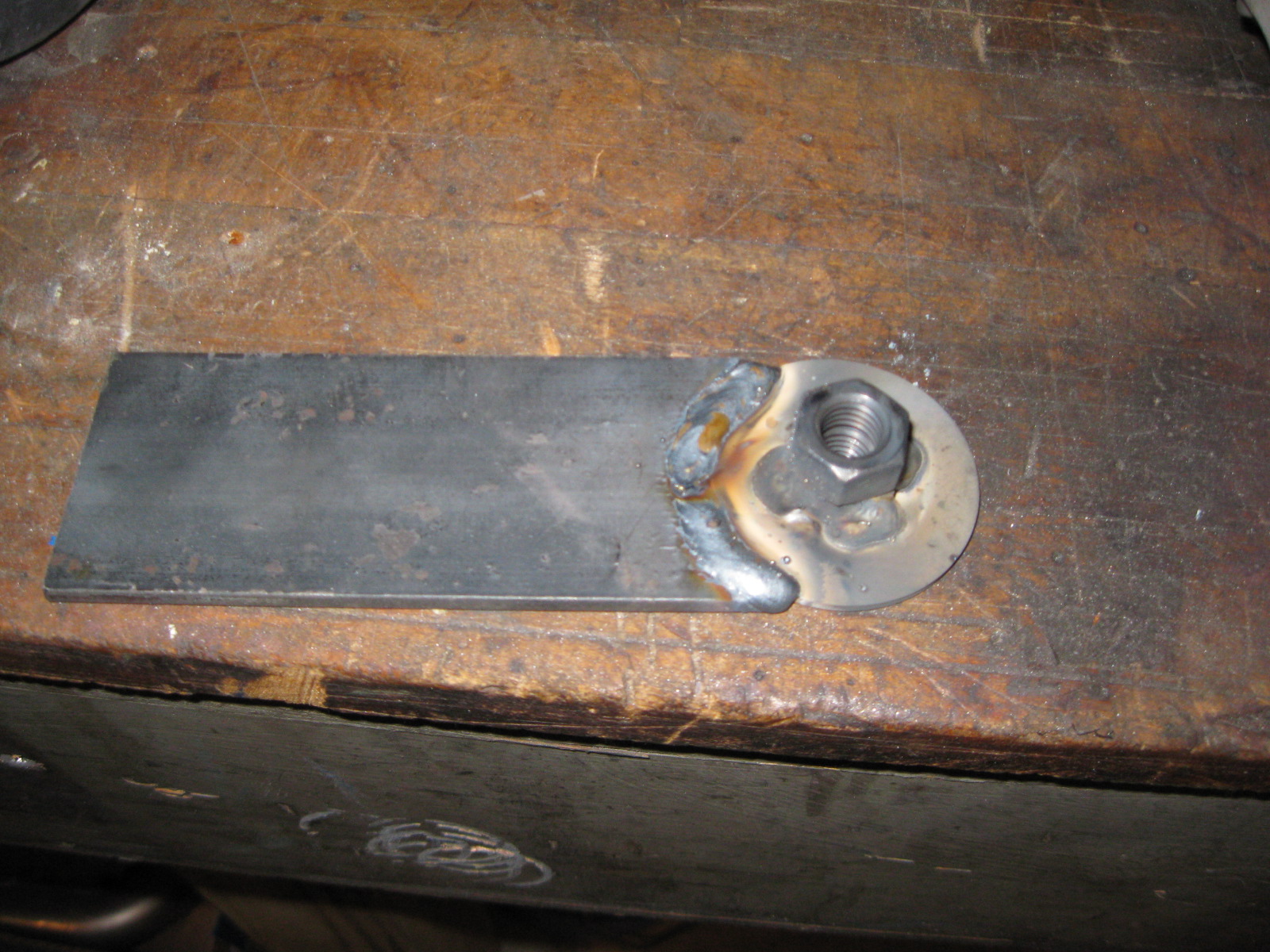
So I make a new nut assy that will sit inside the frame rail, allow some general movement side/side and front/back but not allow the nut to spin. I used some M12-1.75 nuts, pressed one into a large washer, welded the nuts to the washer and added an arm to it to keep it from spinning:

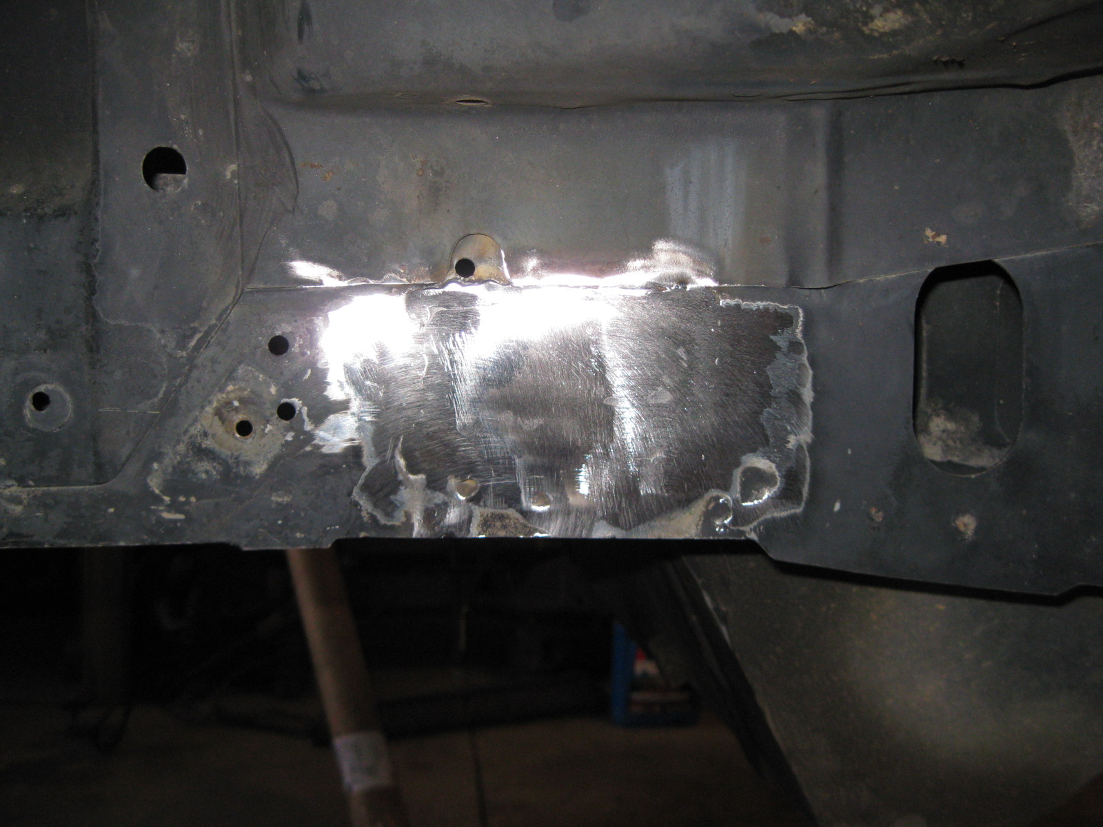
With the nut taken care of, it was time to close the hole. I figured it would be easier to make a patch panel if I cleaned up the edges of the hole, so out came the cut off disk:
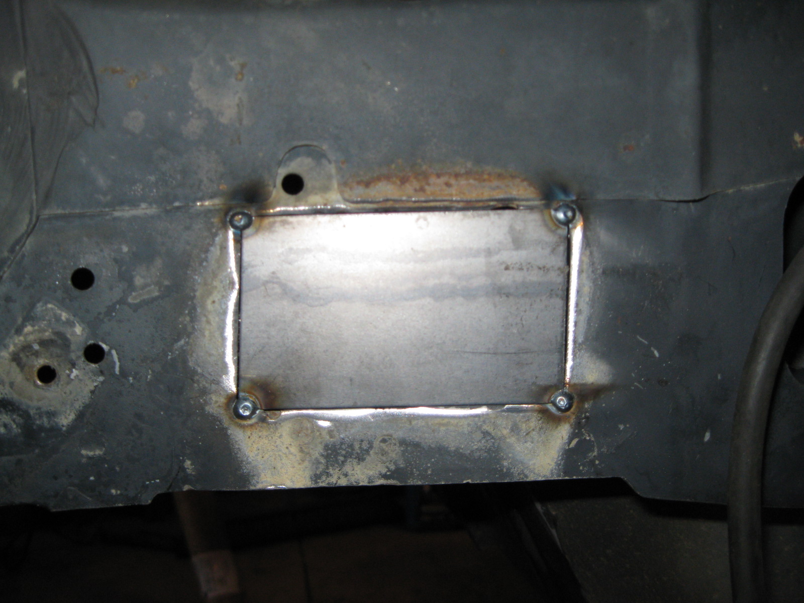
I used the cardboard from a cereal box to make a template, transferred the pattern to some 16ga, sheared out the patch panel, and tacked it in place:
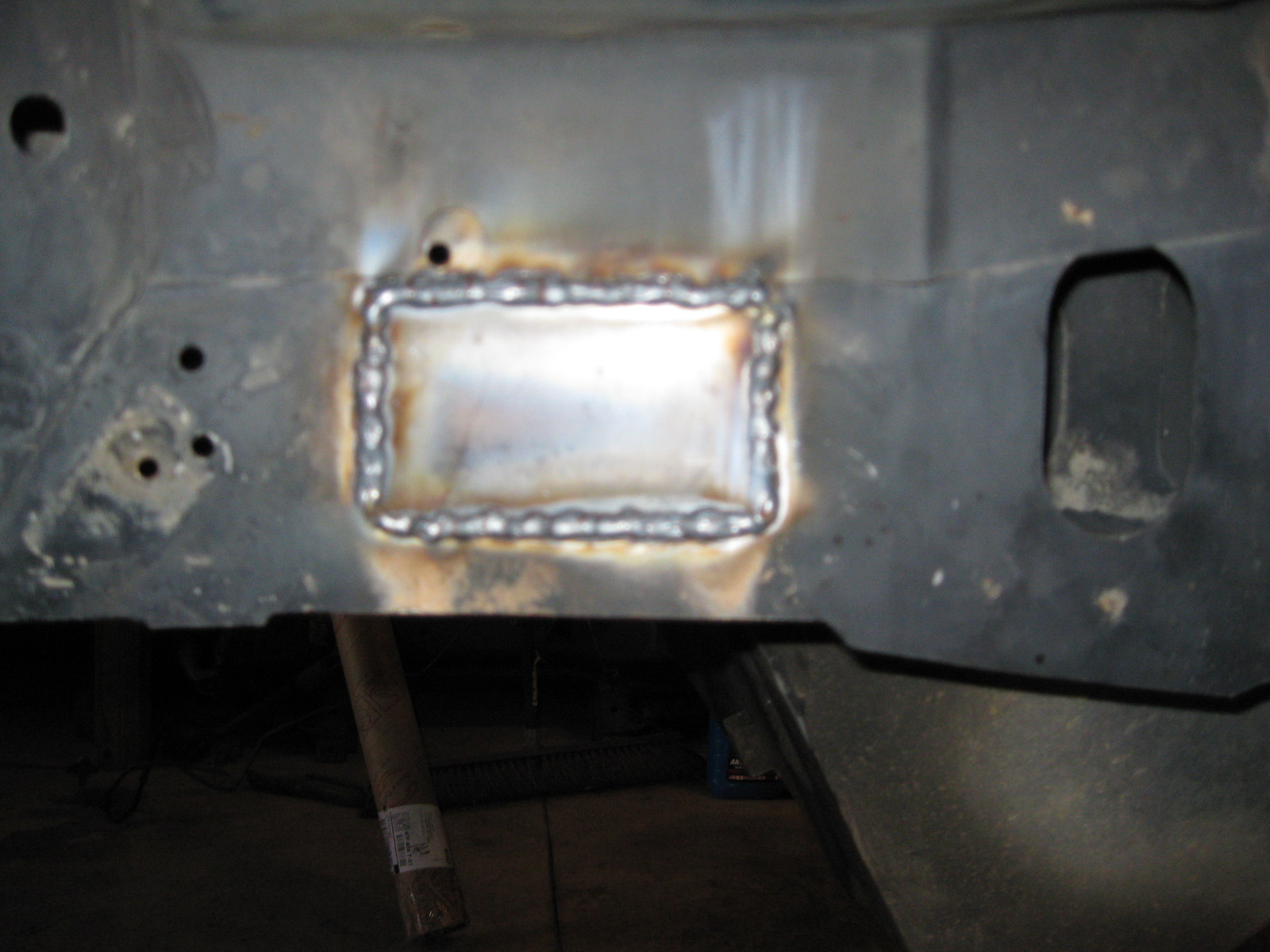
Patch fully welded:
Welds ground smooth:
The engine bay is waiting for paint, but it need to get another 5 degrees warmer in the garage first.
Once the engine bay is painted and dry, I will start to reassemble. Once the engine/tranny/cradle is in the chassis and the harness, fuel and coolant hooked up, I will see if this engine can make some noise!
The ECM and TCM are back with the stock 2007 LS4/4T65e-hd calibration loaded on them. In a week or two I will have to spend some quality time with HP tuners and do all the baseline calibration changes to this thing will actually start.
One of the last loose ends to finish up on the engine was relocating the oil level sight tube for the catch can. So I marked the holes, drilled/tapped them and now have the sight level in a visible spot:
The original holes were filled with threaded caps, then the ends ground down flush (they are up against the mounting bracket:
The other radiator hoses came in. These are the same as the previous one I cut up for the pipe to water pump inlet, so I figured might as well keep using the same part # to make the rest of the hoses.
Just by cutting the hose in the proper place, I was able to use one hose for both the thermostat to pipe and lower coolant tube to pipe hoses on the passenger side:
Then doing the same on the driver side pipe to lower coolant tube:
Spend some time sanding the engine bay and smoothing out the tops of the strut towers and the work I did on the driver side frame notch (moved it to the rear about 1/2"):
There was one place on the chassis that I really didn't like... where the previous owner or some shop cut into the side of the framerail to access the nut for the cradle bolt.
So I make a new nut assy that will sit inside the frame rail, allow some general movement side/side and front/back but not allow the nut to spin. I used some M12-1.75 nuts, pressed one into a large washer, welded the nuts to the washer and added an arm to it to keep it from spinning:
With the nut taken care of, it was time to close the hole. I figured it would be easier to make a patch panel if I cleaned up the edges of the hole, so out came the cut off disk:
I used the cardboard from a cereal box to make a template, transferred the pattern to some 16ga, sheared out the patch panel, and tacked it in place:
Patch fully welded:
Welds ground smooth:
The engine bay is waiting for paint, but it need to get another 5 degrees warmer in the garage first.
Once the engine bay is painted and dry, I will start to reassemble. Once the engine/tranny/cradle is in the chassis and the harness, fuel and coolant hooked up, I will see if this engine can make some noise!
12-30-2012, 03:16 PM
#97
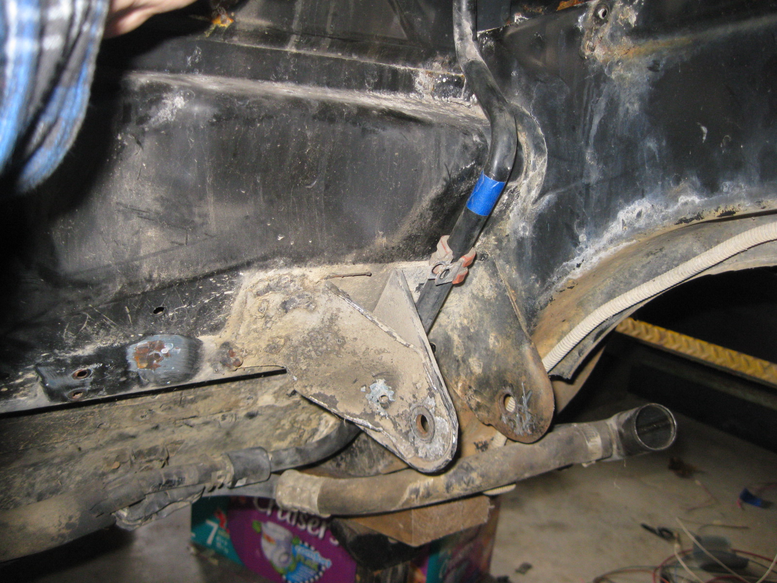
I forgot to post the pictures of the engine to chassis ground wire. Same 2ga wire used for the battery relocation and same soldered on ends. I weled a stainless steel bolt to the underside of the chassis for a solid, rust free grounding point.
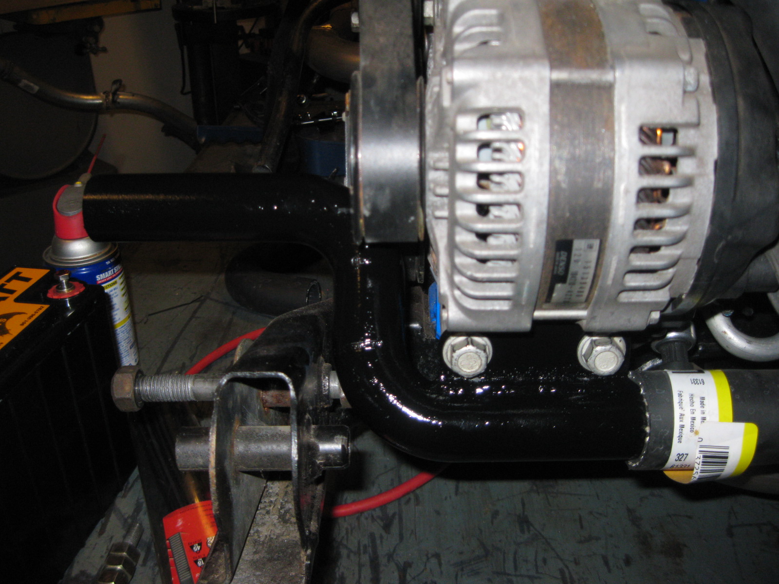
There was an unused bolt hole on the head here, so I used it:
The cable snakes down behind the hoses and over the alternator:

The ground cable from the batter will also come back to the engine, so this is just a large engine/chassis ground.
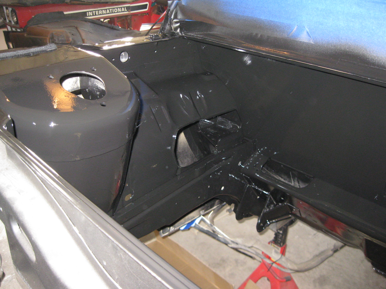
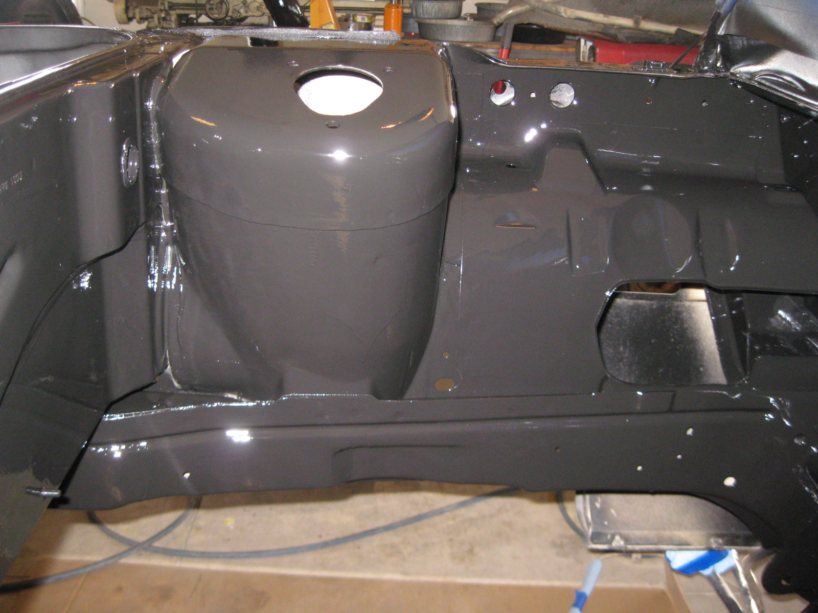
The engine bay is now painted! I painted the firewall and the backside of the smooth panel first, then once those were dry installed the smooth panel and finished painting the whole engine bay. It is a matte black finish, but is glossy in the pics because it is still wet.

There was an unused bolt hole on the head here, so I used it:
The cable snakes down behind the hoses and over the alternator:
The ground cable from the batter will also come back to the engine, so this is just a large engine/chassis ground.
The engine bay is now painted! I painted the firewall and the backside of the smooth panel first, then once those were dry installed the smooth panel and finished painting the whole engine bay. It is a matte black finish, but is glossy in the pics because it is still wet.
 01-01-2013, 05:57 PM
#99
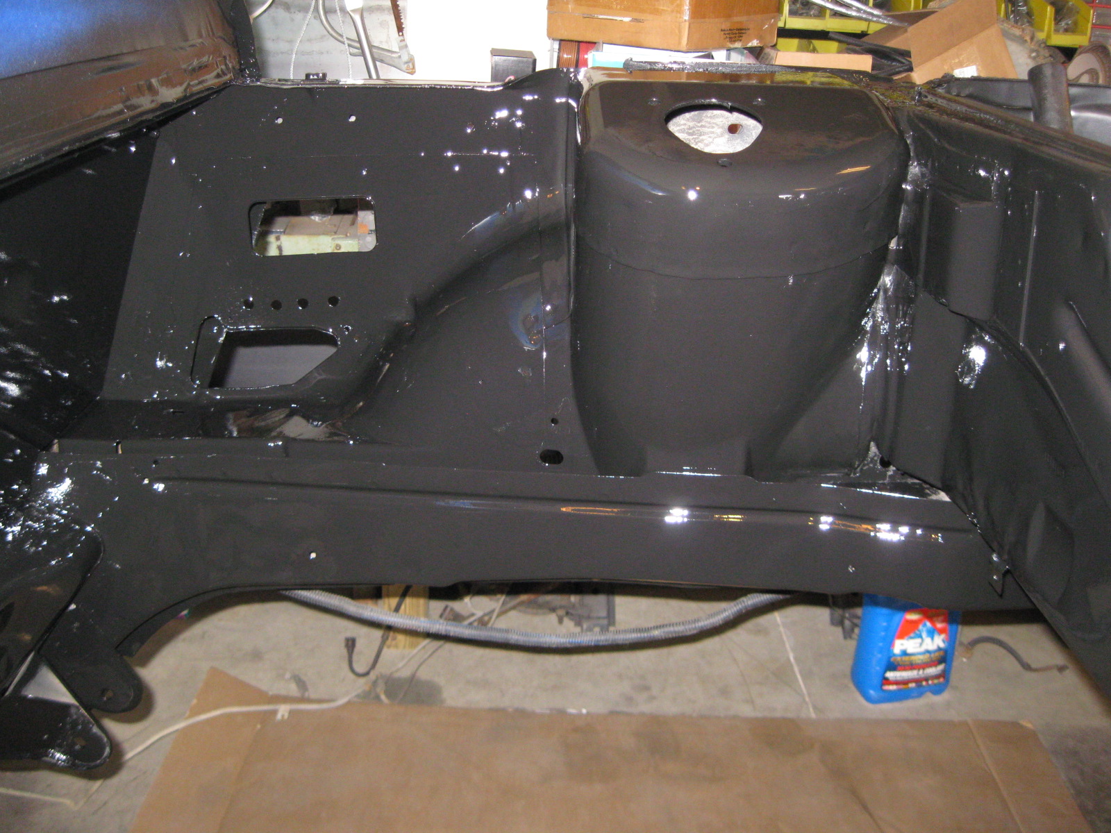
Here is a pic with the engine bay paint dry and with a low gloss finish.
I still have a little bit more touch up work on the topside of the strut towers, but it will be a week or two till it is warm enough to do more painting,
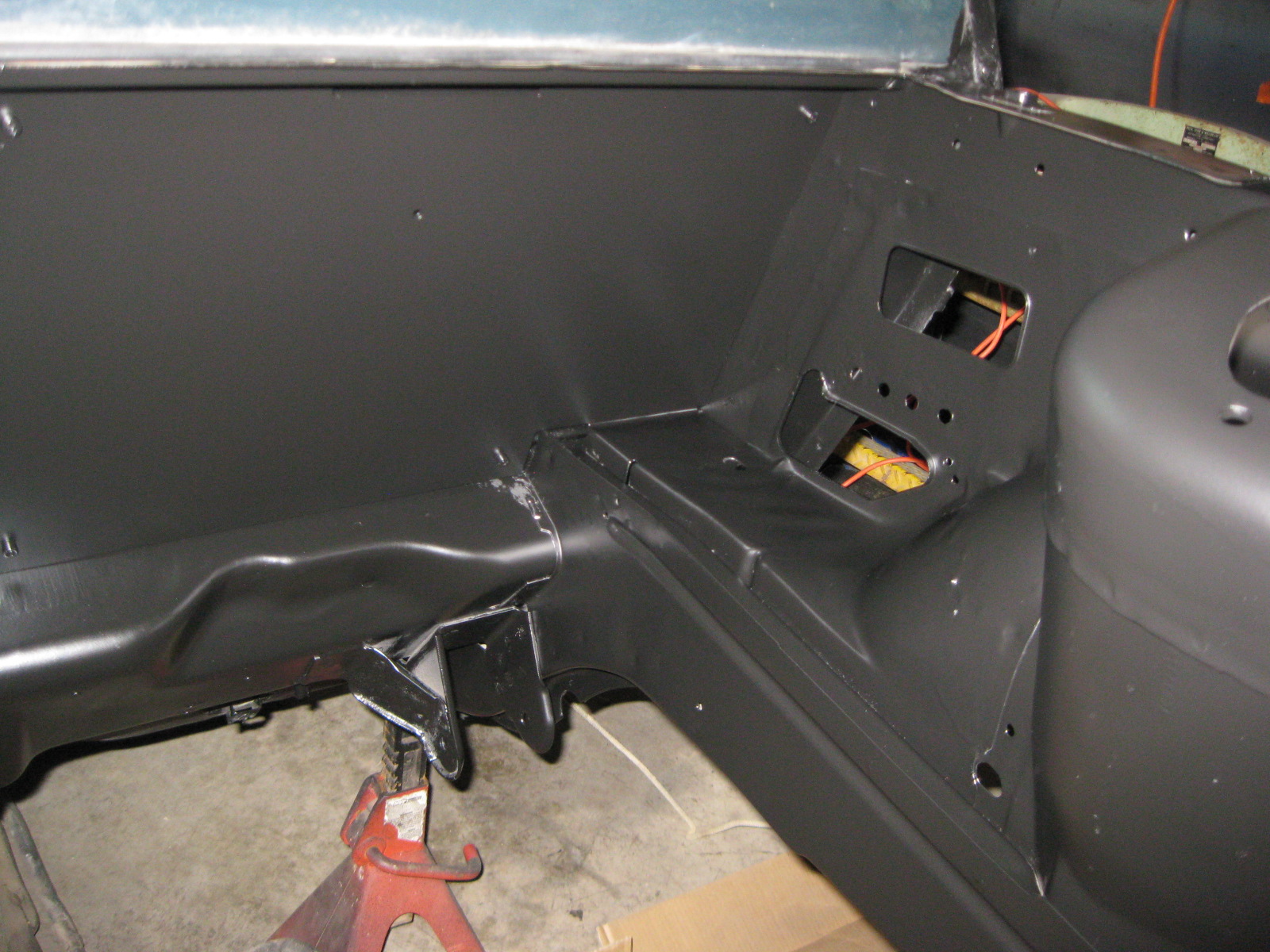
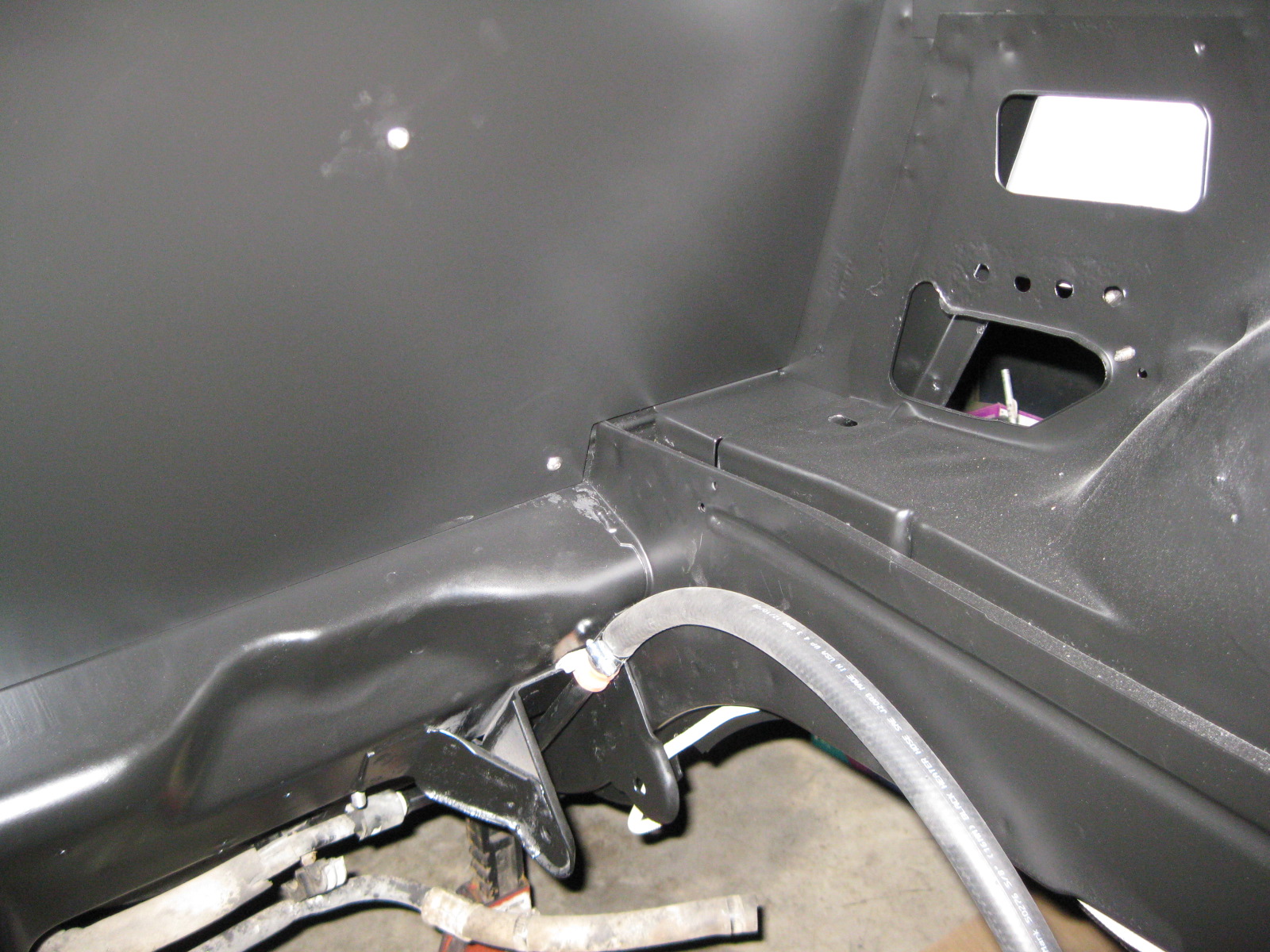
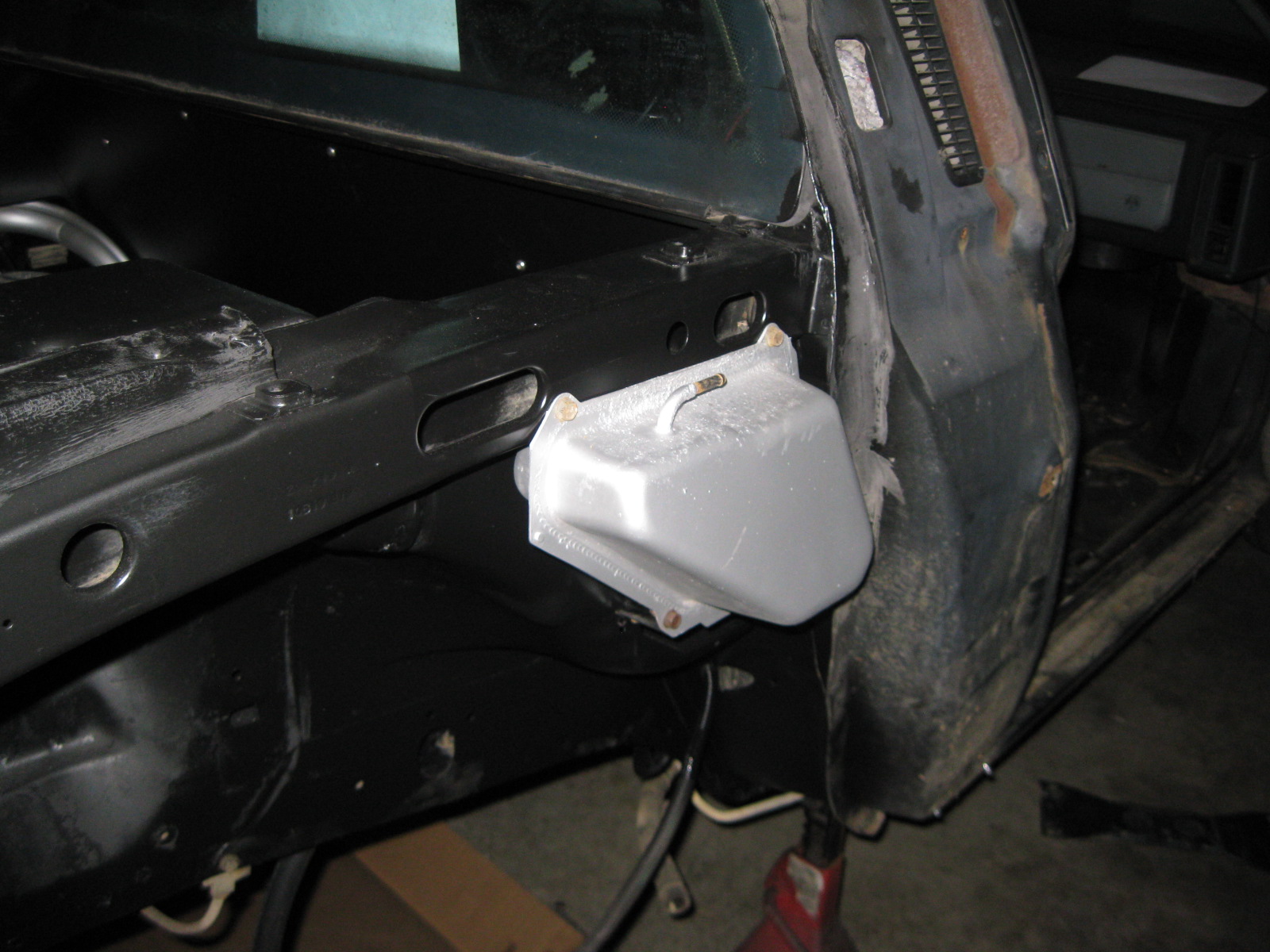
Today I swapped out the bolts in the firewall panel to stainless steel button heads, installed the fuel fill tube with a fresh coat of aluminum paint, installed the shifter cables, installed the expansion tank (with a fresh coat of aluminum paint), installed the brake and clutch lines, heater hose hard line, mounted all the hoses to the fuel tank and got it ready for installation. Here are some pics from today's work:
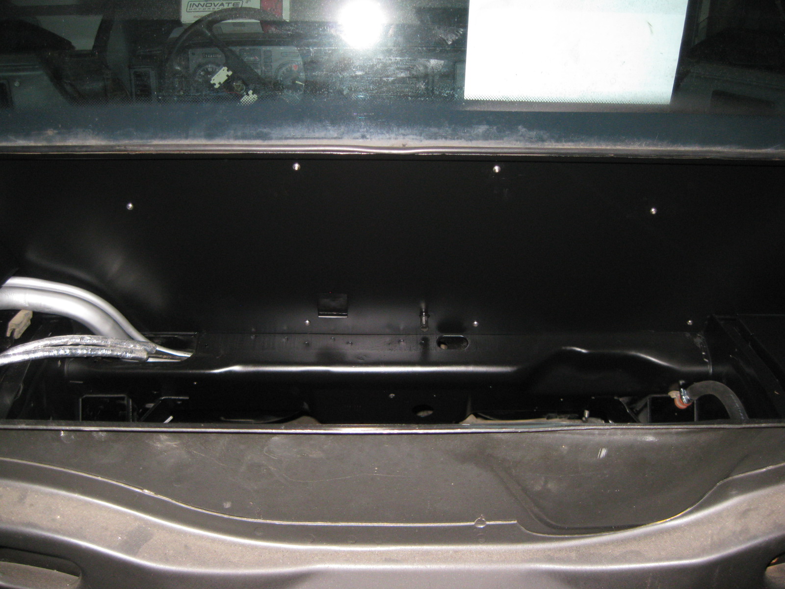


Maybe on Wednesday night I will get the fuel tank installed and the hoses cut to length and connected to the fuel filter/regulator and install the main coolant tubes (the ones on the car were kinked... but I have a kink-free set in the attic).
I still have a little bit more touch up work on the topside of the strut towers, but it will be a week or two till it is warm enough to do more painting,
Today I swapped out the bolts in the firewall panel to stainless steel button heads, installed the fuel fill tube with a fresh coat of aluminum paint, installed the shifter cables, installed the expansion tank (with a fresh coat of aluminum paint), installed the brake and clutch lines, heater hose hard line, mounted all the hoses to the fuel tank and got it ready for installation. Here are some pics from today's work:
Maybe on Wednesday night I will get the fuel tank installed and the hoses cut to length and connected to the fuel filter/regulator and install the main coolant tubes (the ones on the car were kinked... but I have a kink-free set in the attic).

