
88 Fiero Formula LS4/F40 6 speed swap
 09-29-2012, 02:23 PM
#1


I have been working on this swap off and on for nearly 2 years, but it is finally getting close to being finished.
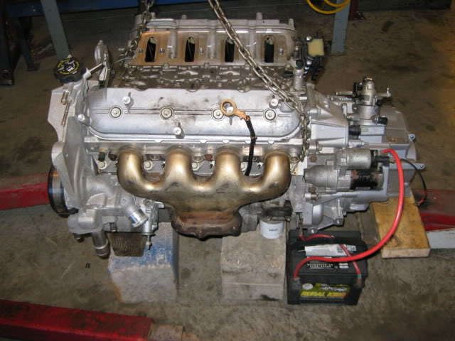
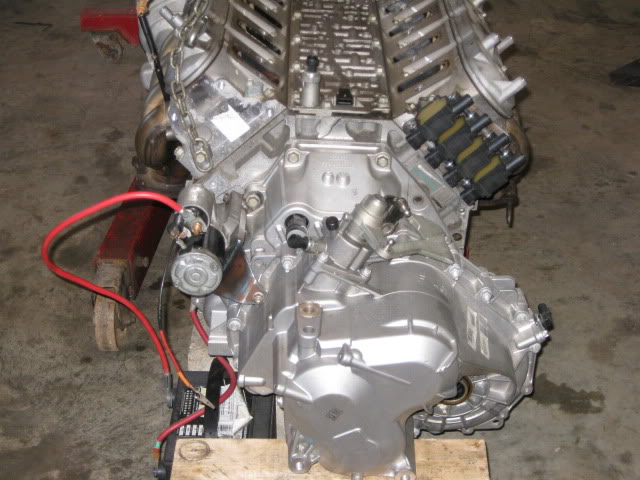
The LS4 is the bastard child of the LS(x) family with a restrictive intake and a 303hp rating, no starter provision on the block and the GM Metric bellhousing pattern (not the SBC/LS1 bolt pattern). It was designed for a transverse layout and has the shortest overall length, which is good for fitting it between the Fiero frame rails. It also bolts directly to the F40 6 speed manual transmission from the 2006+ Pontiac G6.
Since my mild SBC/getrag swap (in another 88 Fiero) put 282 hp to the wheels, I want this swap to have 50+ more whp. The more the better. So the stock 303 hp just wont get it done, and there will be several basic upgrades to raise the HP along the way.
The build plan:
*Upgrade to an 85mm MAF, LS2 DBW throttlebody, Intake, Fuel Rail and Injectors.
* Upgrade to a DoD compatible 224/232 .564/.575 @ 113 lsa
* Upgrade to LS7 hydro formed exhaust manifolds
* Custom 12# aluminum flywheel designed for the LS4/F40 application
* 10" Spec Stage 4+ clutch
* Retain DoD function... not sure if I will be able to get it to work, but going to give it a shot.
* Tuck 10 1/2" wheels under the stock body in the rear.
* 13" brake upgrade
* Several other suspension upgrades to improve handling performance.
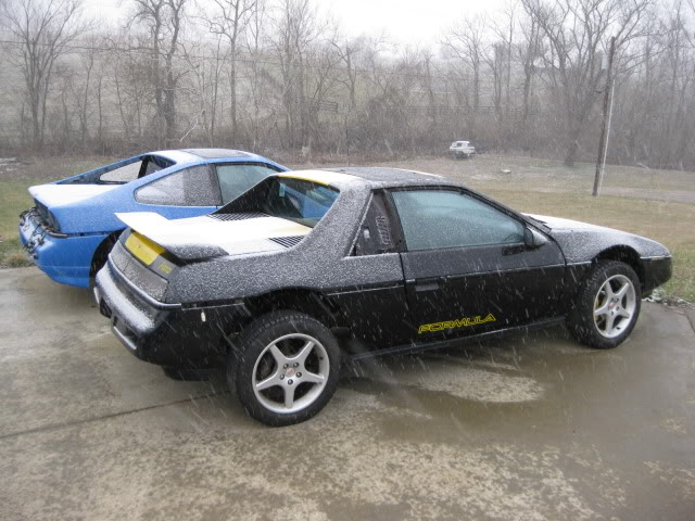
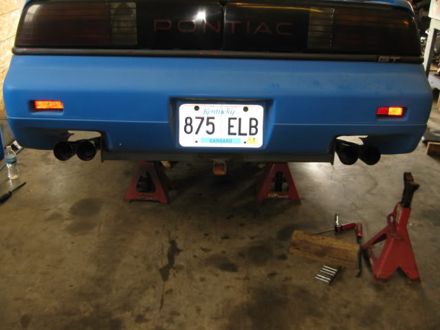
Here is the lucky recipient, but it will end up being painted to get rid of the yellow racing stripes, and will probably blue like the GT behind it (my retired SBC car).
The engine is a 2007 LS4 with 17K miles on it:
http://i152.photobucket.com/albums/s...ru/LS4/034.jpg
I will be making additional posts with lots of pictures/details of the swap, so stay tuned.
The LS4 is the bastard child of the LS(x) family with a restrictive intake and a 303hp rating, no starter provision on the block and the GM Metric bellhousing pattern (not the SBC/LS1 bolt pattern). It was designed for a transverse layout and has the shortest overall length, which is good for fitting it between the Fiero frame rails. It also bolts directly to the F40 6 speed manual transmission from the 2006+ Pontiac G6.
Since my mild SBC/getrag swap (in another 88 Fiero) put 282 hp to the wheels, I want this swap to have 50+ more whp. The more the better. So the stock 303 hp just wont get it done, and there will be several basic upgrades to raise the HP along the way.
The build plan:
*Upgrade to an 85mm MAF, LS2 DBW throttlebody, Intake, Fuel Rail and Injectors.
* Upgrade to a DoD compatible 224/232 .564/.575 @ 113 lsa
* Upgrade to LS7 hydro formed exhaust manifolds
* Custom 12# aluminum flywheel designed for the LS4/F40 application
* 10" Spec Stage 4+ clutch
* Retain DoD function... not sure if I will be able to get it to work, but going to give it a shot.
* Tuck 10 1/2" wheels under the stock body in the rear.
* 13" brake upgrade
* Several other suspension upgrades to improve handling performance.
Here is the lucky recipient, but it will end up being painted to get rid of the yellow racing stripes, and will probably blue like the GT behind it (my retired SBC car).
The engine is a 2007 LS4 with 17K miles on it:
http://i152.photobucket.com/albums/s...ru/LS4/034.jpg
I will be making additional posts with lots of pictures/details of the swap, so stay tuned.

The following users liked this post:
LS4eva (09-17-2020)
09-29-2012, 02:28 PM
#2
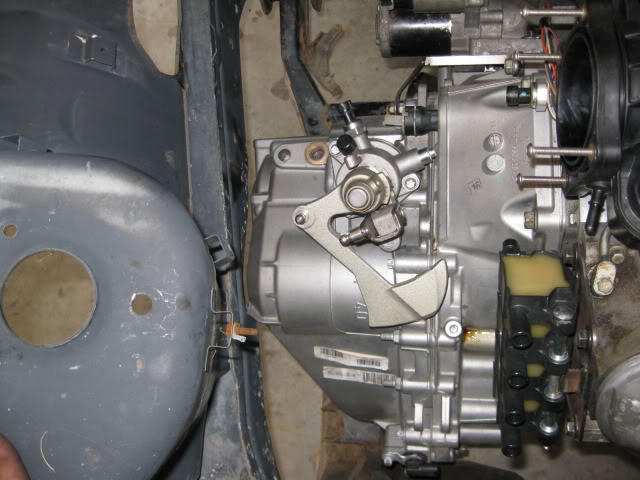
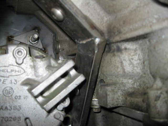
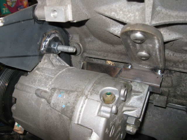
The literal go/no-go of this swap was to find a starter solution.
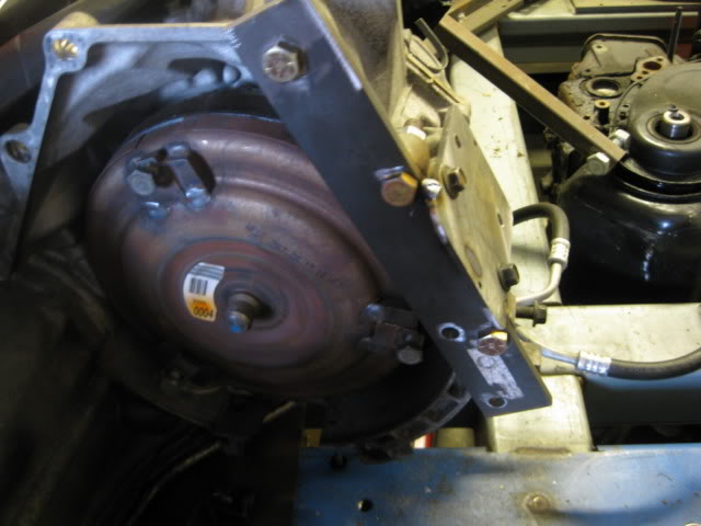
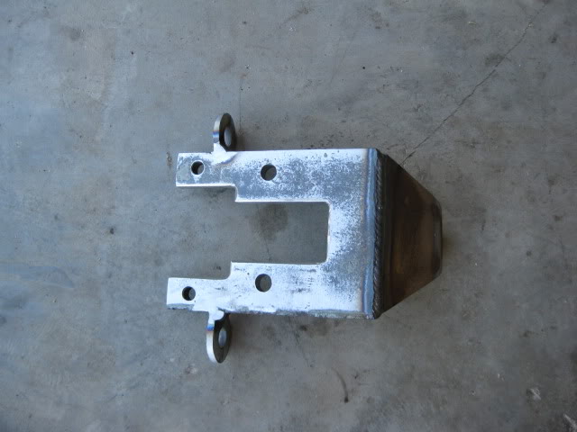
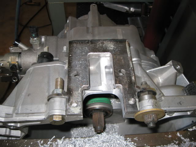
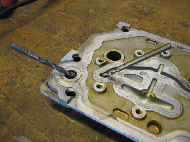
Since the LS4 never had a starter provision on the engine side, the F40 needed a starter provision on the tranny side. Nothing like cutting a hole in a brand new transmission� but it needed to be done. Using the 4T65E-HD, a fixture was mocked up so the starter pad shape and location could be transferred to the F40. Then it was a matter of removing enough aluminum on the F40 to allow the new starter mount to be properly positioned. End result is a bolt on starter mount for the F40 transmission that will spin the LS4.
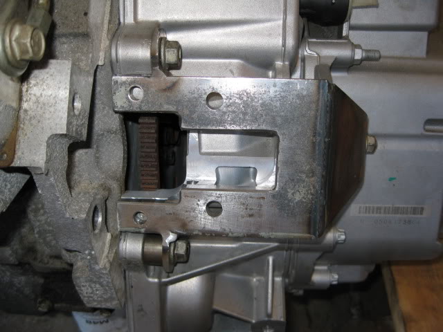
Fire In The Hole!!!
[YOUTUBE]http://www.youtube.com/watch?v=W1S3xkFRL6U[/YOUTUBE]
Since the LS4 never had a starter provision on the engine side, the F40 needed a starter provision on the tranny side. Nothing like cutting a hole in a brand new transmission� but it needed to be done. Using the 4T65E-HD, a fixture was mocked up so the starter pad shape and location could be transferred to the F40. Then it was a matter of removing enough aluminum on the F40 to allow the new starter mount to be properly positioned. End result is a bolt on starter mount for the F40 transmission that will spin the LS4.
Fire In The Hole!!!
[YOUTUBE]http://www.youtube.com/watch?v=W1S3xkFRL6U[/YOUTUBE]
The following 2 users liked this post by fieroguru:
LS4eva (09-17-2020), NewOrleansLT1 (06-27-2023)
09-29-2012, 02:46 PM
#3
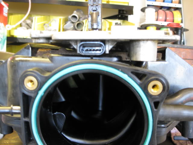
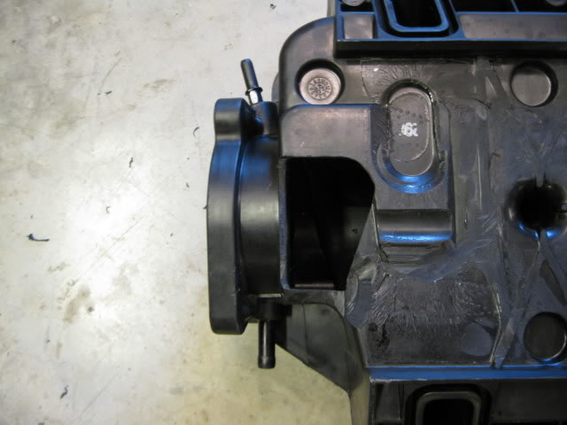
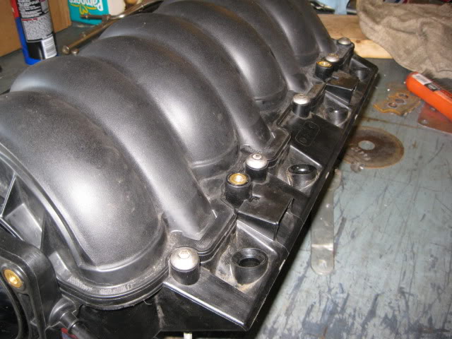
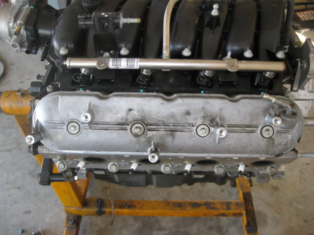
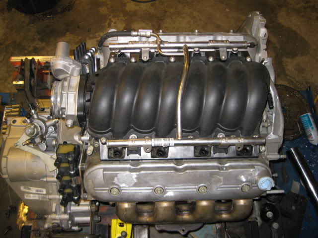
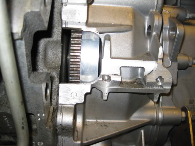
Besides being restrictive, the LS4 intake is just plain ugly and this swap needs to look good without any engine covers� Now while the LS2 intake isn�t as good as the LS6 one, it has very clean lines for use without any covers. LS4 intake on the left.
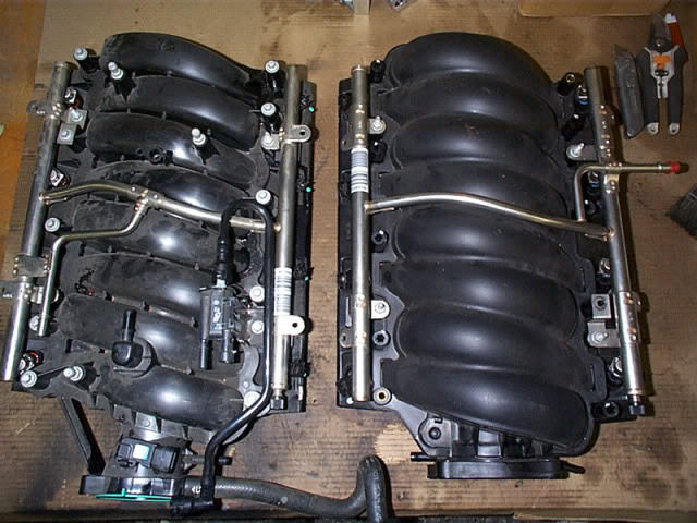
The problem is the LS2 intake will not fit the stock LS4 DoD valley cover without major clearance work (remember the intake is installed with the throttle body over the transmission for this installation) . Even with the OPSU boss cut down about 1/2" in this picture, you can see the valley cover needs to come down another 3/8" to be able to fit... this is going to take some work.
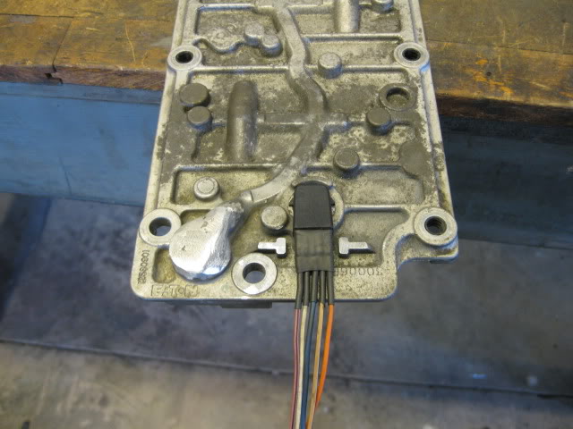
First thing under the knife was the connector.
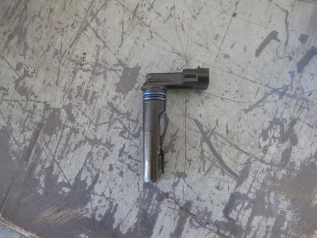
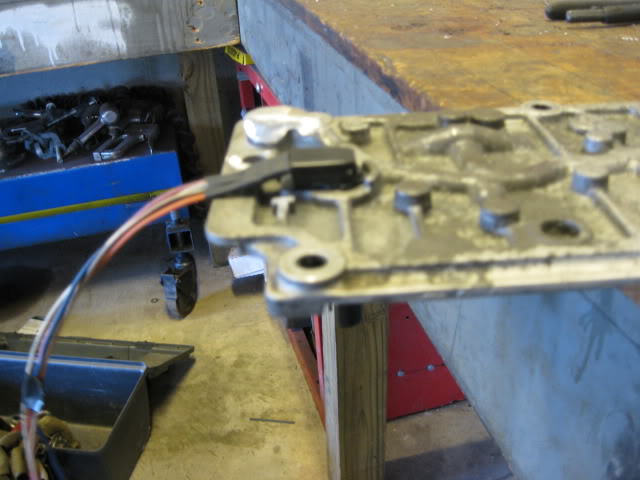
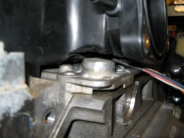
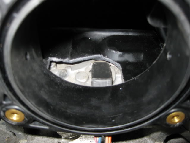
Now back to the OPSU - it will be relocated entirely. I had already cut it down about 1/2" and cut it down another 3/8" to expose the oil passage while still leaving material to drill a new oil passage.
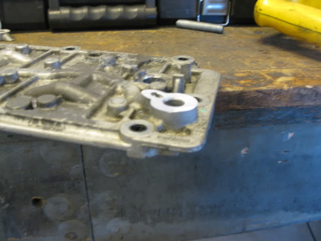
New oil passage:
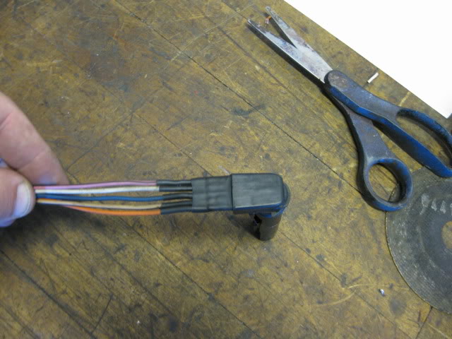
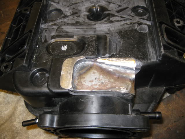
Then the top side of the OPSU boss was welded up to close up the passages. Here is a finished pic of the welded OPSU and the modified connector:
Sadly, the LS2 intake still isn't going to accept installation without modifying the intake. Lower ribs flattened and the area of the connector and OPSU was cut open (this also give me room for the vent upgrade):
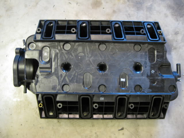
But now it can be installed w/o interference:
Patch panel fabricated to seal the hole:
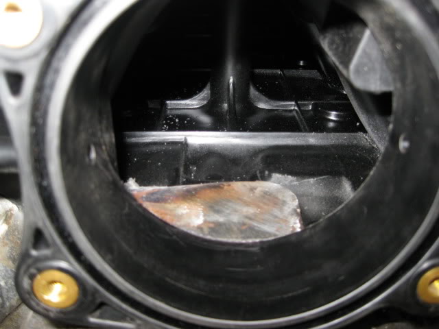
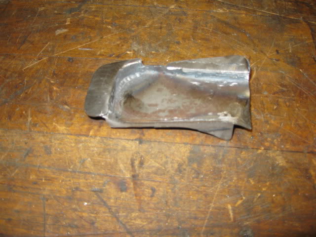
This patch panel was glued in place inside and out.
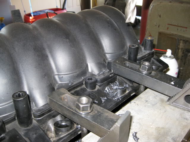
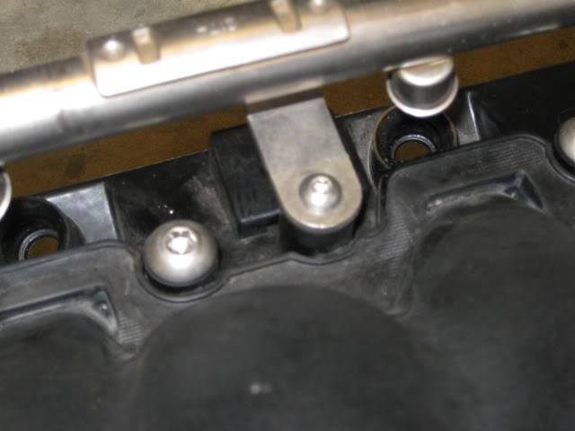
Just because I thought they would look better, I cut the intake manifold bold bosses down about 1�
I have a sickness for stainless steel button heads and even at this shorter length, they just do not exist in the proper length/thread... so I made some using some other metric stainless steel button heads. Drilled the center, cut the OEM bolts the proper length, pressed them into the bottom of the button heads, weld then together, grind off the excess...
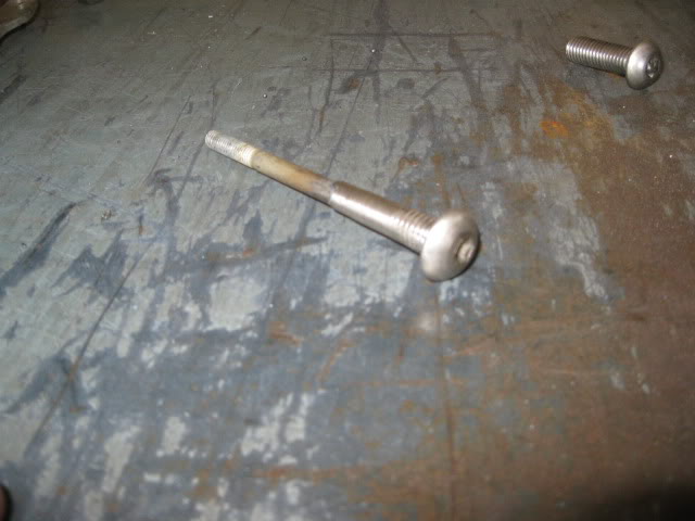
Even have button heads for the fuel rail and throttle body:
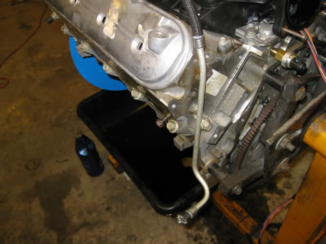
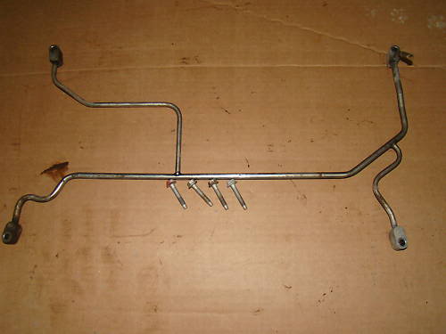
The last intake manifold modification was to bend the stock LS2 fuel rail so the fuel line will not cross over the valve cover (like the stock LS4) and then bent the original LS4 fuel line to go down the end of the head and exit down low away from the exhaust.
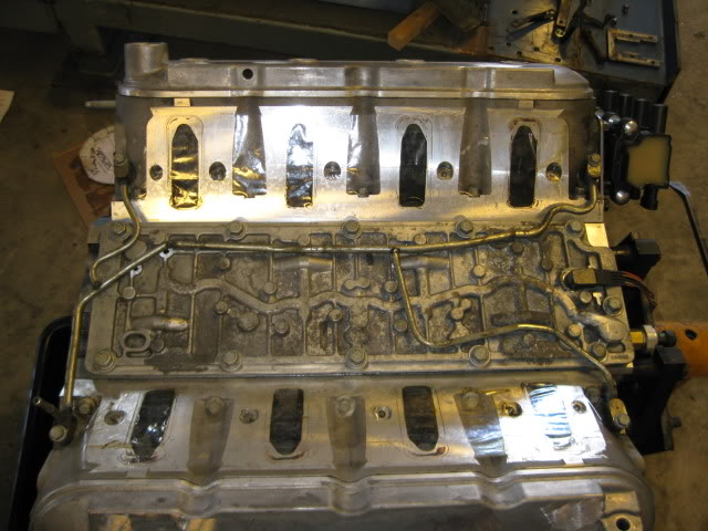
In this picture you can see where the OPSU was relocated - drilled/tapped the oil passage below the valley cover:
One last upgrade while the intake is off�
I plan to wail on this engine once installed and it might see some NO2 at some point, so I went ahead and installed the 4 corner vent setup from a 6.0L truck just to ensure cylinders 7&8 have the best chance for equal cooling.
It took some slight bending of the lines to route them around all the raised bosses and oil passages and I bent the exit tube to be vertical so it clears the intake. 2 bolt bosses for the DoD stuff under the cover needed cut down, but not far enough to touch the bolts. Some RTV should seal them back up. The bottom corner of the LS2 intake (the triangle part that rests between the heads and the valled cover) needed about 1/2" trimmed from it at the corner to clear the tube in the upper right hand corner of the picture. But now it fits!
The problem is the LS2 intake will not fit the stock LS4 DoD valley cover without major clearance work (remember the intake is installed with the throttle body over the transmission for this installation) . Even with the OPSU boss cut down about 1/2" in this picture, you can see the valley cover needs to come down another 3/8" to be able to fit... this is going to take some work.
First thing under the knife was the connector.
Now back to the OPSU - it will be relocated entirely. I had already cut it down about 1/2" and cut it down another 3/8" to expose the oil passage while still leaving material to drill a new oil passage.
New oil passage:
Then the top side of the OPSU boss was welded up to close up the passages. Here is a finished pic of the welded OPSU and the modified connector:
Sadly, the LS2 intake still isn't going to accept installation without modifying the intake. Lower ribs flattened and the area of the connector and OPSU was cut open (this also give me room for the vent upgrade):
But now it can be installed w/o interference:
Patch panel fabricated to seal the hole:
This patch panel was glued in place inside and out.
Just because I thought they would look better, I cut the intake manifold bold bosses down about 1�
I have a sickness for stainless steel button heads and even at this shorter length, they just do not exist in the proper length/thread... so I made some using some other metric stainless steel button heads. Drilled the center, cut the OEM bolts the proper length, pressed them into the bottom of the button heads, weld then together, grind off the excess...
Even have button heads for the fuel rail and throttle body:
The last intake manifold modification was to bend the stock LS2 fuel rail so the fuel line will not cross over the valve cover (like the stock LS4) and then bent the original LS4 fuel line to go down the end of the head and exit down low away from the exhaust.
In this picture you can see where the OPSU was relocated - drilled/tapped the oil passage below the valley cover:
One last upgrade while the intake is off�
I plan to wail on this engine once installed and it might see some NO2 at some point, so I went ahead and installed the 4 corner vent setup from a 6.0L truck just to ensure cylinders 7&8 have the best chance for equal cooling.
It took some slight bending of the lines to route them around all the raised bosses and oil passages and I bent the exit tube to be vertical so it clears the intake. 2 bolt bosses for the DoD stuff under the cover needed cut down, but not far enough to touch the bolts. Some RTV should seal them back up. The bottom corner of the LS2 intake (the triangle part that rests between the heads and the valled cover) needed about 1/2" trimmed from it at the corner to clear the tube in the upper right hand corner of the picture. But now it fits!
The following users liked this post:
LS4eva (09-17-2020)
09-29-2012, 02:59 PM
#4
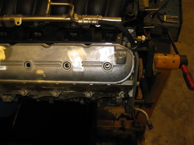
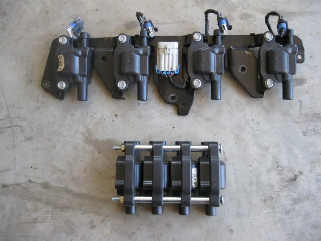
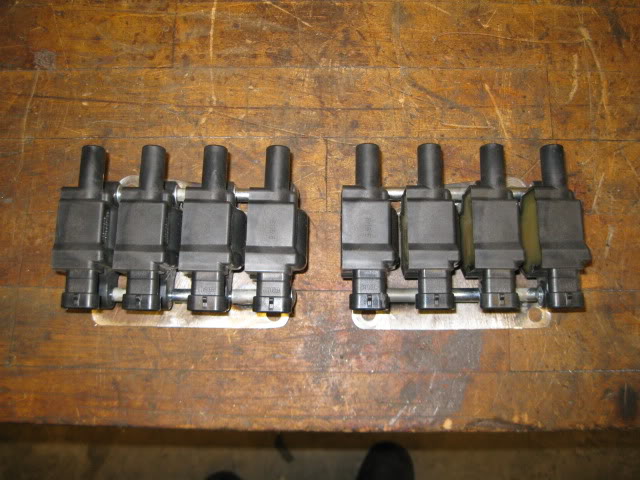
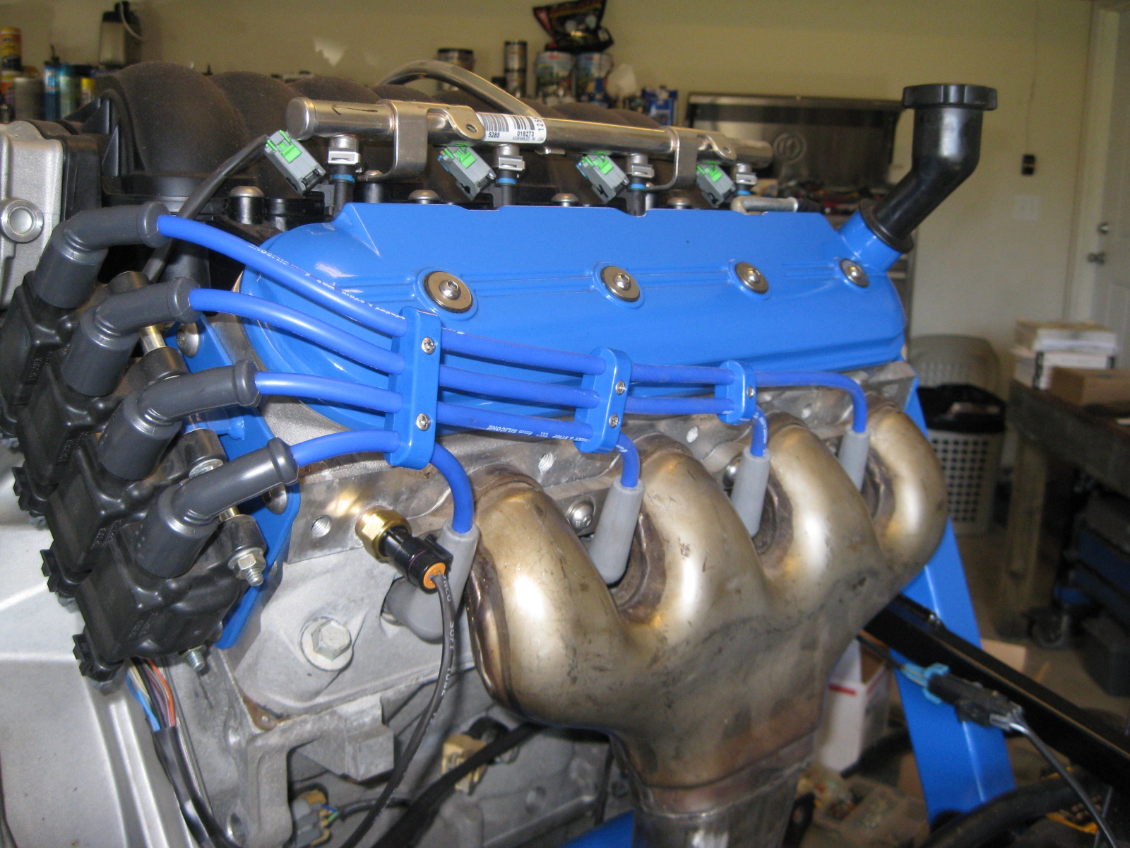
The other significant beautification modification was to do something with the unsightly coil arrangement and collection of wires over the valve covers (valve covers are to be seen, not covered). After some dis-assembly and brainstorming, the LS4 coils fit together quite nicely when mounted with some off the shelf spacers from Lowes:
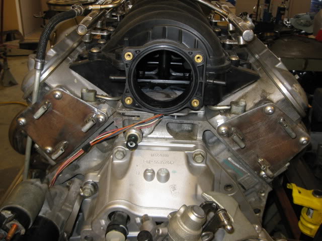
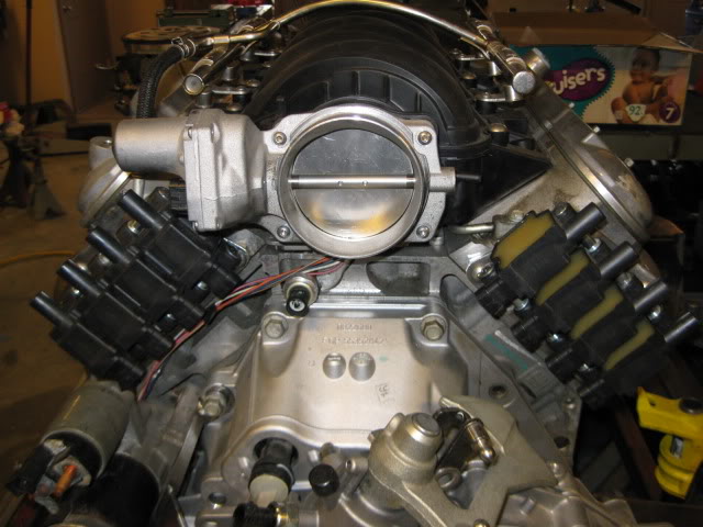
Then it was a matter of determining where on the engine this more compact coil pack could be positioned. Had I used headers, along the oil pan would have made them disappear all together, but since the LS7 manifolds do not have room for the plug wires to come from underneath, I settled on this area:
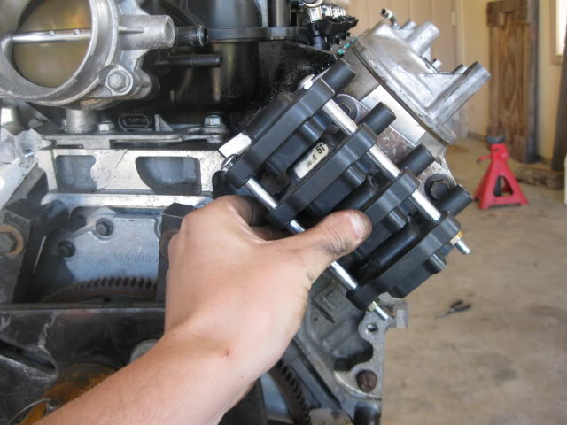
Some 1/8� scrap plate and a little fabrication and I had these:
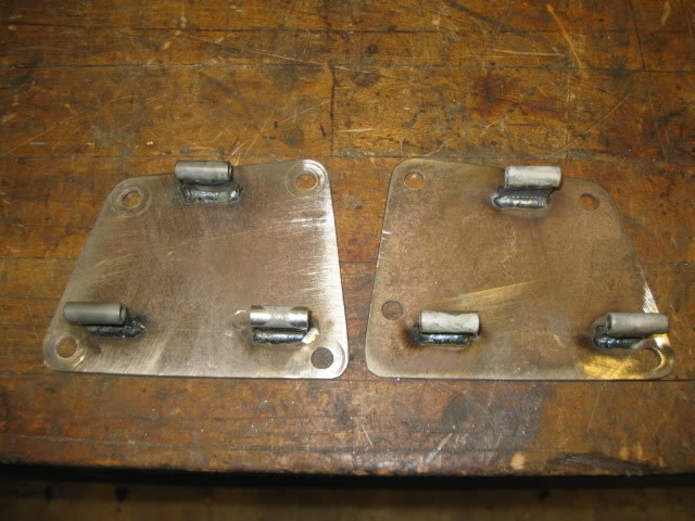
The really nice part about the coils being in this location is all the harness connectors point down to the bellhousing area, so the harness will be mostly hidden from view.
Once the coils were off the valve covers, it was time to cut down the bosses, weld up the holes and smooth everything to get a nice clean look.
Here is good inspirational shot of the intake, coil and valve cover work so far. The stock LS4 fuel line will pass behind the front coil pack and disappear from view. The only wiring that will need to be on top of the intake will be for the injectors and those will be ran under the fuel rails out of sight as well.
Then it was a matter of determining where on the engine this more compact coil pack could be positioned. Had I used headers, along the oil pan would have made them disappear all together, but since the LS7 manifolds do not have room for the plug wires to come from underneath, I settled on this area:
Some 1/8� scrap plate and a little fabrication and I had these:
The really nice part about the coils being in this location is all the harness connectors point down to the bellhousing area, so the harness will be mostly hidden from view.
Once the coils were off the valve covers, it was time to cut down the bosses, weld up the holes and smooth everything to get a nice clean look.
Here is good inspirational shot of the intake, coil and valve cover work so far. The stock LS4 fuel line will pass behind the front coil pack and disappear from view. The only wiring that will need to be on top of the intake will be for the injectors and those will be ran under the fuel rails out of sight as well.
The following 3 users liked this post by fieroguru:
09-29-2012, 03:14 PM
#5
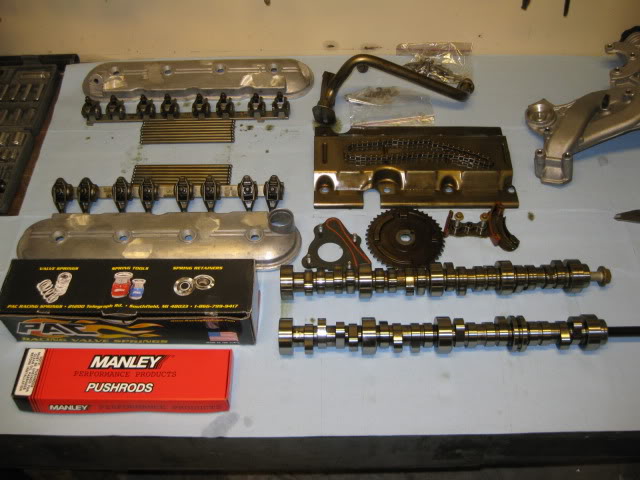
When it came to the camshaft, I chose to stick with a camshaft that was designed for DoD and comes with the springs, pushrods, chain tensioner�
only downside is they would not tell me the specs.
Another LS4 guy installed this same cam and said it was big (peak power in the 6800-7000 range), probably too big, but if he could still get his 3400 lb automatic beast moving with the cam, it should be able to push my 2900 lb fiero with a manual. This cam was advertized to provide a 54 hp increase on the 6.0L� so for better or worse I went big.
Since they would not tell me the specs� I just HAD to find out what they were, so an 18� degree wheel was added to my tool collection.
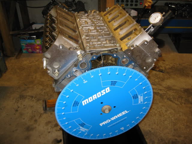
First order of business to degree the stock LS4 cam on cyl #1 (which is a DoD cylinder which might explain why my measurements are slightly different than the internet specs�) I took a degree reading at .006, .050 and every .025 up to max lift up and down for intake and exhaust).
Stock LS4 camshaft specs: 197/197 .286/.286 @ 114LSA
Stock LS4 events @ .050 lobe lift:
IVO (BTDC): -18
IVC (ABDC): 35
EVO (BBDC): 31
EVC (ATDC): -14
I did the same for my aftermarket camshaft and it was 224/231 .332/.338 @ 113 lsa but I also noticed it was really not what I was expecting. Here is an overlay of the two cams with the larger/wider lobes being the aftermarket one. As you can see everything was moved much later in the cycle.

So I spent quite a bit of time checking out other cams of the 224 to 230 duration, comparing where the valve events are for those camshafts and where mine were to figure out a better position in which to install the camshaft. A couple of the comparison cams are as follows:
MTI Stealth II 224/220 (everything at .050 lobe lift)
IVO (BTDC): -4
IVC (ABDC): 48
EVO (BBDC): 46
EVC (ATDC): -6
Comp Cams xer 224/230 (54-444-11 XER273HR)
IVO (BTDC): -1
IVC (ABDC): 45
EVO (BBDC): 50
EVC (ATDC): 0
After much thought and discussion with the other guy running this cam, I chose to install the came with the approximate valve events at .050� lobe lift:
IVO (BTDC): -3.5
IVC (ABDC): 47.5
EVO (BBDC): 46
EVC (ATDC): 5.5
This installed position places the new cam intake center-line right on top of the stock LS4's and pulls the IVO event back down to a more reasonable level for the 5.3 (it is still pretty high). This could be a major mistake, but only time will tell�
only downside is they would not tell me the specs.
Another LS4 guy installed this same cam and said it was big (peak power in the 6800-7000 range), probably too big, but if he could still get his 3400 lb automatic beast moving with the cam, it should be able to push my 2900 lb fiero with a manual. This cam was advertized to provide a 54 hp increase on the 6.0L� so for better or worse I went big.
Since they would not tell me the specs� I just HAD to find out what they were, so an 18� degree wheel was added to my tool collection.
First order of business to degree the stock LS4 cam on cyl #1 (which is a DoD cylinder which might explain why my measurements are slightly different than the internet specs�) I took a degree reading at .006, .050 and every .025 up to max lift up and down for intake and exhaust).
Stock LS4 camshaft specs: 197/197 .286/.286 @ 114LSA
Stock LS4 events @ .050 lobe lift:
IVO (BTDC): -18
IVC (ABDC): 35
EVO (BBDC): 31
EVC (ATDC): -14
I did the same for my aftermarket camshaft and it was 224/231 .332/.338 @ 113 lsa but I also noticed it was really not what I was expecting. Here is an overlay of the two cams with the larger/wider lobes being the aftermarket one. As you can see everything was moved much later in the cycle.
So I spent quite a bit of time checking out other cams of the 224 to 230 duration, comparing where the valve events are for those camshafts and where mine were to figure out a better position in which to install the camshaft. A couple of the comparison cams are as follows:
MTI Stealth II 224/220 (everything at .050 lobe lift)
IVO (BTDC): -4
IVC (ABDC): 48
EVO (BBDC): 46
EVC (ATDC): -6
Comp Cams xer 224/230 (54-444-11 XER273HR)
IVO (BTDC): -1
IVC (ABDC): 45
EVO (BBDC): 50
EVC (ATDC): 0
After much thought and discussion with the other guy running this cam, I chose to install the came with the approximate valve events at .050� lobe lift:
IVO (BTDC): -3.5
IVC (ABDC): 47.5
EVO (BBDC): 46
EVC (ATDC): 5.5
This installed position places the new cam intake center-line right on top of the stock LS4's and pulls the IVO event back down to a more reasonable level for the 5.3 (it is still pretty high). This could be a major mistake, but only time will tell�
The following users liked this post:
LS4eva (09-17-2020)
09-29-2012, 03:19 PM
#6
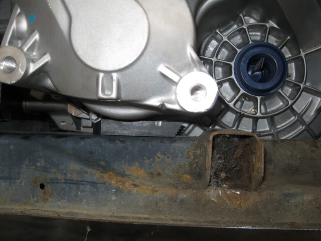
Then it was time for the first of many test fits checking for available room and needed modifications.
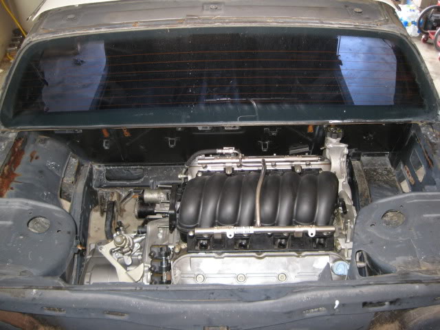
The LS4/F40 combo is a very tight fit with the factory water pump and an unmodified 88 cradle. My mockup chassis has bolt in hinge boxes, so I left them out for this test fit. That is the only deviation from a 100% stock 88 engine bay (other than the battery tray). The elevation and engine placement in the pictures is dictated by clearance issues in several areas. Once these clearance issues are addressed the engine placement/elevation could be moved around a little more.
Overall engine bay view :
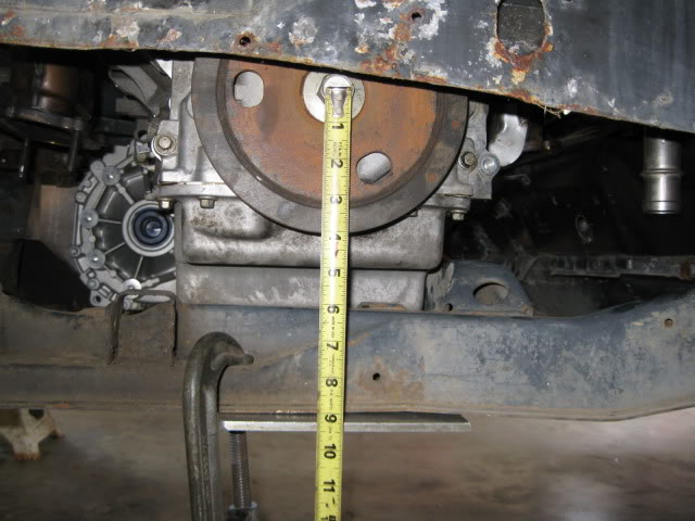
The crankshaft centerline is about 9 1/8" from the bottom of the 88 cradle (height was dictated by clearance issues, but with some modification it can go lower):
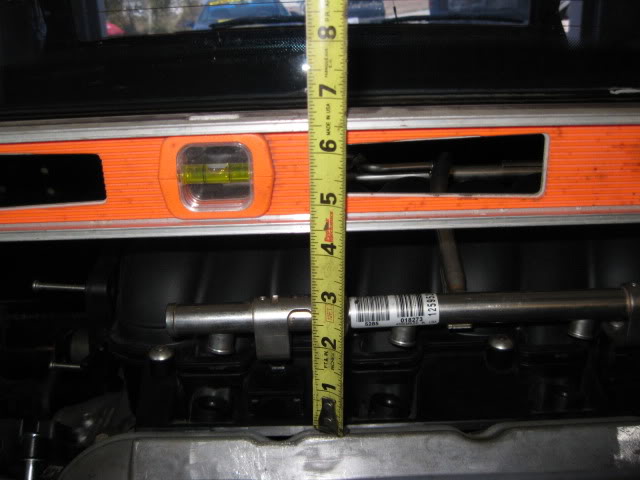
Another reference to elevation is this measurement from the flat top of the strut towers to top most portion of the valve cover:
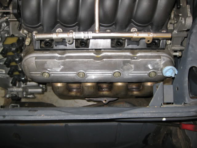
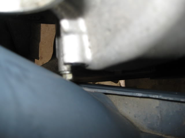
On the engine side of things there are clearance issues with...
Oil fill with dog bone bracket:
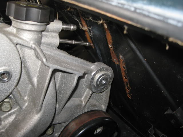
Water pump bolt with strut tower:
Idler bracket with strut tower and balancer to passenger frame rail:
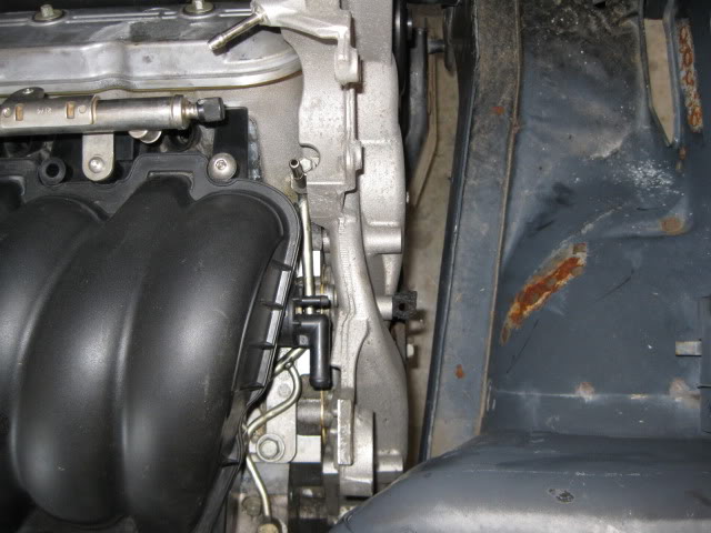
Coolant fill with hinge box and front idler with firewall:
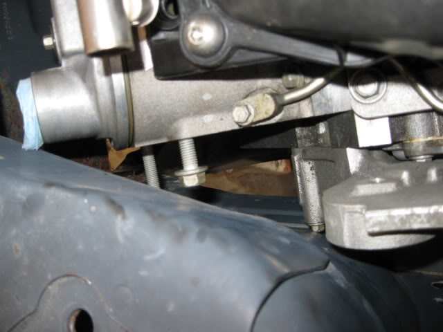
Oil pan and engine mount bracket on cradle (this and the tranny to frame rail dictated the engine elevation to clear everything):
Oil filter to front cradle cross member:
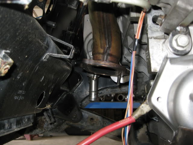
Front exhaust manifold to the double firewall section:
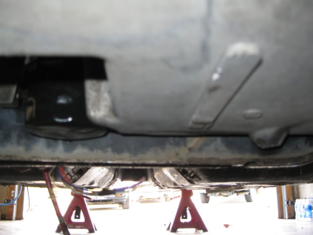
Oil pan to bottom of cradle (about 1"):
Moving on to the transmission side of things:
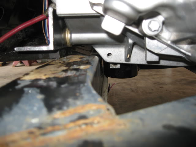
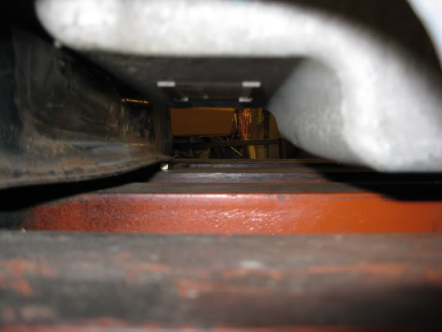
Tranny to driver side frame rail (it is touching):
Tranny to the cradle side rails (notice my shim to level the engine/tranny - this will be the elevation limiter before the bottom of the cradle):
Other important dimensions:
Valve cover to rear firewall = 2 3/16"
C/L crank to C/L of front cradle bolt = 15 5/8 (measured horizontal, not angular)
Bell housing face is offset 5 1/4" from the cradle centerline to the driver side
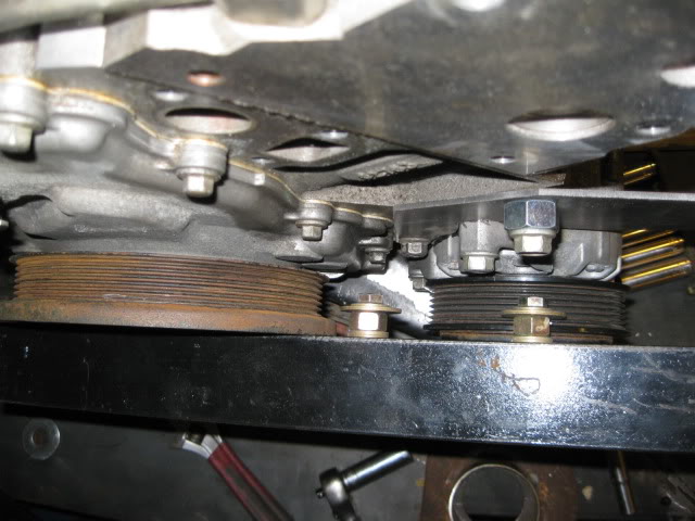
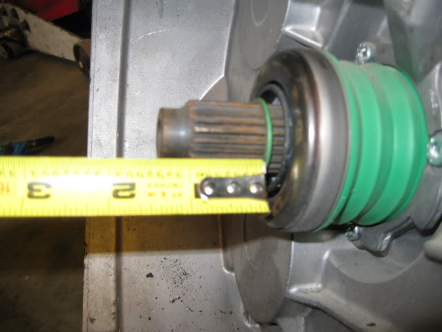
Here is a good comparison between the axle centerlines locations between the F40 and the 4T65. The elevation is pretty close, the F40's axle is close to 2" closer to the engine than the 4T65:
As you can see in the pictures where the engine is sitting is dictated front to back by the idler pulley to firewall & Oil filter to cradle in the front and idler pulley to strut tower clearance to the rear. Side to side placement is tranny to DS frame rail on the left and water pump bolt to the strut tower on the right. Elevation is dictated by the stock cradle engine mount to oil pan interference.
Moving the engine forward will gain more clearance side to side and to the rear of the engine. This is what all the LS4/4T65 swaps done to date have done by notching the cradle for the oil filter and relocating the front idler back an inch or two. Removal of the stock engine mount on the cradle will allow the engine to lower about 1/2" and to go any lower would require some work to the tranny case or cradle side rail.
The LS4/F40 combo is a very tight fit with the factory water pump and an unmodified 88 cradle. My mockup chassis has bolt in hinge boxes, so I left them out for this test fit. That is the only deviation from a 100% stock 88 engine bay (other than the battery tray). The elevation and engine placement in the pictures is dictated by clearance issues in several areas. Once these clearance issues are addressed the engine placement/elevation could be moved around a little more.
Overall engine bay view :
The crankshaft centerline is about 9 1/8" from the bottom of the 88 cradle (height was dictated by clearance issues, but with some modification it can go lower):
Another reference to elevation is this measurement from the flat top of the strut towers to top most portion of the valve cover:
On the engine side of things there are clearance issues with...
Oil fill with dog bone bracket:
Water pump bolt with strut tower:
Idler bracket with strut tower and balancer to passenger frame rail:
Coolant fill with hinge box and front idler with firewall:
Oil pan and engine mount bracket on cradle (this and the tranny to frame rail dictated the engine elevation to clear everything):
Oil filter to front cradle cross member:
Front exhaust manifold to the double firewall section:
Oil pan to bottom of cradle (about 1"):
Moving on to the transmission side of things:
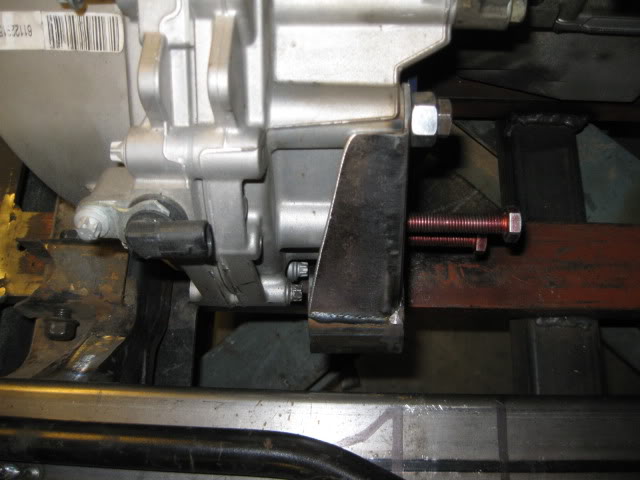
Tranny to driver side frame rail (it is touching):
Tranny to the cradle side rails (notice my shim to level the engine/tranny - this will be the elevation limiter before the bottom of the cradle):
Other important dimensions:
Valve cover to rear firewall = 2 3/16"
C/L crank to C/L of front cradle bolt = 15 5/8 (measured horizontal, not angular)
Bell housing face is offset 5 1/4" from the cradle centerline to the driver side
Here is a good comparison between the axle centerlines locations between the F40 and the 4T65. The elevation is pretty close, the F40's axle is close to 2" closer to the engine than the 4T65:
As you can see in the pictures where the engine is sitting is dictated front to back by the idler pulley to firewall & Oil filter to cradle in the front and idler pulley to strut tower clearance to the rear. Side to side placement is tranny to DS frame rail on the left and water pump bolt to the strut tower on the right. Elevation is dictated by the stock cradle engine mount to oil pan interference.
Moving the engine forward will gain more clearance side to side and to the rear of the engine. This is what all the LS4/4T65 swaps done to date have done by notching the cradle for the oil filter and relocating the front idler back an inch or two. Removal of the stock engine mount on the cradle will allow the engine to lower about 1/2" and to go any lower would require some work to the tranny case or cradle side rail.
09-29-2012, 03:23 PM
#7
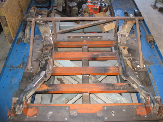
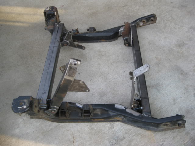
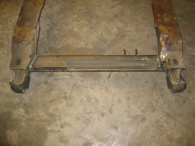
After the test fit, I knew there needed to be some modifications to at least the front cross member, so I took one the 88 cradle and did this to it:
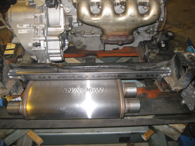
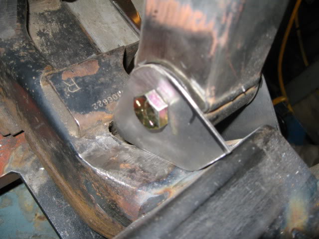
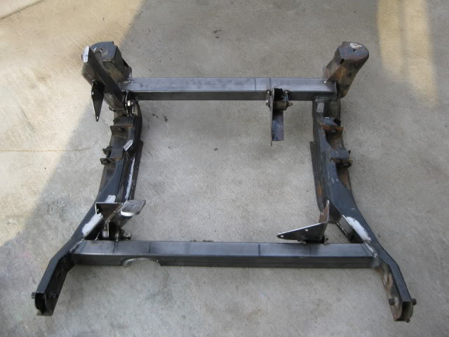
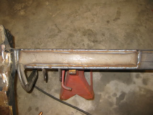
Then put it in the 88 cradle fixture and welded in new 2x3x1/8” cross members front and rear. The front one was moved further forward and the rear one was raised to increase room for a wider/thicker muffler.
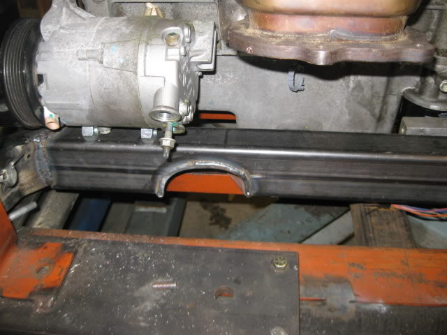
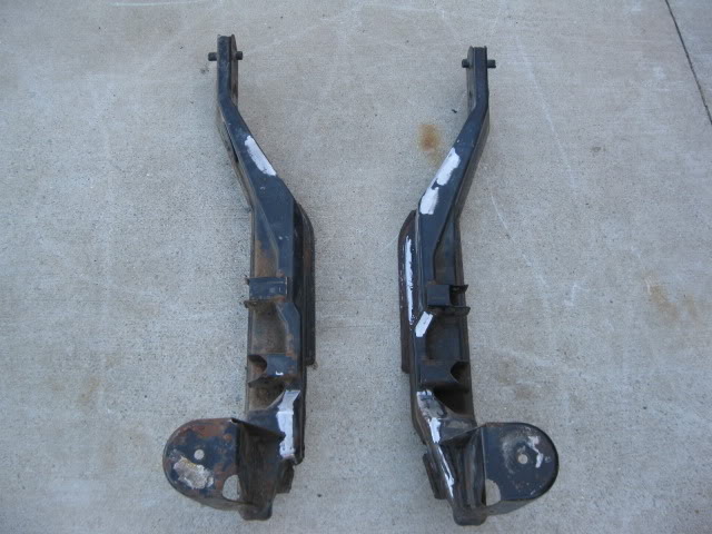
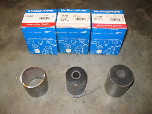
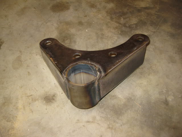
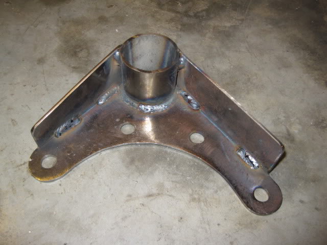
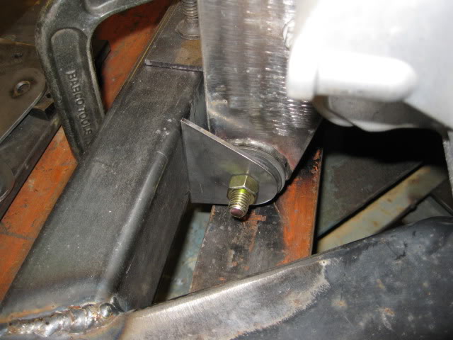
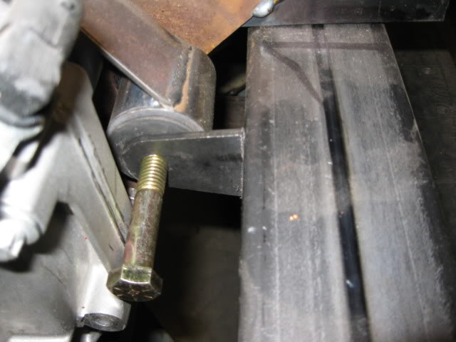
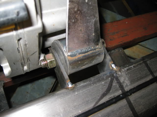
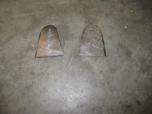
For the mounts, I will be using a 4 corner rubber mount system using the FB235 mounts that can be purchased for 6.99. These mounts will be pressed into a metal sleeve and the sleeve welded to the brackets.
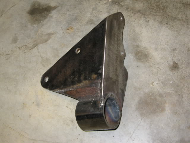
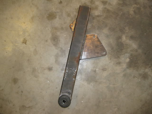
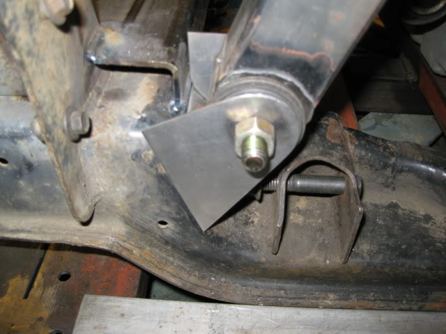
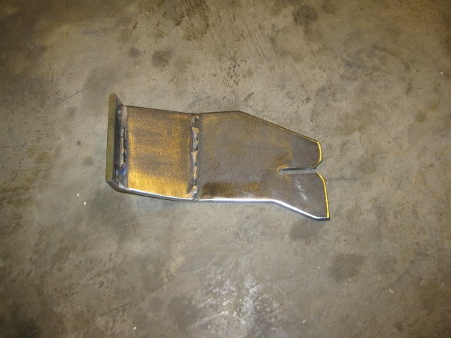
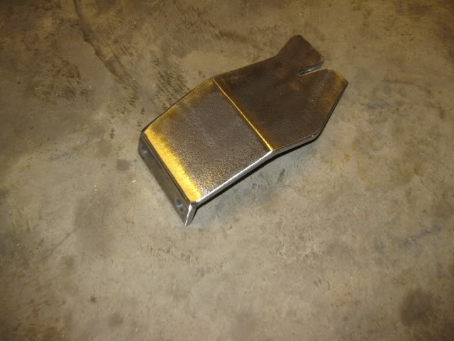
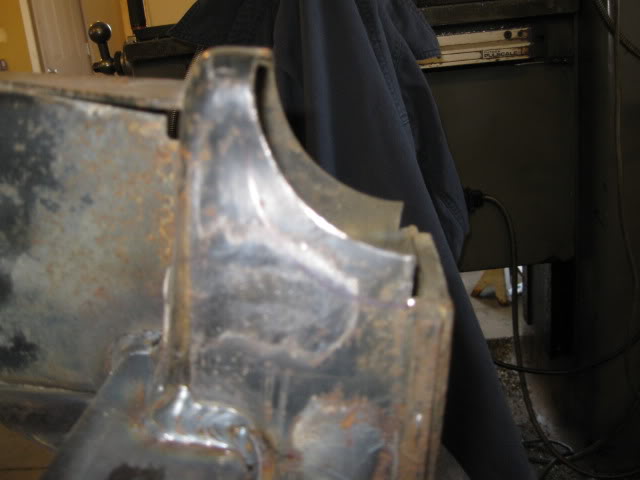
Here is the front transmission mount bracket:
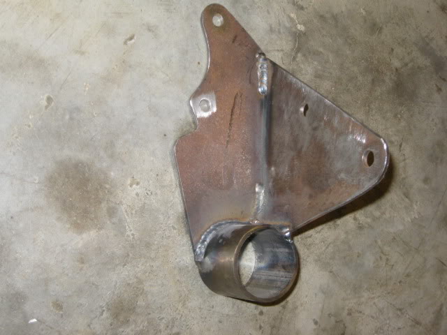
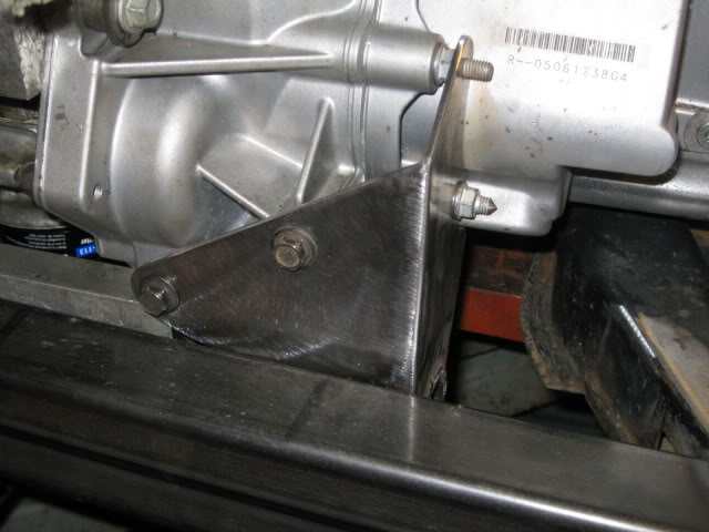
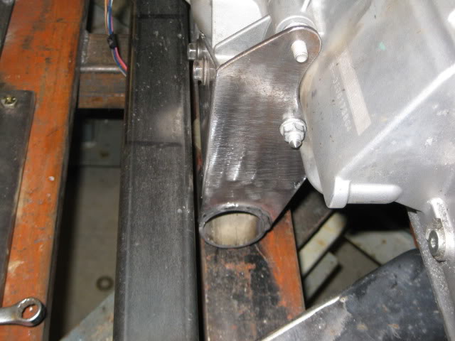
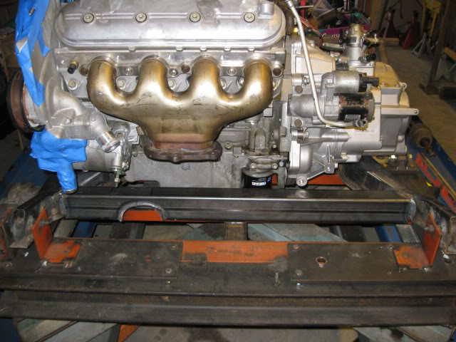
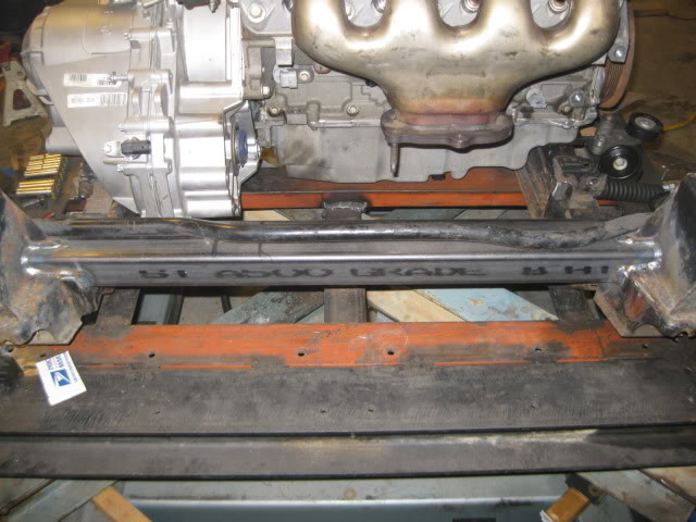
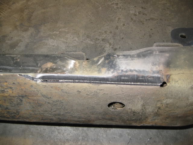
Here is the rear transmission bracket:
After the next test fit, I will fabricate the tabs that will be welded to the cross members to finish up the mounts.
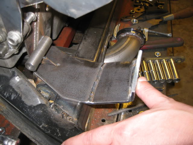
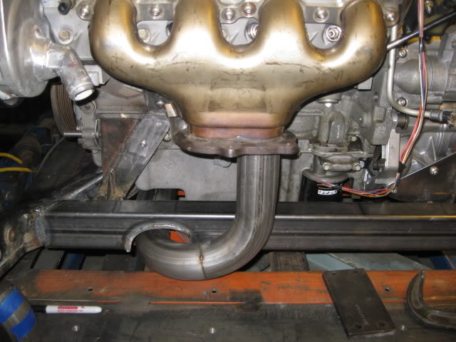
Here is a shot of the exhaust pipe clearance under the oil pan:
Then put it in the 88 cradle fixture and welded in new 2x3x1/8” cross members front and rear. The front one was moved further forward and the rear one was raised to increase room for a wider/thicker muffler.
For the mounts, I will be using a 4 corner rubber mount system using the FB235 mounts that can be purchased for 6.99. These mounts will be pressed into a metal sleeve and the sleeve welded to the brackets.
Here is the front transmission mount bracket:
Here is the rear transmission bracket:
After the next test fit, I will fabricate the tabs that will be welded to the cross members to finish up the mounts.
Here is a shot of the exhaust pipe clearance under the oil pan:
The following users liked this post:
LS4eva (09-17-2020)
Trending Topics
 09-29-2012, 03:34 PM
#9
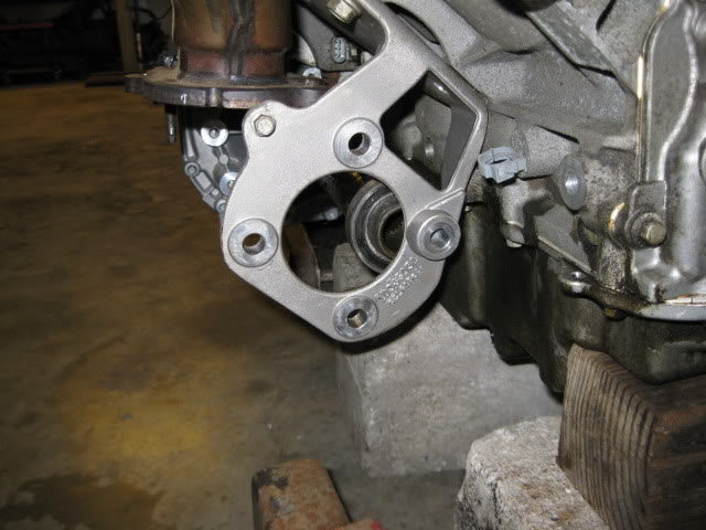
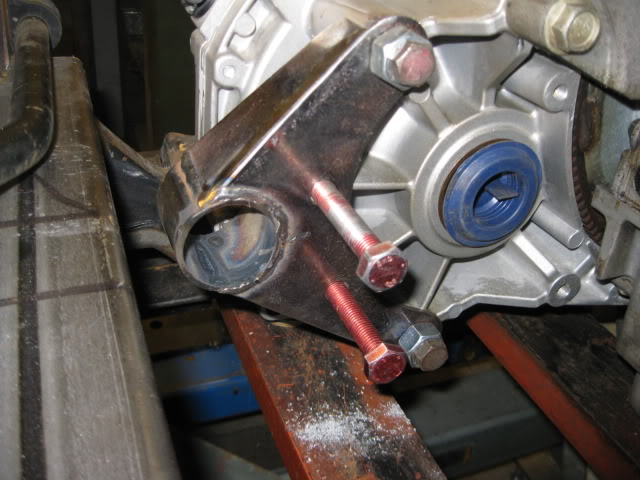
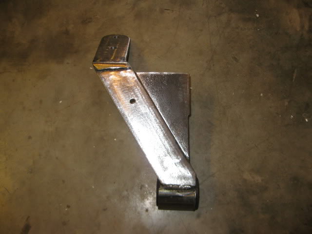
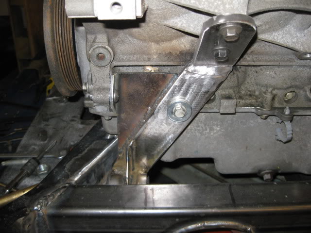
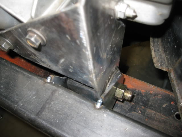
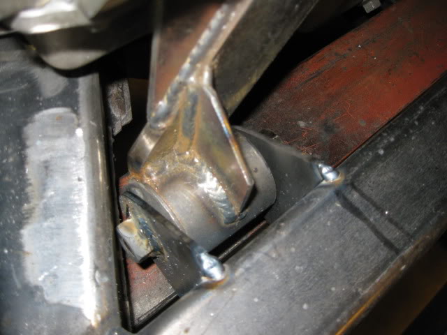
The next order of business was to figure out the engine side mounts. Here are a couple work in progress picture of the rear engine mount. Just like the other 2 mounts, 4 bolt holes are used (one at the very top you can not see yet) to spread the load:
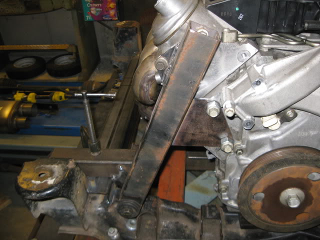
On the rear cross member is a locating tool for this mount... it locates the bottom bushing in the same location as the rear transmission mount. Doing this isn't required, but I try to keep the mounts co-linear whenever possible. I also like to position the mounts as far apart as possible to better control any drive train movement without needing any top side supports.
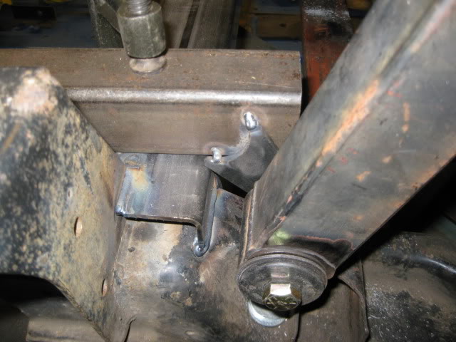
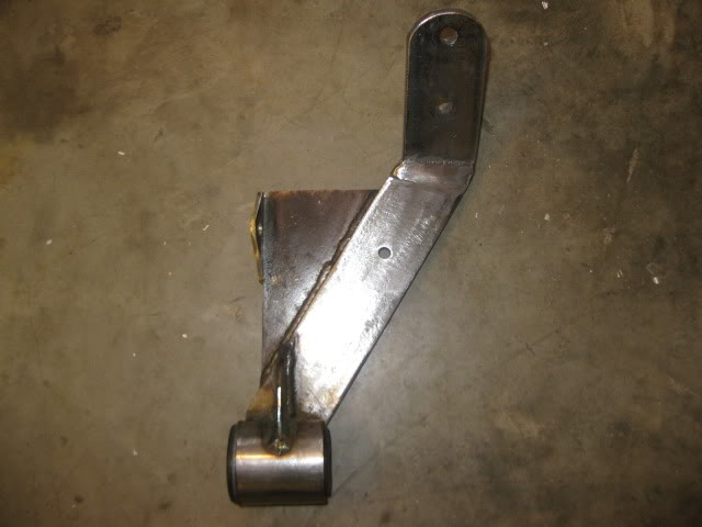
Here is the mostly completed rear mount:
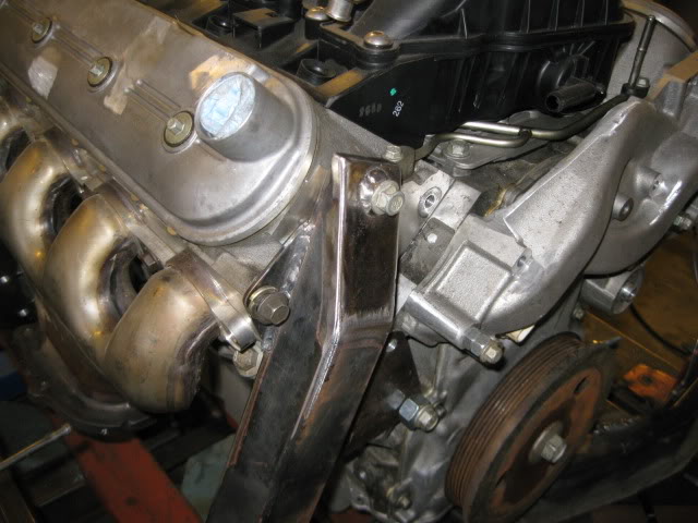
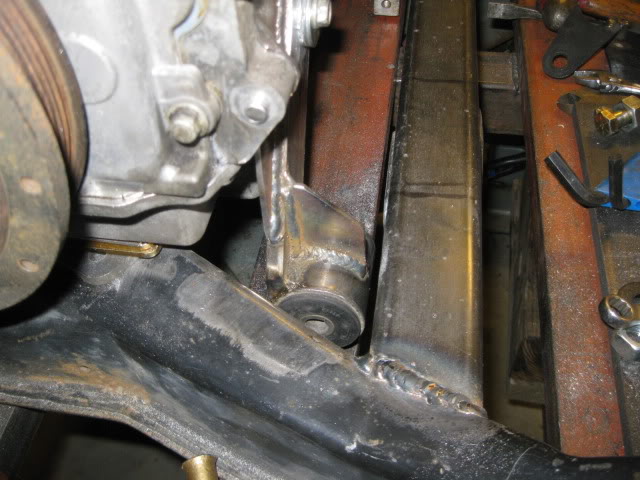
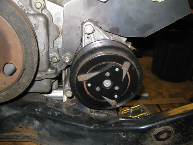
On the front side of the engine, there isn't much room between the block and AC compressor, but some 3/8" x 2" steel bar will fit and be plenty stiff. I was able to use 4 bolts on this mount as well to help spread the load. I also made another bushing locator so this bushing is co-linear with the front transmission bushing.
On the rear cross member is a locating tool for this mount... it locates the bottom bushing in the same location as the rear transmission mount. Doing this isn't required, but I try to keep the mounts co-linear whenever possible. I also like to position the mounts as far apart as possible to better control any drive train movement without needing any top side supports.
Here is the mostly completed rear mount:
On the front side of the engine, there isn't much room between the block and AC compressor, but some 3/8" x 2" steel bar will fit and be plenty stiff. I was able to use 4 bolts on this mount as well to help spread the load. I also made another bushing locator so this bushing is co-linear with the front transmission bushing.
09-29-2012, 03:48 PM
#11
Before I locked down the front/rear placement of the drivetrain, I had to figure out the accessory placement and rework just about the entire thing.
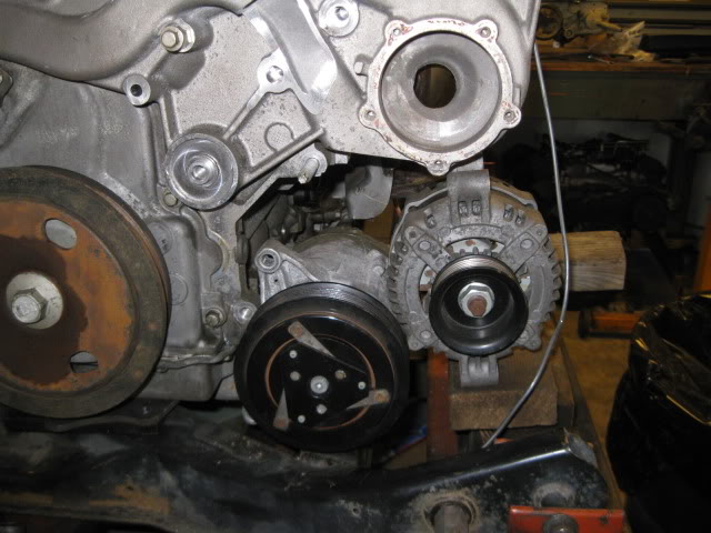
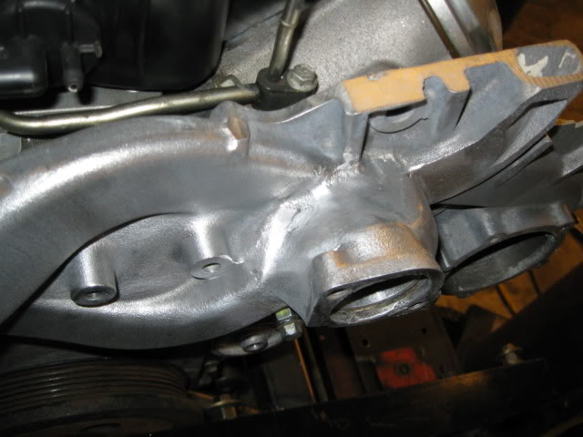
The stock LS4 water pump is compact in that it protrudes very little beyond the LS4 balancer. The thinness helps ensure everything fits within the frame rails, but at an expense. The LS4 coolant fill location hits the stock deck lid spring box and the swaps so far have either moved the box or modified the water pump (or both). I chose to modify the water pump to fix the coolant fill issue, address the location for the alternator and the cluttered collection of hoses at the base of the LS4 water pump. All completed LS4 swaps have either trimmed the passenger frame rail to mount it on the rear of the engine down low (right above the axle) or use WCF reverse cantilevered mount to hang it over the old battery location. I am after a clean and simple design and wanted the alternator out of sight and alongside the alternator (like all my other swaps have been). This avoids the frame rail mod and keeps the alternator hidden.
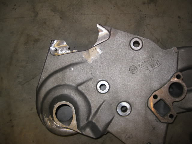
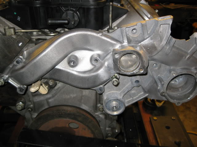
Everything in blue is going away:
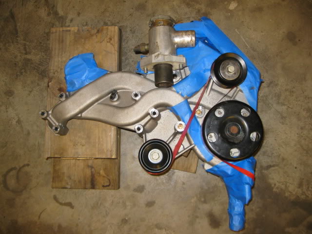
Once the majority of it is trimmed:
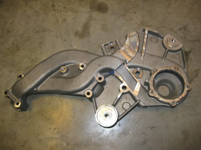
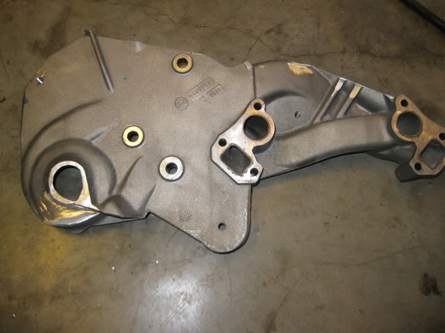
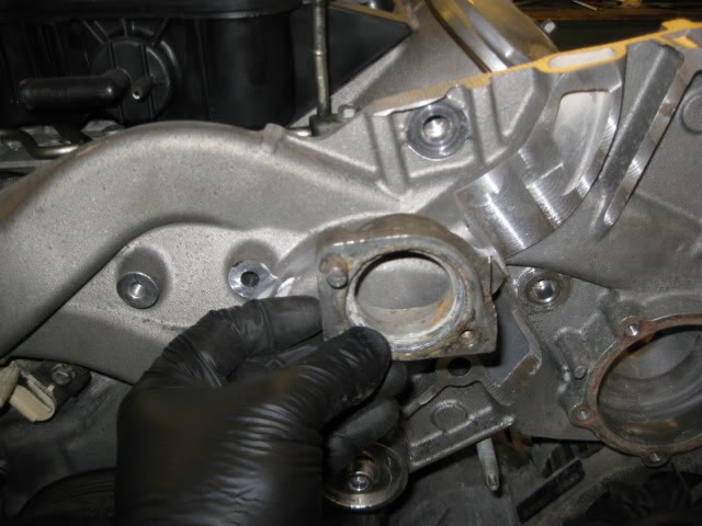
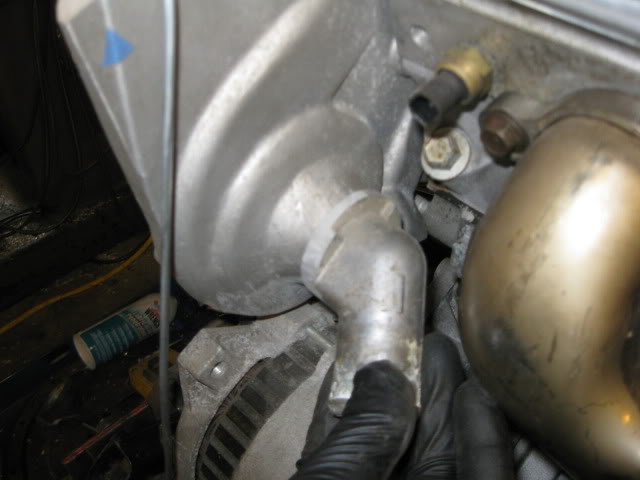
As you look at the pictures above, you can see the outlet for the water pump goes to the top and the portion removed at the bottom was just the passage to the thermostat housing (and the thermostat housing). Before you all freak out, here is my new (chunk of a 4.3 intake manifold) thermostat housing that will be welded to the LS4 water pump housing:
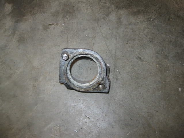

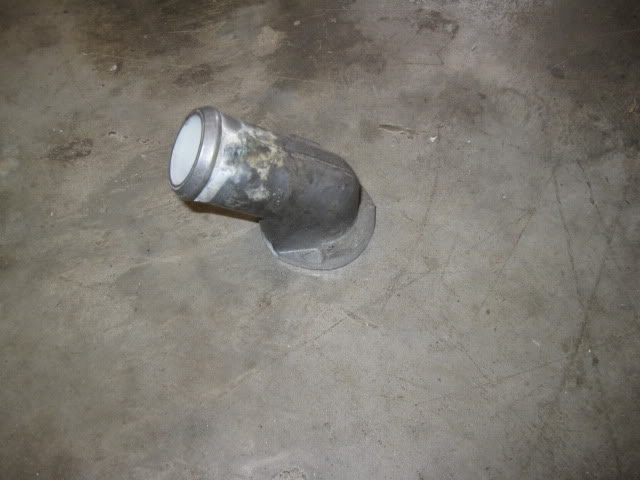
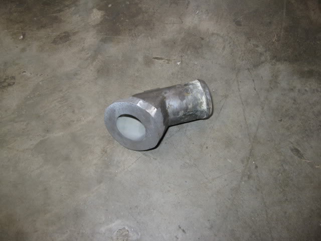
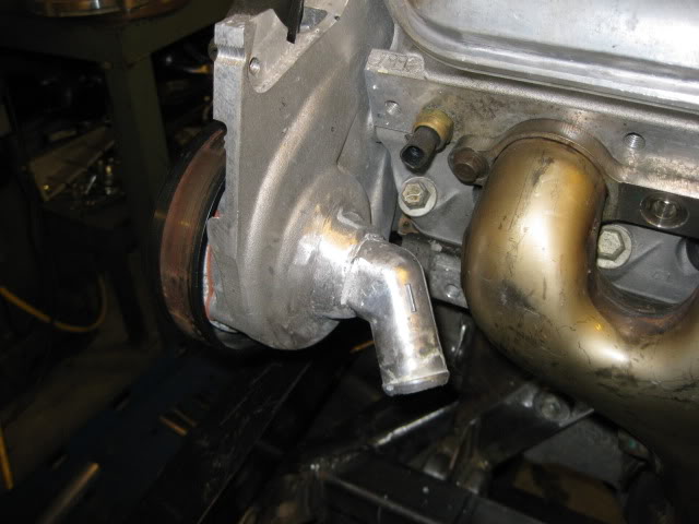
Here is the nipple (another modified thermostat housing) that will be welded on the back side of the water pump for the coolant inlet. I still need to shorten it some to gain more clearance to the exhaust (that is the outer heat shield, not the primary tube):
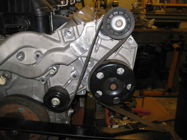
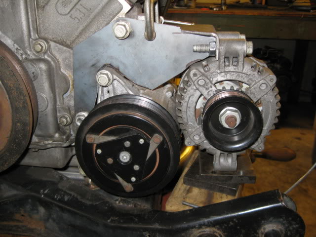
Here is a rough approximation of the belt drive for the accessories:
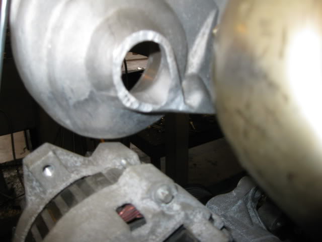
If you look close at this picture you can see a piece of 1/8" wire alongside the alternator, the lower portion of this represents the slight indent in the double firewall section that gives just enough room (might move the engine/tranny rearward about 3/8" to gain more clearance when I finalize the mount locations on the cradle.
Here is where I placed the new belt tensioner:
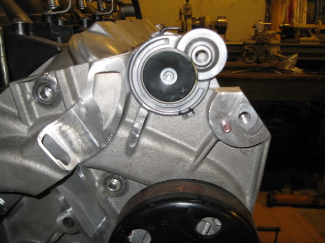
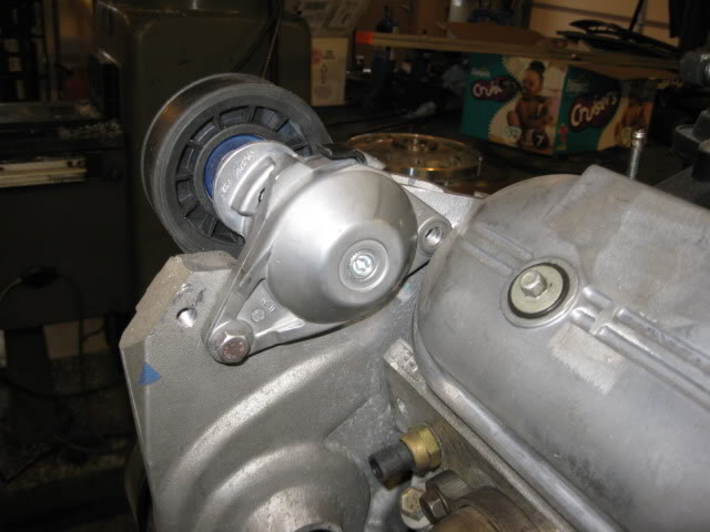
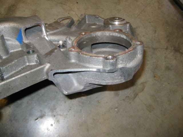
This location places the tensioner on the slack side of the belt and places both bolts in an area of the water pump casting that is quite thick. This will provides ample material for threads as well as milling about 1/8� off the back side to level out the area where the tensioner mounts (and give the front bolt clearance to the valve cover). I still need to make a spacer for the idler to position it in line with the balancer and might relocated the bottom idler by the balancer up about 1/2" to give more room between the two belts.
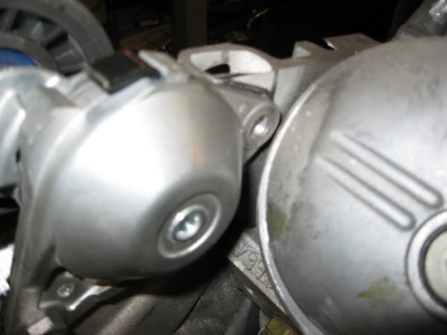
Here the backside was machined for the tensioner:
There should be enough room for the stainless steel button head now.
The belts do not really get much closer as the tensioner moves:
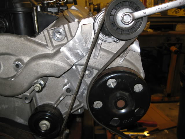
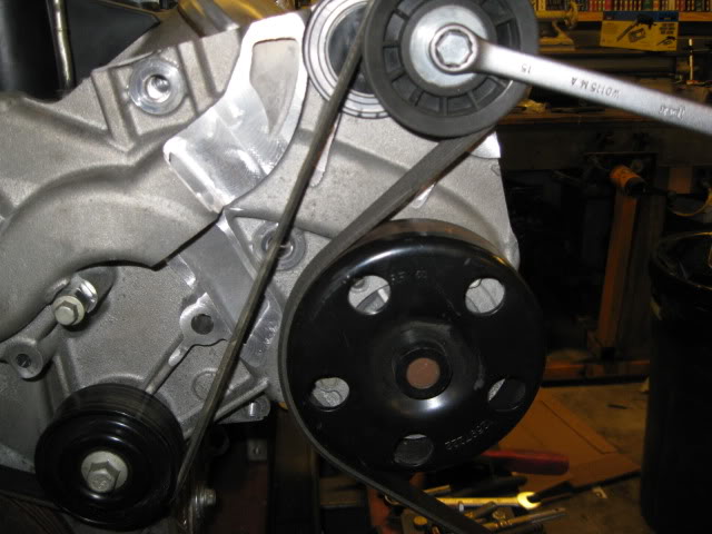
I still need to do some more clearancing to the boss on the water pump so the tensioner has full range of motion. Right now it takes up about 1" of belt slack and I would like to to be closer to 2".
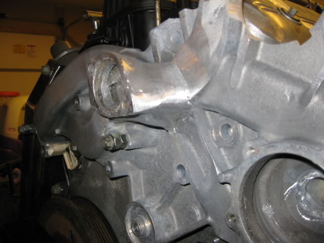
The nipple for the water pump inlet was welded in place and the welds cleaned up:
Welded and smoothed the new (traditional) thermostat housing:
The stock LS4 water pump is compact in that it protrudes very little beyond the LS4 balancer. The thinness helps ensure everything fits within the frame rails, but at an expense. The LS4 coolant fill location hits the stock deck lid spring box and the swaps so far have either moved the box or modified the water pump (or both). I chose to modify the water pump to fix the coolant fill issue, address the location for the alternator and the cluttered collection of hoses at the base of the LS4 water pump. All completed LS4 swaps have either trimmed the passenger frame rail to mount it on the rear of the engine down low (right above the axle) or use WCF reverse cantilevered mount to hang it over the old battery location. I am after a clean and simple design and wanted the alternator out of sight and alongside the alternator (like all my other swaps have been). This avoids the frame rail mod and keeps the alternator hidden.
Everything in blue is going away:
Once the majority of it is trimmed:
As you look at the pictures above, you can see the outlet for the water pump goes to the top and the portion removed at the bottom was just the passage to the thermostat housing (and the thermostat housing). Before you all freak out, here is my new (chunk of a 4.3 intake manifold) thermostat housing that will be welded to the LS4 water pump housing:
Here is the nipple (another modified thermostat housing) that will be welded on the back side of the water pump for the coolant inlet. I still need to shorten it some to gain more clearance to the exhaust (that is the outer heat shield, not the primary tube):
Here is a rough approximation of the belt drive for the accessories:
If you look close at this picture you can see a piece of 1/8" wire alongside the alternator, the lower portion of this represents the slight indent in the double firewall section that gives just enough room (might move the engine/tranny rearward about 3/8" to gain more clearance when I finalize the mount locations on the cradle.
Here is where I placed the new belt tensioner:
This location places the tensioner on the slack side of the belt and places both bolts in an area of the water pump casting that is quite thick. This will provides ample material for threads as well as milling about 1/8� off the back side to level out the area where the tensioner mounts (and give the front bolt clearance to the valve cover). I still need to make a spacer for the idler to position it in line with the balancer and might relocated the bottom idler by the balancer up about 1/2" to give more room between the two belts.
Here the backside was machined for the tensioner:
There should be enough room for the stainless steel button head now.
The belts do not really get much closer as the tensioner moves:
I still need to do some more clearancing to the boss on the water pump so the tensioner has full range of motion. Right now it takes up about 1" of belt slack and I would like to to be closer to 2".
The nipple for the water pump inlet was welded in place and the welds cleaned up:
Welded and smoothed the new (traditional) thermostat housing:
09-29-2012, 03:53 PM
#12
Now that I knew I could fit the alternator where it needed to be and defined the engine placement front/rear, it was time to make all the tabs for the engine/transmission mounts.
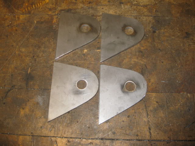
The 4 mount tabs for the front mounts:
For the rear transmission mount, the tabs are slightly modified off the shelf items:
3 of the 4 mounts are done and the 4th one the templates are made.
Here are the two templates for the rear engine mount:
Mounts are done and fully welded. These should hold up to whatever amount of HP I want to throw at them (might run NOS or go turbo at a later date), but are still rubber mounted to reduce shock loading:
09-29-2012, 04:04 PM
#13
On The Tree
Join Date: Jul 2011
Posts: 168
Likes: 0
Received 0 Likes
on
0 Posts
You really need to do something about the fender gap. That's like half a foot. Otherwise looks awesome.
I wish GM would revive the Fiero and make another mid-engine car like this, except with a V8 from the factory.
I wish GM would revive the Fiero and make another mid-engine car like this, except with a V8 from the factory.
09-29-2012, 04:10 PM
#14
Been thinking about the AC and Alternator mounting for quite some time and think I have it figured out. First order of business was to mock up a relatively stiff upper support to hold the AC compressor in the right general location so I could finalize the bottom and backside mounting points. Also used my angle pulley alignment tool to ensure the AC compressor was at the proper depth:
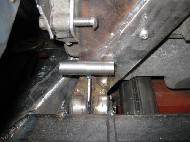
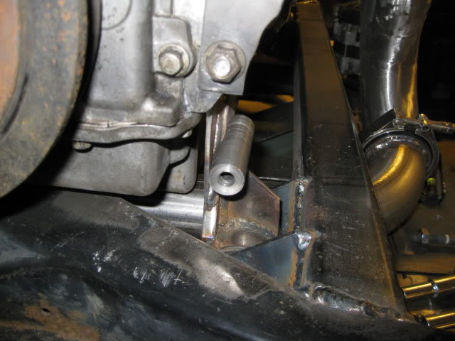
I picked up some metric nuts, then tuned one down to fit inside a tube (a section of an 88 trailing link tube), welded it in place and then turned the weld down smooth. I had to mill a flat on the back side to clear the thicker portion of the front engine bracket. This tube will act as the lower AC compressor mount. It is just tack welded to the front engine bracket, but it will be fully welded:
For the rear mount, I am planning to weld a nut into a 1x1 square tube and then cut its legs to fit up against the thick portion of the front engine mount:
The rear A/C support boss is tacked into place and that restores the AC compressor to 3 points of attachment just like stock:
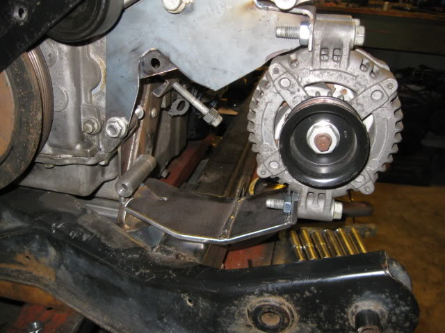
I decided to incorporate the top portion of the alternator bracket with the 1/8" plate that supports the AC bracket. So I bent some more 1/8" material, bent it a couple of times to provide some stiffness and clear the engine block, then tack it to the upper AC bracket:
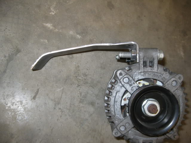
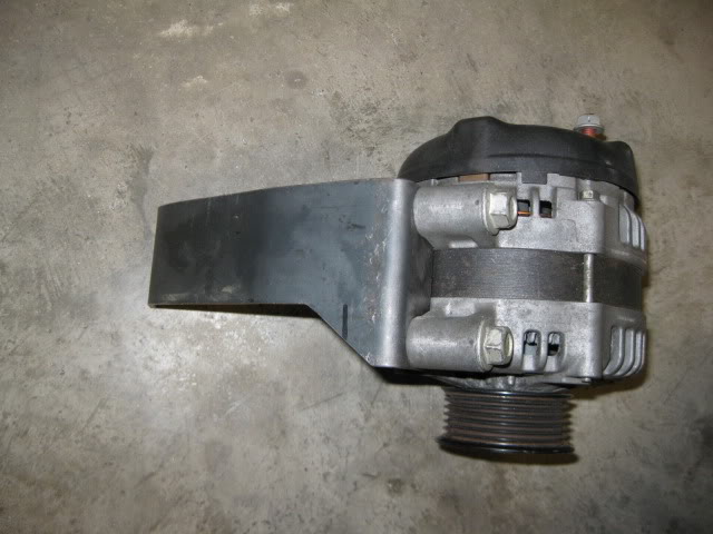
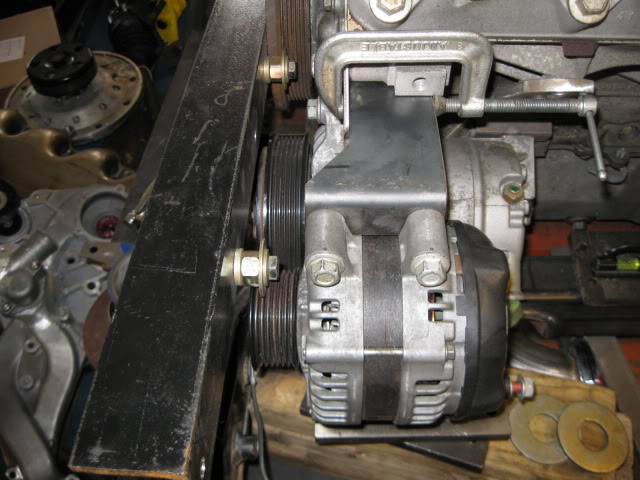
Here is the lower Alternator bracket. I still need to weld this lower plate into the front engine mount/AC bracket and notch the cradle directly under the bracket to allow 1/4" movement, but it is starting to take shape:
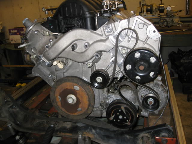
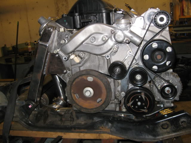
Accessory drive went from this:
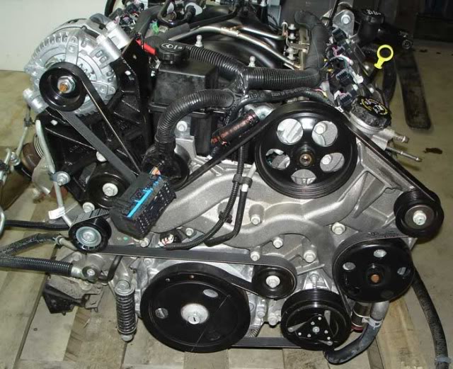
To this:
114" belt to 80" belt
5 idlers, reduced to 3
Alternator up top at rear of engine to down low at front
PS pump from up top to in trash can (actually just sitting on the shelf)
Lots of stuff visible on top, to just the new tension idler
I picked up some metric nuts, then tuned one down to fit inside a tube (a section of an 88 trailing link tube), welded it in place and then turned the weld down smooth. I had to mill a flat on the back side to clear the thicker portion of the front engine bracket. This tube will act as the lower AC compressor mount. It is just tack welded to the front engine bracket, but it will be fully welded:
For the rear mount, I am planning to weld a nut into a 1x1 square tube and then cut its legs to fit up against the thick portion of the front engine mount:
The rear A/C support boss is tacked into place and that restores the AC compressor to 3 points of attachment just like stock:
I decided to incorporate the top portion of the alternator bracket with the 1/8" plate that supports the AC bracket. So I bent some more 1/8" material, bent it a couple of times to provide some stiffness and clear the engine block, then tack it to the upper AC bracket:
Here is the lower Alternator bracket. I still need to weld this lower plate into the front engine mount/AC bracket and notch the cradle directly under the bracket to allow 1/4" movement, but it is starting to take shape:
Accessory drive went from this:
To this:
114" belt to 80" belt
5 idlers, reduced to 3
Alternator up top at rear of engine to down low at front
PS pump from up top to in trash can (actually just sitting on the shelf)
Lots of stuff visible on top, to just the new tension idler
09-29-2012, 04:59 PM
#16
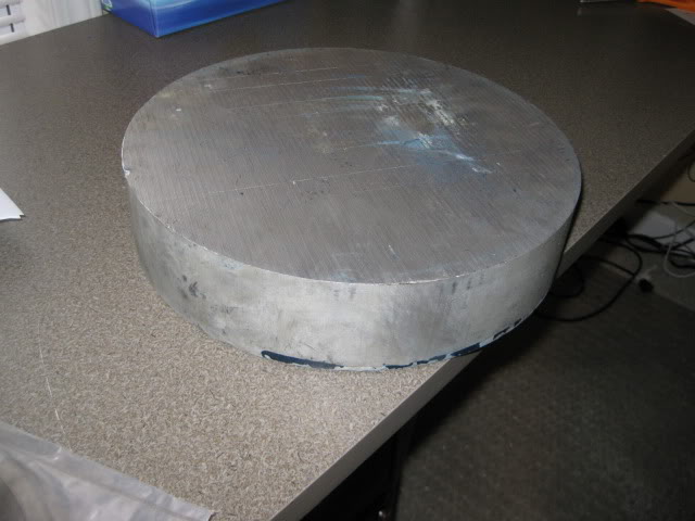
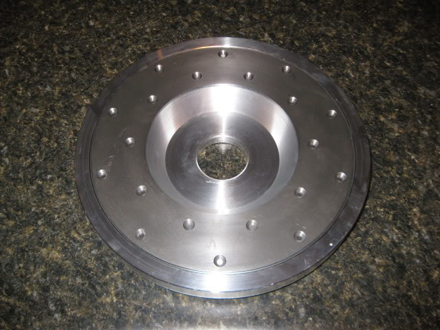
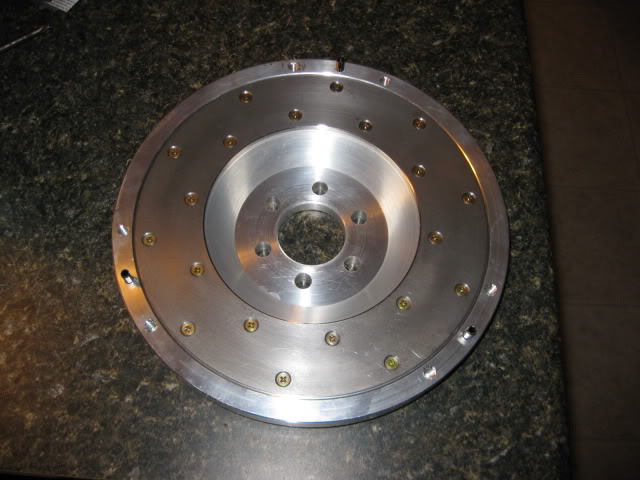
There is no off the shelf 142 tooth LS(x) flywheel available, so I made one that uses Ford Ranger 10" clutch (largest one with the right input shaft spline and would fit within the transmission) specifically for the LS4/F40 application. Took about 12 hrs of total machining for all the processes, but I was doing it the manual way...
My new favorite tool! I need to get me one of these bad boys. It was a lot more fun using it vs. my dinky southbend lathe.
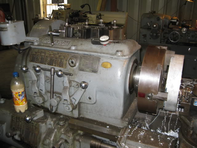
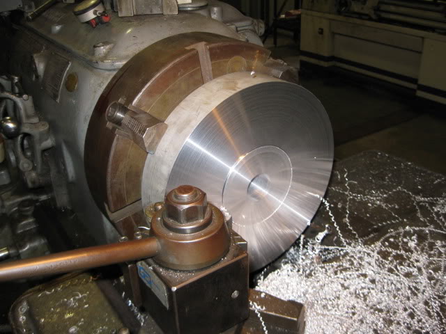
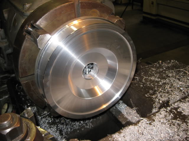
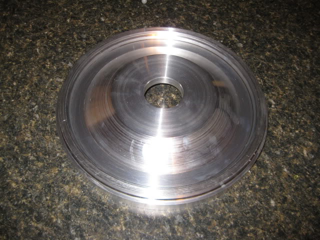
After about 6 hrs running a large lathe... phase 1 of the flywheel machining is complete:
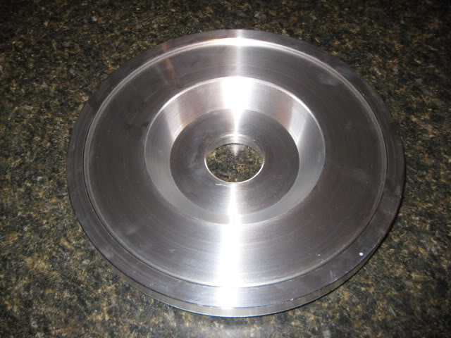
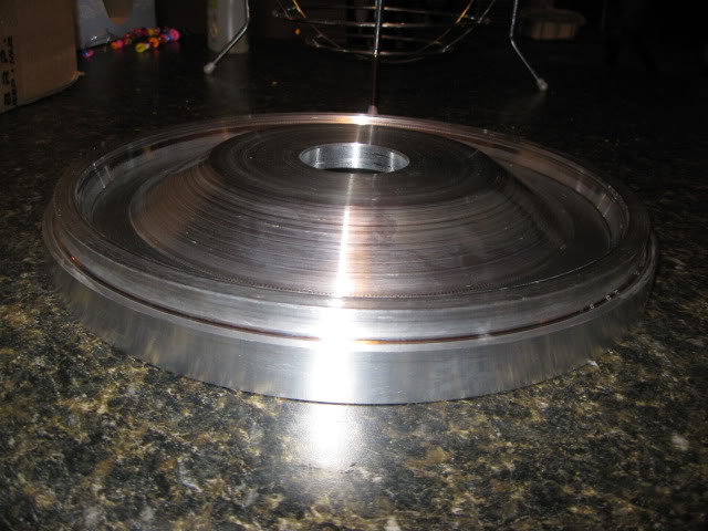
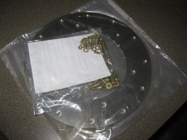
With the wear strip just sitting in place:
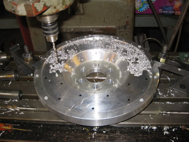
After the flywheel had its center dial indicated, all the holes were drilled via X-Y coordinates from the print. For the wear strip I put it in place and used a sharpie to mark the general locations of the holes to help validate proper hole placement. When drilling 29 holes and each hole has an X and Y coordinate to the X.XXXX values... it is easy to transpose or misread the values.
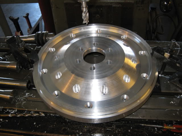
Here is a pic after I installed the alignment pins:
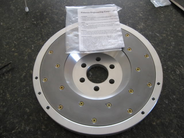
Ring gear is now installed:
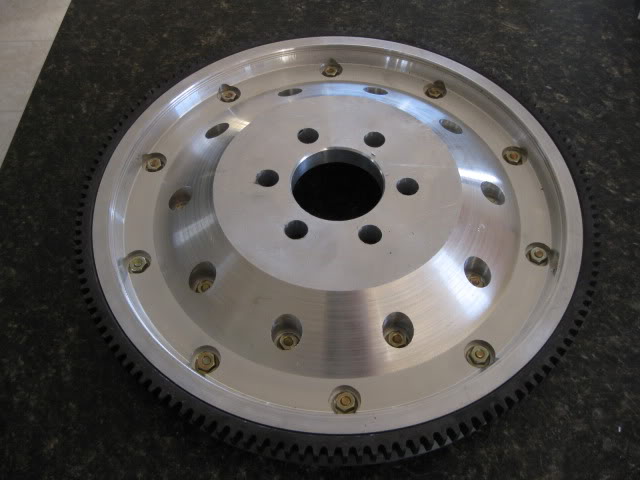
I took it to the same place I dyno'd my SBC fiero to have the balance checked and it came out nearly perfect... no need to remove any additional material to balance it.
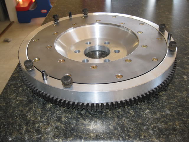
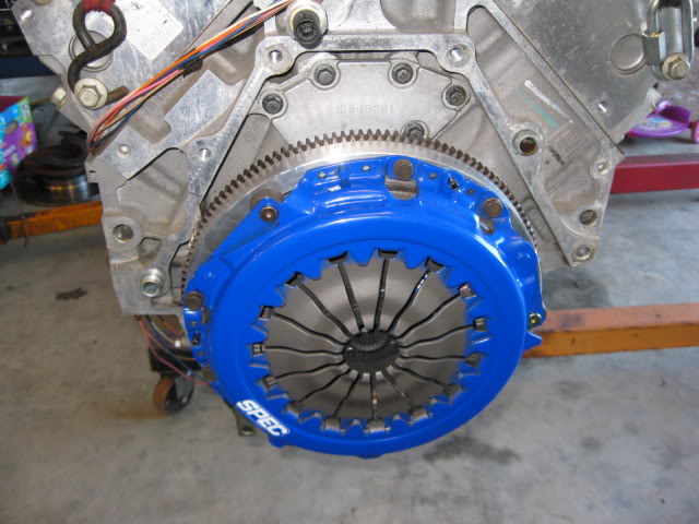
Then I played with the flywheel to confirm it fits the engine and the clutch combo will clear the transmission:
Test fit of old clutch:
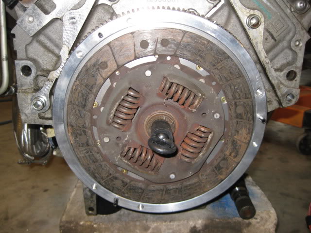
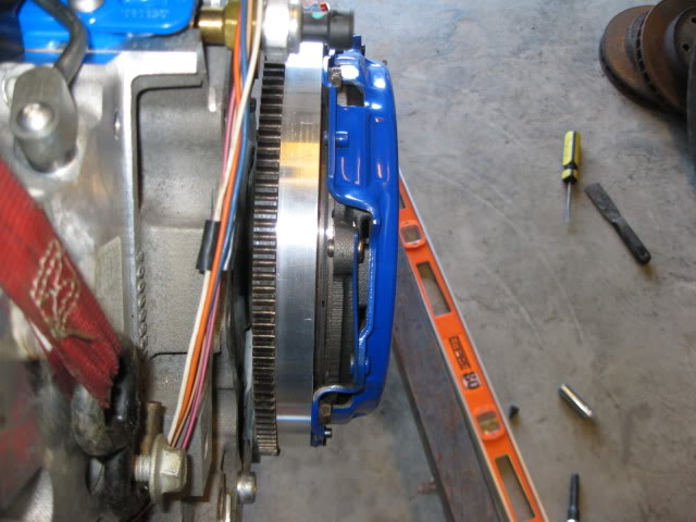
With everything assembled, I was able to spin the engine over about 10 times by hand w/o any rubbing/scraping:
I had put an o-ring on the input shaft to see how deep the clutch hub rests on the shaft... about 1":
Here is the clutch! The list price was $639, but I was able to get it for $575 shipped through LMPerformance.com. This is the 2nd most expensive part for this swap ($749 for the Camshaft kit was #1) excluding the original purchase price the engine...
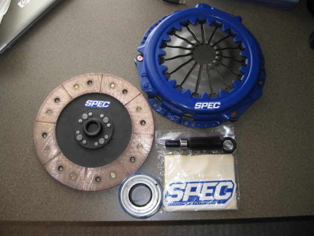
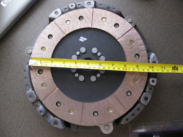
The clutch disk measures at 9 13/16" at the friction material (listed as a 10" clutch) and is one of the largest diameter clutches you can get for this application w/o mixing/matching disks and pressure plates or getting into some trick self-adjusting pressure plates.
It weighs in at 16.52 lbs on the wife's 30 lb postal scales, so the combined flywheel/clutch/pressure plate will be 27.7lbs... which is about 15 lbs lighter (and the flywheel about 1" smaller diameter) than my old SBC flywheel/clutch/pressure plate setup or about 35% lighter... that should help free up some more whp!
For comparison:
Stock 2.8 fiero flywheel/clutch/pressure plate setup is 30.65 lbs.
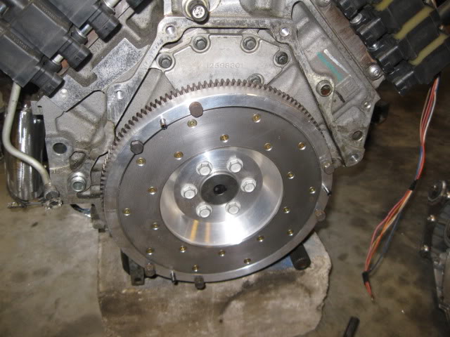
Flywheel installed:
My new favorite tool! I need to get me one of these bad boys. It was a lot more fun using it vs. my dinky southbend lathe.
After about 6 hrs running a large lathe... phase 1 of the flywheel machining is complete:
With the wear strip just sitting in place:
After the flywheel had its center dial indicated, all the holes were drilled via X-Y coordinates from the print. For the wear strip I put it in place and used a sharpie to mark the general locations of the holes to help validate proper hole placement. When drilling 29 holes and each hole has an X and Y coordinate to the X.XXXX values... it is easy to transpose or misread the values.
Here is a pic after I installed the alignment pins:
Ring gear is now installed:
I took it to the same place I dyno'd my SBC fiero to have the balance checked and it came out nearly perfect... no need to remove any additional material to balance it.
Then I played with the flywheel to confirm it fits the engine and the clutch combo will clear the transmission:
Test fit of old clutch:
With everything assembled, I was able to spin the engine over about 10 times by hand w/o any rubbing/scraping:
I had put an o-ring on the input shaft to see how deep the clutch hub rests on the shaft... about 1":
Here is the clutch! The list price was $639, but I was able to get it for $575 shipped through LMPerformance.com. This is the 2nd most expensive part for this swap ($749 for the Camshaft kit was #1) excluding the original purchase price the engine...
The clutch disk measures at 9 13/16" at the friction material (listed as a 10" clutch) and is one of the largest diameter clutches you can get for this application w/o mixing/matching disks and pressure plates or getting into some trick self-adjusting pressure plates.
It weighs in at 16.52 lbs on the wife's 30 lb postal scales, so the combined flywheel/clutch/pressure plate will be 27.7lbs... which is about 15 lbs lighter (and the flywheel about 1" smaller diameter) than my old SBC flywheel/clutch/pressure plate setup or about 35% lighter... that should help free up some more whp!
For comparison:
Stock 2.8 fiero flywheel/clutch/pressure plate setup is 30.65 lbs.
Flywheel installed:
Last edited by fieroguru; 07-03-2016 at 09:42 AM.
09-29-2012, 05:17 PM
#17
To catch up on the comments so far:
Thanks for the compliment!
Here is a teaser pic:
Thanks for the compliment!
I loved my 86 Vette (406 ci, TPIS MiniRam, 4+3 trans) and put 60K miles on it in the 6 years I owned it. I sold it to buy the shop next to my house and narrow my focus to 88 Fieros.
Thanks for the compliment!
The car is sitting without engine/transmission, but it will be lowered and have slightly taller wheels/tires to better fill the gap.
Only chance of GM doing a V8 mid-engine is with the Vette, but I doubt that will ever happen.
It is an actual formula as it came with the V6. The chassis has 178K on it, so its value to collectors is pretty much zero. But it is a KY car and is nearly rust free and have never been wrecked.
Thanks for the compliment!
Here is a teaser pic:
I loved my 86 Vette (406 ci, TPIS MiniRam, 4+3 trans) and put 60K miles on it in the 6 years I owned it. I sold it to buy the shop next to my house and narrow my focus to 88 Fieros.
The car is sitting without engine/transmission, but it will be lowered and have slightly taller wheels/tires to better fill the gap.
Only chance of GM doing a V8 mid-engine is with the Vette, but I doubt that will ever happen.
It is an actual formula as it came with the V6. The chassis has 178K on it, so its value to collectors is pretty much zero. But it is a KY car and is nearly rust free and have never been wrecked.
09-29-2012, 05:37 PM
#18
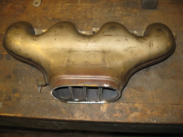
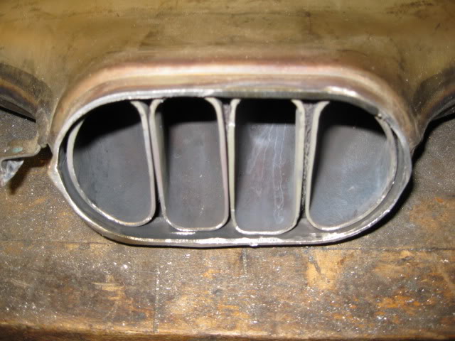
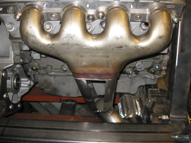
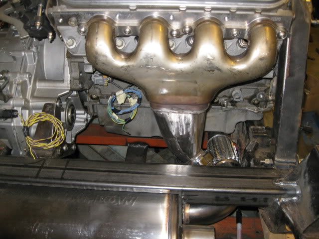
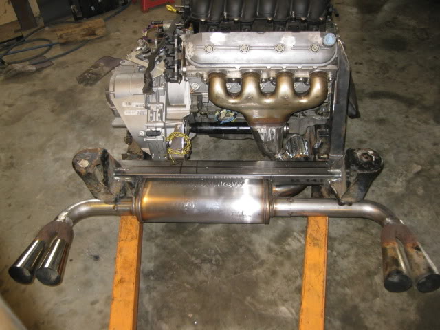
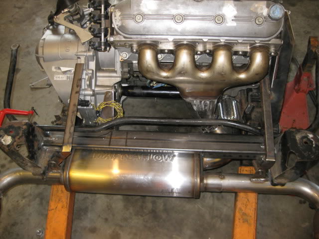
On to the exhaust... Everything is fabricated from stainless steel except a small portion of the factory fiero megaphone tips.
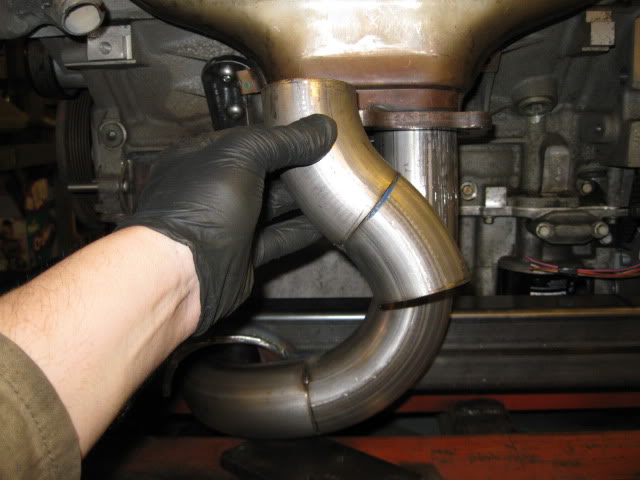
The collector portion is going to take quite a bit of work to form the oval transition to the 2 1/2" diameter.
Gotta love hacking up perfectly good manifolds:
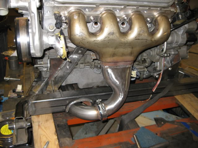
Test fitting the sections:
Template for the triangles:
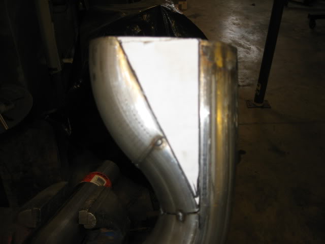
I took some of the stainless 16ga exhaust tubing, flattened it and sheared it to make the triangles and then tacked them in place:
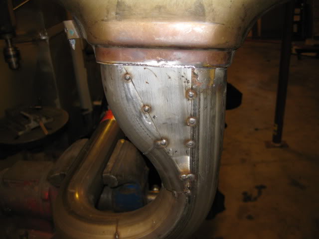
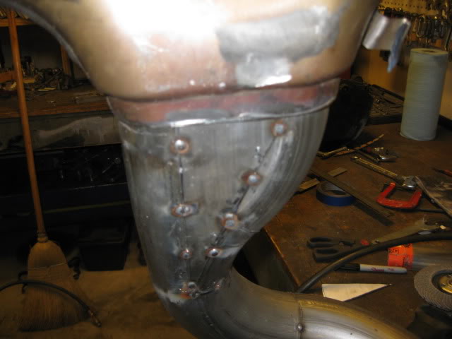
Now the front side just needs to be fully welded and smoothed:
In case you are wondering why I didn't use the factory bolt on flanges... mainly because the other half of the flanges cost $74 + the cost of the copper gaskets ($20) and the only aftermarket flanges available are mild steel. I want a 100% stainless exhaust and removing the flanges will save some weight and clean up the overall look.
Here are the parts for the rear most portion of the exhaust:
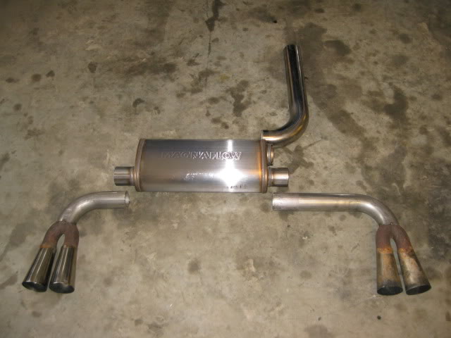
Yes, I know the stock fiero tips are not stainless steel and probably a restriction... but I use them on all my personal swaps, so they are staying.
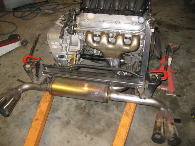
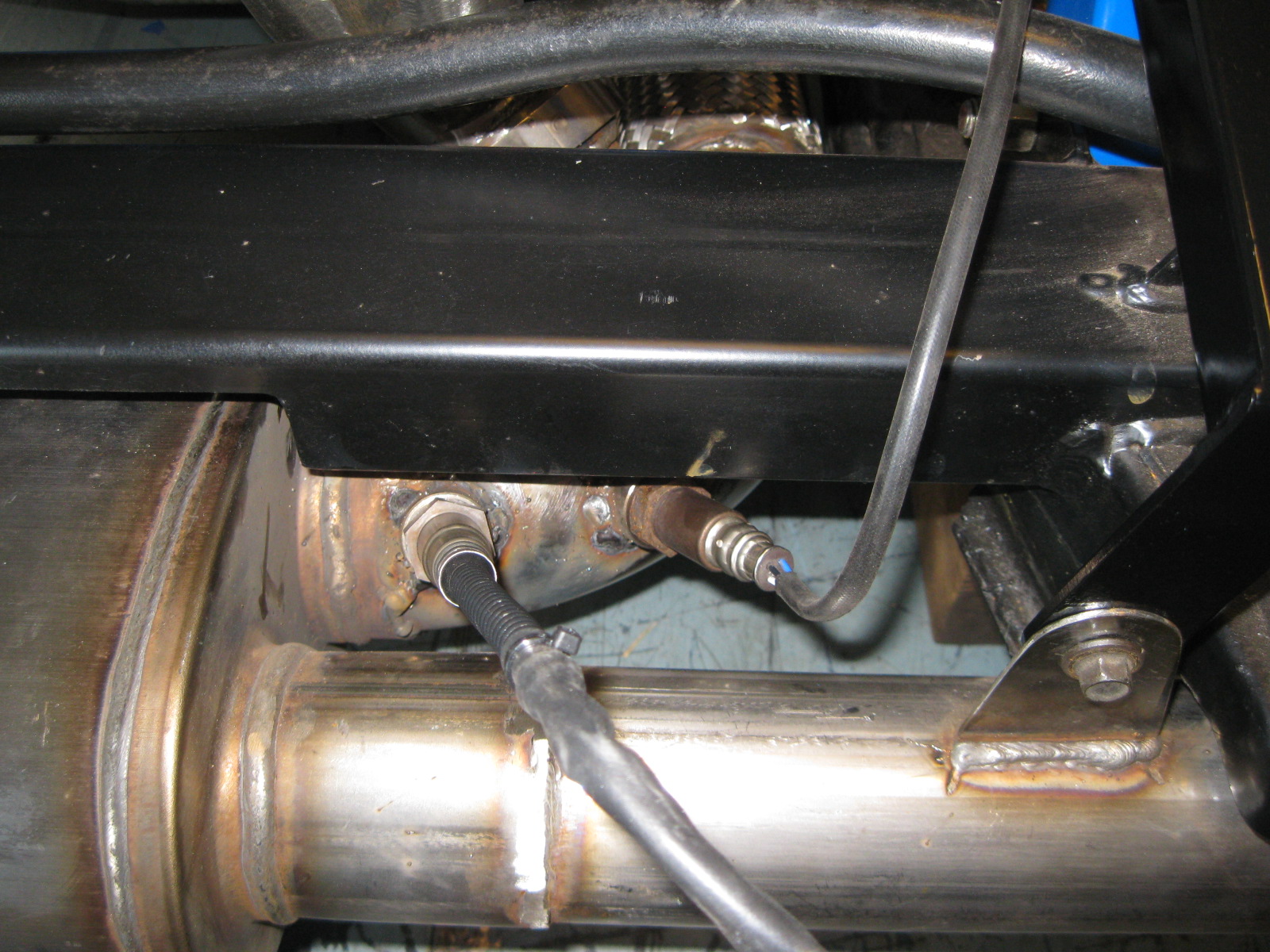
The cradle needed some slight tweaks. The Magnaflow muffler is thicker than the Flowtech Afterburner I usually use, so I needed to clearance the rear cross-member slightly so I could raise it up more.
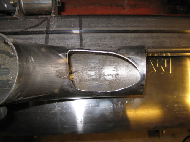
In addition to the rear cross-member, the factory exhaust notches in the cradle needed to be modified slightly. They were shortened about 3/8" and reshaped to better clear my exhaust pipes. This modification allows the Magnaflow muffler to fit without any modifications to the stock trunk. In this pic the bottom portion has already been cut back and the marker outline shows the amount to be removed:
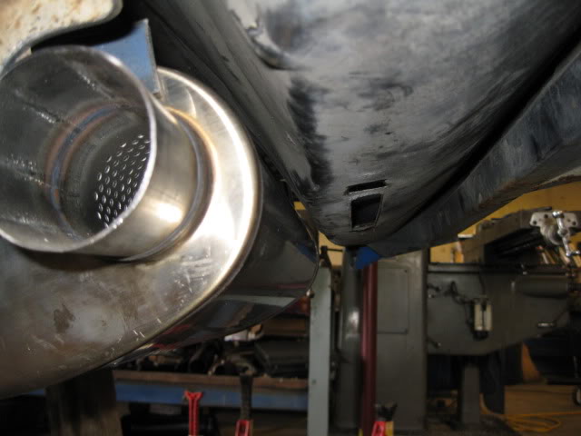
The last modification was to the lower lip of the passenger cradle rail. The 2 1/2" exhaust runs within 3/8" of it and it needs more room for the enlargement to 3". I had kicked around trimming it for the entire length, but chose to just do the portion that is behind the oil pan (seam will be fully welded).
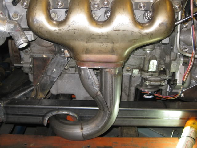
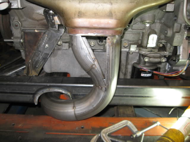
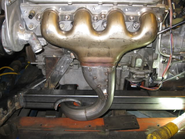
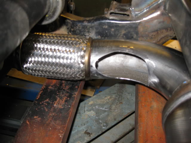
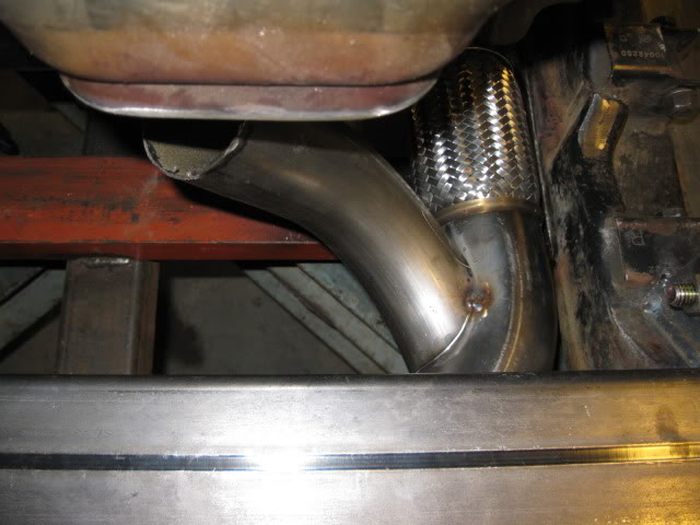
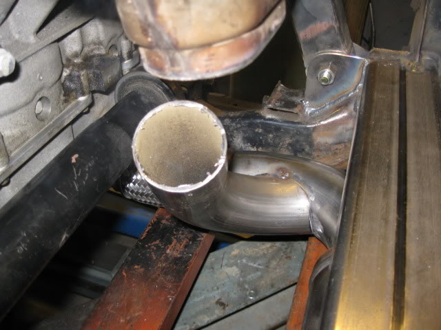
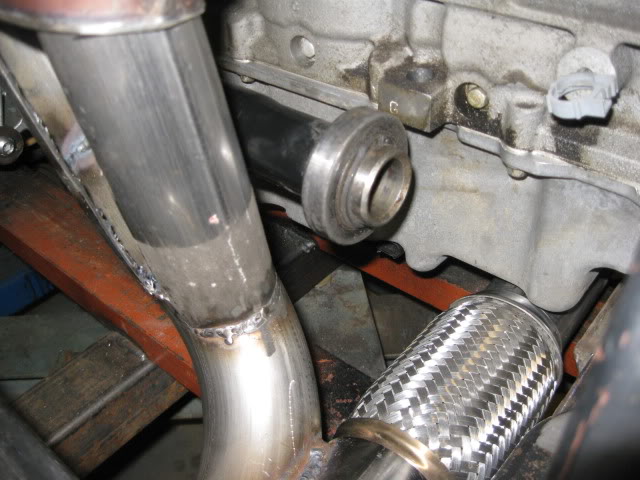
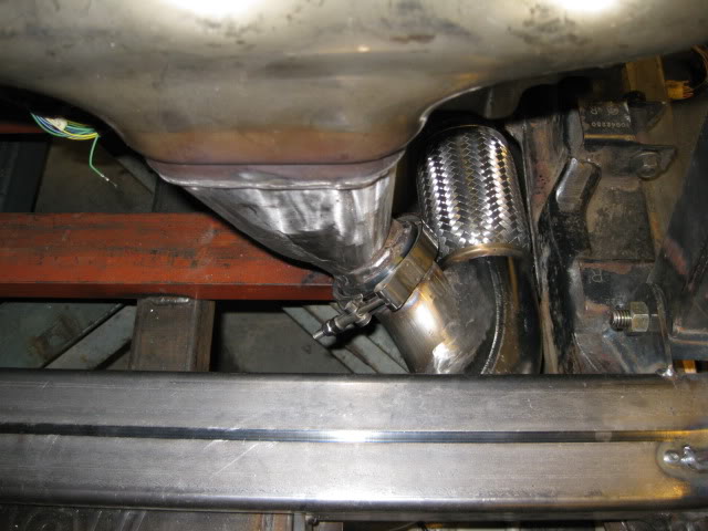
Here are a couple more progress pics to show how the exhaust will be routing:
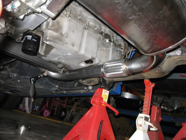
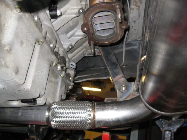
It is 2 1/2" coming from under the oil pan, into a flex coupler then to 3" mandrel bend into the muffler. The rear bank will come down and merge into the 3" section prior to the muffler.
Tacked the muffler to the cradle in its proper position so I can fabricate the rear manifold tube on the bench vs. under the car.
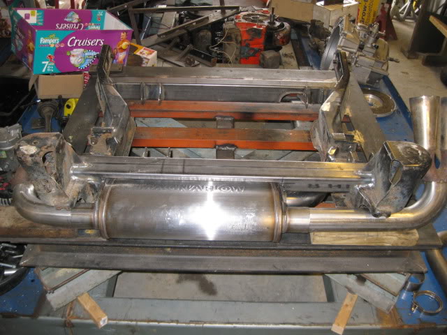
After it was tacked, I put the cradle back in the chassis to confirm the placement clears the truck... by about 3/8":
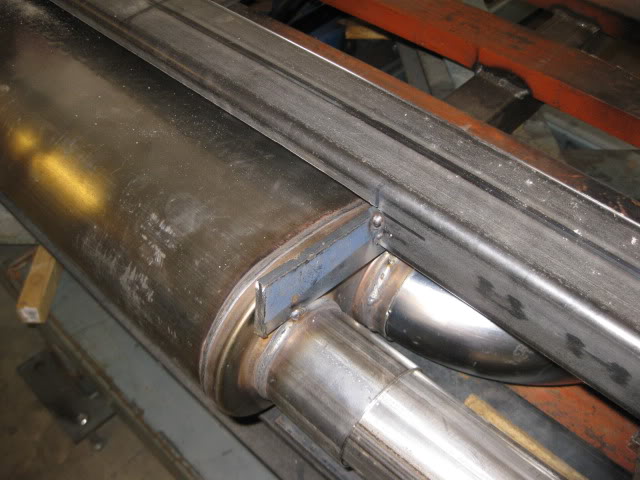
Then it was back on the table and ended up with this merge section:
Made some progress on the rear exhaust...
There will be two ring clamps that connect the exhaust to the manifolds. Here is the one in front:
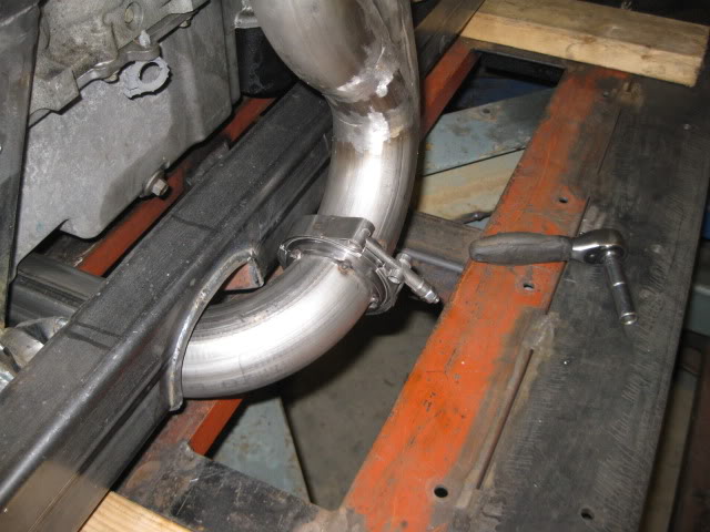
And the one in the rear will go here:
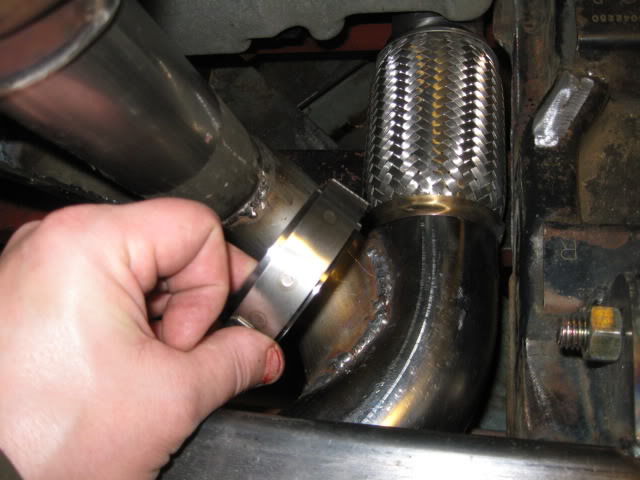
Installed the MLS exhaust gaskets to ensure proper manifold placement, installed the 2nd and last v-band and started to clean up the welds. The end product will be 3 pieces: two manifolds/downpipes and a single Y pipe/muffler/tail pipe section.
Slid the engine/tranny/cradle back under the car and finish welding the flexible section, the 3" section going into the muffler and the two tail pipes.
Put the engine/trans/cradle back in the chassis (my old SBC chassis since it was empty) to locate and tack weld the rest of the exhaust system:
Then took it back out again to work on the exhaust hangers:
Installed the sway bar just to make sure the new hangers will clear the motion of the sway bar:
The idea is for the exhaust to rock back and forth with the engine (engine will not move much, but it will move), so I wanted the exhaust hangers to attach to the drivetrain and then cantilever out over the sway bar to support the muffler and tail pipe section. The hangers needed to allow for a slight amount of movement to the rear and to the driver side for thermal expansion, but still solidly hold the muffler/tail pipes.
I decided to make some stainless steel hangers from some of the left over exhaust pipe (16ga). Flatten it, cut it to shape and then weld it to the exhaust tubes. The 16ga material should allow some thermal expansion movement.
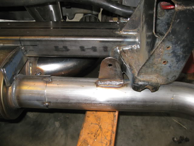
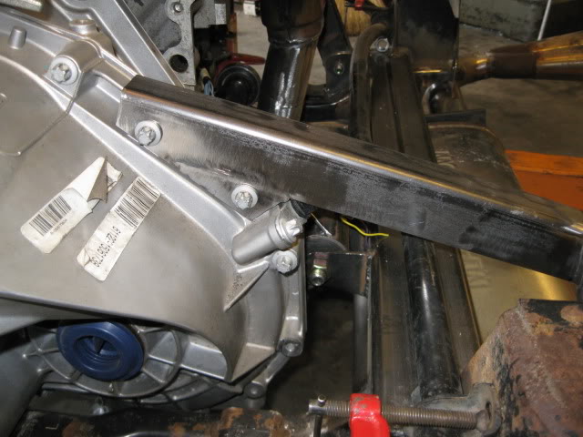
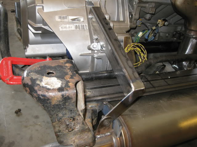
Then it was a matter of making the long brackets that would connect to the drive train. For the tranny side, the transmission case bolts around the differential were in the right general location, so I used them. The material is the "L" section I removed from the rear crossmember for muffler clearance. I did have to weld on a bracket to pickup the 2nd differential bolt and weld on the end piece that will attach to the stainless tabs on the exhaust. Using an angle section on this side will allow the bracket to rotate slightly to accommodate some expansion between the two rear hangers.
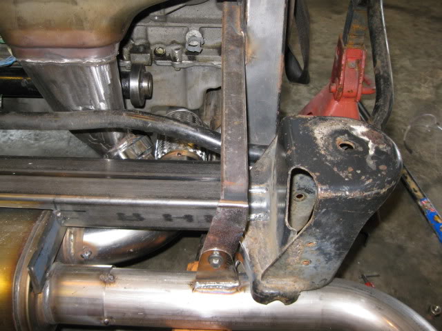
The passenger side one is just some 1x1 square tubing welded to the rear engine mount bracket and the tab welded to the end to connect to the stainless steel tab.
Now I can break the tack welds holding the muffler in place and remove the exhaust for the finish welding. The lower section of the exhaust is held in place with 4 bolts. 1 bolt on each V-band clamps and the 2 bolts at the tail pipe hangers... it will be rather quick to remove this in the future...
The collector portion is going to take quite a bit of work to form the oval transition to the 2 1/2" diameter.
Gotta love hacking up perfectly good manifolds:
Test fitting the sections:
Template for the triangles:
I took some of the stainless 16ga exhaust tubing, flattened it and sheared it to make the triangles and then tacked them in place:
Now the front side just needs to be fully welded and smoothed:
In case you are wondering why I didn't use the factory bolt on flanges... mainly because the other half of the flanges cost $74 + the cost of the copper gaskets ($20) and the only aftermarket flanges available are mild steel. I want a 100% stainless exhaust and removing the flanges will save some weight and clean up the overall look.
Here are the parts for the rear most portion of the exhaust:
Yes, I know the stock fiero tips are not stainless steel and probably a restriction... but I use them on all my personal swaps, so they are staying.
The cradle needed some slight tweaks. The Magnaflow muffler is thicker than the Flowtech Afterburner I usually use, so I needed to clearance the rear cross-member slightly so I could raise it up more.
In addition to the rear cross-member, the factory exhaust notches in the cradle needed to be modified slightly. They were shortened about 3/8" and reshaped to better clear my exhaust pipes. This modification allows the Magnaflow muffler to fit without any modifications to the stock trunk. In this pic the bottom portion has already been cut back and the marker outline shows the amount to be removed:
The last modification was to the lower lip of the passenger cradle rail. The 2 1/2" exhaust runs within 3/8" of it and it needs more room for the enlargement to 3". I had kicked around trimming it for the entire length, but chose to just do the portion that is behind the oil pan (seam will be fully welded).
Here are a couple more progress pics to show how the exhaust will be routing:
It is 2 1/2" coming from under the oil pan, into a flex coupler then to 3" mandrel bend into the muffler. The rear bank will come down and merge into the 3" section prior to the muffler.
Tacked the muffler to the cradle in its proper position so I can fabricate the rear manifold tube on the bench vs. under the car.
After it was tacked, I put the cradle back in the chassis to confirm the placement clears the truck... by about 3/8":
Then it was back on the table and ended up with this merge section:
Made some progress on the rear exhaust...
There will be two ring clamps that connect the exhaust to the manifolds. Here is the one in front:
And the one in the rear will go here:
Installed the MLS exhaust gaskets to ensure proper manifold placement, installed the 2nd and last v-band and started to clean up the welds. The end product will be 3 pieces: two manifolds/downpipes and a single Y pipe/muffler/tail pipe section.
Slid the engine/tranny/cradle back under the car and finish welding the flexible section, the 3" section going into the muffler and the two tail pipes.
Put the engine/trans/cradle back in the chassis (my old SBC chassis since it was empty) to locate and tack weld the rest of the exhaust system:
Then took it back out again to work on the exhaust hangers:
Installed the sway bar just to make sure the new hangers will clear the motion of the sway bar:
The idea is for the exhaust to rock back and forth with the engine (engine will not move much, but it will move), so I wanted the exhaust hangers to attach to the drivetrain and then cantilever out over the sway bar to support the muffler and tail pipe section. The hangers needed to allow for a slight amount of movement to the rear and to the driver side for thermal expansion, but still solidly hold the muffler/tail pipes.
I decided to make some stainless steel hangers from some of the left over exhaust pipe (16ga). Flatten it, cut it to shape and then weld it to the exhaust tubes. The 16ga material should allow some thermal expansion movement.
Then it was a matter of making the long brackets that would connect to the drive train. For the tranny side, the transmission case bolts around the differential were in the right general location, so I used them. The material is the "L" section I removed from the rear crossmember for muffler clearance. I did have to weld on a bracket to pickup the 2nd differential bolt and weld on the end piece that will attach to the stainless tabs on the exhaust. Using an angle section on this side will allow the bracket to rotate slightly to accommodate some expansion between the two rear hangers.
The passenger side one is just some 1x1 square tubing welded to the rear engine mount bracket and the tab welded to the end to connect to the stainless steel tab.
Now I can break the tack welds holding the muffler in place and remove the exhaust for the finish welding. The lower section of the exhaust is held in place with 4 bolts. 1 bolt on each V-band clamps and the 2 bolts at the tail pipe hangers... it will be rather quick to remove this in the future...
Last edited by fieroguru; 09-29-2012 at 05:43 PM.

The following users liked this post:
Ls7colorado (04-18-2022)