
Big engine in small car take 734985: LS1 Miata plus frivolous insanity.
 04-05-2013, 02:16 PM
#1
Teching In
Thread Starter

Join Date: Jul 2012
Posts: 21
Likes: 0
Received 0 Likes
on
0 Posts
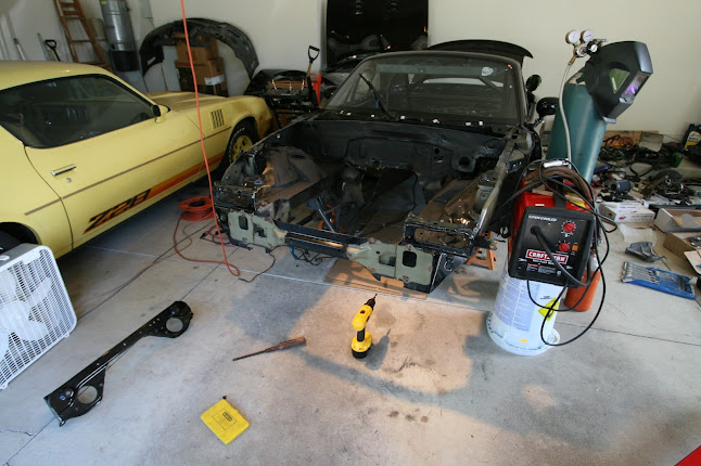
I snatched a turbo Miata after a careless deer dashed in front of my beloved WRX, causing the annihilation of both parties. The Miata was fun, and I made it more fun, but in the end, I was driving a car that somebody else built......and that just wasn't for me. After blowing the notoriously weak five-speed at an auto-x, I sold the 1.8 and all of the turbo stuff, and began to prep the chassis for bigger and better things. The project began in the summer of 2012 and the car should be drivable again this summer. The car is a 1994 Mazda Miata R-package, and I'm swapping in an LS1 and T56 from a 2004 GTO.
I've been documenting the project closely on my blog: http://www.cgbagne.com/theturtlebuild/
Posts in this thread are copied and pasted directly from there.
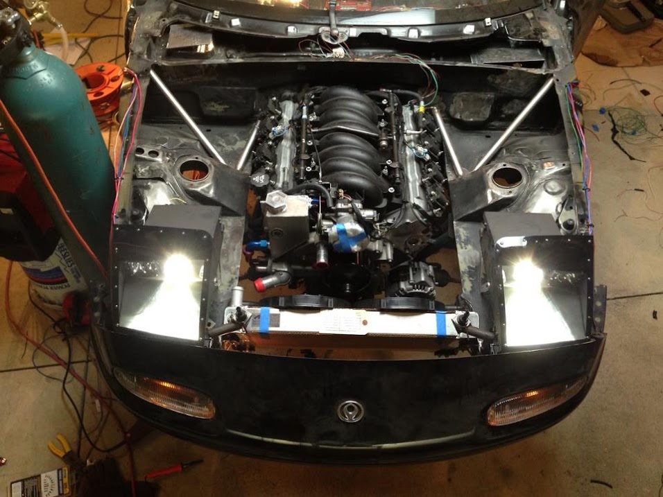
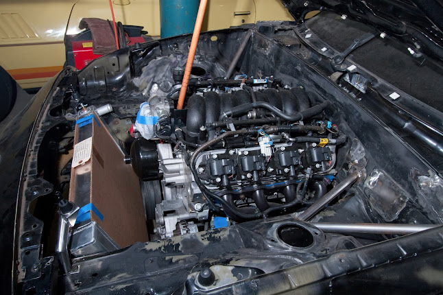
This is roughly where the car sits right now:
I've been documenting the project closely on my blog: http://www.cgbagne.com/theturtlebuild/
Posts in this thread are copied and pasted directly from there.
This is roughly where the car sits right now:
Last edited by 573; 04-06-2013 at 10:37 AM.
 04-05-2013, 02:18 PM
#2
Teching In
Thread Starter
Join Date: Jul 2012
Posts: 21
Likes: 0
Received 0 Likes
on
0 Posts
July 23, 2012:
This is about where the car sat before the start of this V8 build. It had a modest turbo setup and was pretty well gutted. When I bought the car, it had an even more modest turbo setup, wasn't gutted, and didn't have the awesome headlights. My build thread on miataturbo.net loosely chronicles the progression of the car from the point at which I bought it up until present. There's quite a bit of info in there on my headlights, as well. http://www.miataturbo.net/build-thre...han-last-61859


This is about where the car sat before the start of this V8 build. It had a modest turbo setup and was pretty well gutted. When I bought the car, it had an even more modest turbo setup, wasn't gutted, and didn't have the awesome headlights. My build thread on miataturbo.net loosely chronicles the progression of the car from the point at which I bought it up until present. There's quite a bit of info in there on my headlights, as well. http://www.miataturbo.net/build-thre...han-last-61859
Last edited by 573; 04-05-2013 at 03:54 PM.
04-05-2013, 02:20 PM
#3
Teching In
Thread Starter
Join Date: Jul 2012
Posts: 21
Likes: 0
Received 0 Likes
on
0 Posts
August 9, 2012:
The first step was to remove all of the things. Although that sounds vague, it aptly describes what I did. This post only shows you the beginning.
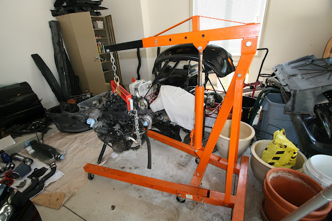
First, the engine and transmission were removed. I had never pulled an engine or a transmission prior to this point, and conveniently, it was properly simple. The key is to triple check that everything is unbolted and disconnected. Having a load leveler helps(mine was from Harbor Freight), and so does periodically checking clearances as you're lifting out the drivetrain. I wasn't worried about scratching the paint because I knew that I'd have to repaint the bay, but I was still quite careful.

Removing the bumper provided more room to work, and having it out of the way was nice. The fenders were removed as well to protect them and because I planned to stitch weld beneath them.

As you can see, the garage was a huge mess at this point--car parts and other junk strewn about. Thanks to craigslist, forum classifieds, and family, I got much of the stuff cleared out and ended up with some more money for my fun fund.
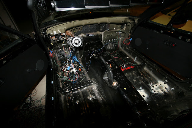
Keeping the OEM harness didn't make sense since the car is stripped. I marked and separated what I wanted to keep and hastily removed the rest. This is where a wiring schematic of the vehicle really comes in handy. I saved most of the wires coming off of the steering column, the exterior lighting wires were labeled and set aside, and the wires going to the rear of the car (lighting, fuel pump, fuel level sensor, and main power supply) were coiled up and set aside. The car will go back together with the LS1 engine harness, aftermarket gauges, aftermarket fuse blocks and relays, and all of that will be tied together by myself. I'm doing this for weight reduction and simplicity.

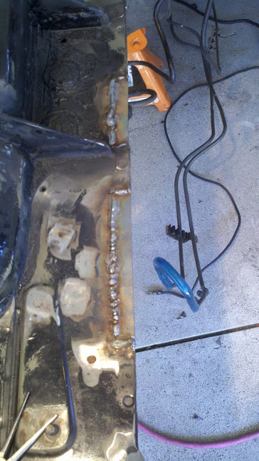
Further disassembly. Pardon the lousy cellphone photo. They'll make their way in here from time to time. :/

The state of the interior:
The first step was to remove all of the things. Although that sounds vague, it aptly describes what I did. This post only shows you the beginning.
First, the engine and transmission were removed. I had never pulled an engine or a transmission prior to this point, and conveniently, it was properly simple. The key is to triple check that everything is unbolted and disconnected. Having a load leveler helps(mine was from Harbor Freight), and so does periodically checking clearances as you're lifting out the drivetrain. I wasn't worried about scratching the paint because I knew that I'd have to repaint the bay, but I was still quite careful.
Removing the bumper provided more room to work, and having it out of the way was nice. The fenders were removed as well to protect them and because I planned to stitch weld beneath them.
As you can see, the garage was a huge mess at this point--car parts and other junk strewn about. Thanks to craigslist, forum classifieds, and family, I got much of the stuff cleared out and ended up with some more money for my fun fund.
Keeping the OEM harness didn't make sense since the car is stripped. I marked and separated what I wanted to keep and hastily removed the rest. This is where a wiring schematic of the vehicle really comes in handy. I saved most of the wires coming off of the steering column, the exterior lighting wires were labeled and set aside, and the wires going to the rear of the car (lighting, fuel pump, fuel level sensor, and main power supply) were coiled up and set aside. The car will go back together with the LS1 engine harness, aftermarket gauges, aftermarket fuse blocks and relays, and all of that will be tied together by myself. I'm doing this for weight reduction and simplicity.
Further disassembly. Pardon the lousy cellphone photo. They'll make their way in here from time to time. :/
The state of the interior:
Last edited by 573; 04-05-2013 at 03:53 PM.
04-05-2013, 02:23 PM
#4
Teching In
Thread Starter
Join Date: Jul 2012
Posts: 21
Likes: 0
Received 0 Likes
on
0 Posts
August 12, 2012
I drove to Cleveland Pick-A-Part the other day to pick up an LS1 and T56 from a 2004 GTO. The engine has 47k miles and came with a warranty. I'm impressed with Pick-A-Part. They thoroughly inspected my engine before sellin it. That inspection included a compression test, measurement of oil pressure, and measurement of vacuum. They also took a video of the engine running. The engine and trans looked immaculate when I got them. There was no grease or grime to be found. I took a peak under a valve cover as well. It looked as though they had taken everything apart, steam cleaned all of the components, and reassembled them with lubricant. The valvetrain looked brand new. You can certainly find parts for less on craigslist and so on, but quality salvage places like Cleveland Pick-A-Part are the way to go if you're not looking to gamble with your money. I know exactly what I bought and I know that it works. That feels good.
Removing the parts from the trailer was interesting and involved my dad creeping forward in his van while the pallet was tied to my Subaru. The unloading went perfectly.

Oh my!

A quick test fit.

The big parts that I still need now are the V8R swap kit(ordered) and a Getrag rear differential.
I drove to Cleveland Pick-A-Part the other day to pick up an LS1 and T56 from a 2004 GTO. The engine has 47k miles and came with a warranty. I'm impressed with Pick-A-Part. They thoroughly inspected my engine before sellin it. That inspection included a compression test, measurement of oil pressure, and measurement of vacuum. They also took a video of the engine running. The engine and trans looked immaculate when I got them. There was no grease or grime to be found. I took a peak under a valve cover as well. It looked as though they had taken everything apart, steam cleaned all of the components, and reassembled them with lubricant. The valvetrain looked brand new. You can certainly find parts for less on craigslist and so on, but quality salvage places like Cleveland Pick-A-Part are the way to go if you're not looking to gamble with your money. I know exactly what I bought and I know that it works. That feels good.
Removing the parts from the trailer was interesting and involved my dad creeping forward in his van while the pallet was tied to my Subaru. The unloading went perfectly.
Oh my!
A quick test fit.
The big parts that I still need now are the V8R swap kit(ordered) and a Getrag rear differential.
Last edited by 573; 04-05-2013 at 03:29 PM.
04-05-2013, 02:27 PM
#5
Teching In
Thread Starter
Join Date: Jul 2012
Posts: 21
Likes: 0
Received 0 Likes
on
0 Posts
August 24, 2012:
Good design is an uncompromising blend of form and function. Why sacrifice one when you can have both, particularly if you can make them compliment one another. I had tons of holes in the firewall that weren't going to be used. They were ugly and they'd have let fire through. What's the point of a firewall that doesn't effectively block fire? Idk, but now they're plugged so no fire will get through and an eyesore is gone. The strut tops were also really quite ugly. That's unacceptable. I triangulated them to the frame rails. That's good, and looks really good.
If you're thinking about shaving your bay...stop. Seriously, cut it out. Save yourself the agony. The process requires tons of mindless labor and will leave you feeling broken in the end. It's a lesson on how much manual labor sucks, and makes me glad that I'm going to school. But then again, I got most of this work done in a single day. Who knows, maybe I won't be so bitter towards the process later as I am now--just waking up with a sore back. 22 year olds aren't supposed to wake up with sore backs. I'm normally far too youthful and robust for that. If you're old, shaving your bay will cause you to become an alcoholic.
Anyway, check it!
I started by cutting out the sections of frame rail that were raised for the stock fuel, return, and evap lines. I welded new metal in place.
The previous owner cut a section out of the frame rail to clear the turbo. I patched that with some new metal.

I started on the strut tops after I got the frame rails cleaned up.

I made templates out of paper, cut metal to the right shape, twisted the metal to follow the controur, did a little bit more trimming, and tacked it in place. The center segment is entirely flat, but the sides required some light bending with my design.

The factory gussets weren't exactly symmetrical from the factory so I had to weld in a wedge of metal to make both sides level. Now the gusset meets up with my plate.

Then weld.
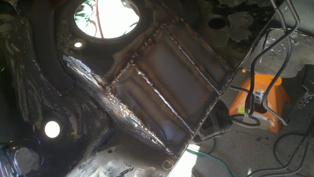

This is what they looked like when they were nearly done. I'm certainly not the first to box the strut tops on a Miata, but as far as I know, I'm the first to go about it this way. Mine look the best...and are the strongest. Winrar!

I did the grinding with 60 and 120 grit flapper disks.

These will look amazing with the tiniest amount of filler and some paint.
Then plugged the holes in the firewall.
Because heaters are for those who do not have jackets:

Because AC is for men who carry handbags:

I also got rid of the two big holes that scary masses of factory tentacles run through. Welding in those cramped areas with poor lighting and no visibility was kind of tricky. My welds looks pretty lousy, but this isn't structural.

This is how the bay looked when I went to bed. All I have left is the hole in the passenger side frame rail.

In other news, my Flyin' Miata v8 sway bar came in yesterday. It looks good. My Sanderson ceramic coated block hugger headers came in a few days ago. They look good. I also picked up a Getrag differential from a local salvage place. 3.23, so second gear may serve a purpose if I have race tires on there, 4k miles, and I got it for a good price($250). Hooray!
Good design is an uncompromising blend of form and function. Why sacrifice one when you can have both, particularly if you can make them compliment one another. I had tons of holes in the firewall that weren't going to be used. They were ugly and they'd have let fire through. What's the point of a firewall that doesn't effectively block fire? Idk, but now they're plugged so no fire will get through and an eyesore is gone. The strut tops were also really quite ugly. That's unacceptable. I triangulated them to the frame rails. That's good, and looks really good.
If you're thinking about shaving your bay...stop. Seriously, cut it out. Save yourself the agony. The process requires tons of mindless labor and will leave you feeling broken in the end. It's a lesson on how much manual labor sucks, and makes me glad that I'm going to school. But then again, I got most of this work done in a single day. Who knows, maybe I won't be so bitter towards the process later as I am now--just waking up with a sore back. 22 year olds aren't supposed to wake up with sore backs. I'm normally far too youthful and robust for that. If you're old, shaving your bay will cause you to become an alcoholic.
Anyway, check it!
I started by cutting out the sections of frame rail that were raised for the stock fuel, return, and evap lines. I welded new metal in place.
The previous owner cut a section out of the frame rail to clear the turbo. I patched that with some new metal.
I started on the strut tops after I got the frame rails cleaned up.
I made templates out of paper, cut metal to the right shape, twisted the metal to follow the controur, did a little bit more trimming, and tacked it in place. The center segment is entirely flat, but the sides required some light bending with my design.
The factory gussets weren't exactly symmetrical from the factory so I had to weld in a wedge of metal to make both sides level. Now the gusset meets up with my plate.
Then weld.
This is what they looked like when they were nearly done. I'm certainly not the first to box the strut tops on a Miata, but as far as I know, I'm the first to go about it this way. Mine look the best...and are the strongest. Winrar!
I did the grinding with 60 and 120 grit flapper disks.
These will look amazing with the tiniest amount of filler and some paint.
Then plugged the holes in the firewall.
Because heaters are for those who do not have jackets:
Because AC is for men who carry handbags:
I also got rid of the two big holes that scary masses of factory tentacles run through. Welding in those cramped areas with poor lighting and no visibility was kind of tricky. My welds looks pretty lousy, but this isn't structural.
This is how the bay looked when I went to bed. All I have left is the hole in the passenger side frame rail.
In other news, my Flyin' Miata v8 sway bar came in yesterday. It looks good. My Sanderson ceramic coated block hugger headers came in a few days ago. They look good. I also picked up a Getrag differential from a local salvage place. 3.23, so second gear may serve a purpose if I have race tires on there, 4k miles, and I got it for a good price($250). Hooray!
Last edited by 573; 04-05-2013 at 03:35 PM.
04-05-2013, 02:30 PM
#6
Teching In
Thread Starter
Join Date: Jul 2012
Posts: 21
Likes: 0
Received 0 Likes
on
0 Posts
August 26, 2012:
This build is going to be moving slowly for the next couple of months. The only work that will be done is that which I can fit in if I find myself home for a weekend. The good news is that I will have all of the parts together by the time my lengthy winter break starts. During that break, I am going to have no life and I am going to finish this thing.
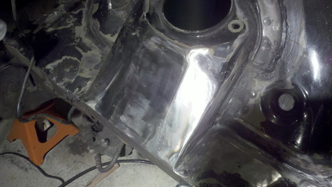
In the mean time, the car has been prepared for dormancy. I covered all of the bare metal with three different types of spray paint that I had on hand and cleaned all of the steel dust off of the paint. It's ready to sit, but hopefully won't have to sit for too long. I'm hoping that I can get the transmission tunnel finished and the engine bay painted before the weather turns cold. That may be a lofty goal for sporadic weekend labor, but I'll do what I can to make it happen.
Pre-body filler and it looks pretty good.


These are going to look excellant once I touch them up with a little bit of filler.


Not much evidence of this thing having heat in a previous life.

I also patched up the corners of the engine bay.


The car hasn't been this clean in weeks.
This build is going to be moving slowly for the next couple of months. The only work that will be done is that which I can fit in if I find myself home for a weekend. The good news is that I will have all of the parts together by the time my lengthy winter break starts. During that break, I am going to have no life and I am going to finish this thing.
In the mean time, the car has been prepared for dormancy. I covered all of the bare metal with three different types of spray paint that I had on hand and cleaned all of the steel dust off of the paint. It's ready to sit, but hopefully won't have to sit for too long. I'm hoping that I can get the transmission tunnel finished and the engine bay painted before the weather turns cold. That may be a lofty goal for sporadic weekend labor, but I'll do what I can to make it happen.
Pre-body filler and it looks pretty good.
These are going to look excellant once I touch them up with a little bit of filler.
Not much evidence of this thing having heat in a previous life.
I also patched up the corners of the engine bay.
The car hasn't been this clean in weeks.
Last edited by 573; 04-05-2013 at 03:36 PM.
04-05-2013, 02:31 PM
#7
Teching In
Thread Starter
Join Date: Jul 2012
Posts: 21
Likes: 0
Received 0 Likes
on
0 Posts
August 31, 2012:
Here's a post that isn't particularly substantive to hold over my hardcore readers until I have time to pick up a wrench again.
I ordered these wheels before I blew the transmission and they came in the week after the car went down. I also have 225 Hankook RS3's--same story. They're bronze 15x9 6ul's from 949Racing. +36 offset, 13.6 pounds each. They'll look great on my car and they'll provide me with much more grip than the old setup(stockers with rt615's).
Trending Topics
04-05-2013, 02:33 PM
#8
Teching In
Thread Starter
Join Date: Jul 2012
Posts: 21
Likes: 0
Received 0 Likes
on
0 Posts
September 16, 2012:
After much waiting, my swap kit is here. I could talk about it, or I could post photos. I prefer to do the latter.
Boxes of V8R and other parts.

One of the frame rail braces.

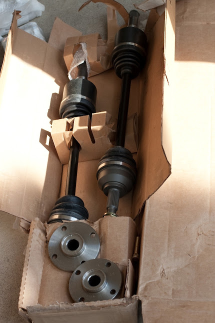
Heavy duty axles and hubs.
The hubs and ARP wheel studs.

Some nice wheel bearings for those fancy hubs

A larger Wilwood master cylinder to appropriately serve the larger T56 slave cylinder.

Transmission crossmember.

Getrag diff mount.

Not part of the swap kit, but this is some fancy frame rail sealer that I sprayed into the strut tops, which I boxed, so that the insides won't rust. Eastwood makes good stuff, so I should be in good shape.

After much waiting, my swap kit is here. I could talk about it, or I could post photos. I prefer to do the latter.
Boxes of V8R and other parts.
One of the frame rail braces.
Heavy duty axles and hubs.
The hubs and ARP wheel studs.
Some nice wheel bearings for those fancy hubs
A larger Wilwood master cylinder to appropriately serve the larger T56 slave cylinder.
Transmission crossmember.
Getrag diff mount.
Not part of the swap kit, but this is some fancy frame rail sealer that I sprayed into the strut tops, which I boxed, so that the insides won't rust. Eastwood makes good stuff, so I should be in good shape.
Last edited by 573; 04-05-2013 at 03:32 PM.
04-05-2013, 02:35 PM
#9
Teching In
Thread Starter
Join Date: Jul 2012
Posts: 21
Likes: 0
Received 0 Likes
on
0 Posts
September 16, 2012:
I borrowed another engine puller from another guy(thanks Carlos) this morning and the engine went in not too long after. Cutting the front off helped immensely and allowed the engine and trans to go in together. After I installed the crossmember, it was a matter of getting the slightly cumbersome engine and transmission assembly lined up and bolted in. Obviously, this isn't the final installation of the engine. It's in so that I can rebuild the transmission tunnel with proper clearance for the bell housing. I'll also figure out where the wiring and fuel lines will need to be run so that I can install those later on, when the engine is out, and actually do a good job of it. The V8Roadsters frame rails and transmission crossmember still need to be bolted in. I'm waiting on that, or at least on the crossmember, until I get the rear end in so that I can ensure that everything is straight and properly aligned.
Engine and trans, suspended by seatbelt webbing.

The crossmember is in, and part of the front fell off. Good start.
V8R crossmember.

A box of seatbelt webbing, courtesy of the guy who I borrowed the hoist from. It's convenient for holding the engine and trans up, particularly since my engine is missing one of the lift hooks.

My angle grinder couldn't cut deep enough to remove the front. The front had to come off, so Pat came with a sawzall and did some work. He also helped me get the engine lined up and bolted in. Thanks Pat.

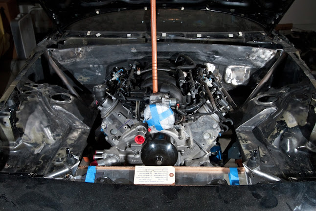
It's in. Hooray.

Yep, still there.
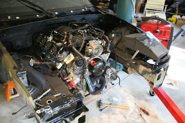

Oh yeah, I still don't have the right oil pan. I removed the GTO oil pan, which doesn't clear the crossmember, and used the gasket to hold some plastic tarp material in place. Good enough to keep crud out until I get my oil pan situation straightened out.

I borrowed another engine puller from another guy(thanks Carlos) this morning and the engine went in not too long after. Cutting the front off helped immensely and allowed the engine and trans to go in together. After I installed the crossmember, it was a matter of getting the slightly cumbersome engine and transmission assembly lined up and bolted in. Obviously, this isn't the final installation of the engine. It's in so that I can rebuild the transmission tunnel with proper clearance for the bell housing. I'll also figure out where the wiring and fuel lines will need to be run so that I can install those later on, when the engine is out, and actually do a good job of it. The V8Roadsters frame rails and transmission crossmember still need to be bolted in. I'm waiting on that, or at least on the crossmember, until I get the rear end in so that I can ensure that everything is straight and properly aligned.
Engine and trans, suspended by seatbelt webbing.
The crossmember is in, and part of the front fell off. Good start.
V8R crossmember.
A box of seatbelt webbing, courtesy of the guy who I borrowed the hoist from. It's convenient for holding the engine and trans up, particularly since my engine is missing one of the lift hooks.
My angle grinder couldn't cut deep enough to remove the front. The front had to come off, so Pat came with a sawzall and did some work. He also helped me get the engine lined up and bolted in. Thanks Pat.
It's in. Hooray.
Yep, still there.
Oh yeah, I still don't have the right oil pan. I removed the GTO oil pan, which doesn't clear the crossmember, and used the gasket to hold some plastic tarp material in place. Good enough to keep crud out until I get my oil pan situation straightened out.
Last edited by 573; 04-05-2013 at 03:33 PM.
04-05-2013, 02:37 PM
#10
Teching In
Thread Starter
Join Date: Jul 2012
Posts: 21
Likes: 0
Received 0 Likes
on
0 Posts
September 17, 2012:
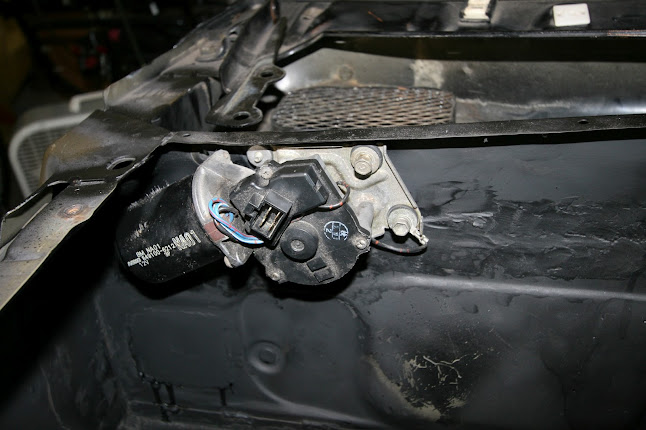
The wiper motor was like a large malignant tumor on my otherwise healthy firewall. That, and I knew a better place for it. A place that would put a little bit of weight a little bit further back. I needed to operate...stat.
Relocating the wiper motor involved cutting out the section of firewall that the motor mounted to and relocating it to the bottom of the cowl. That way, the motor itself is safely tucked away in the interior, and the arm goes into the cowl area so that the arm can still actuate the rod, which actuates the much larger arm that cleans the window. I traced the mounting plate onto the cowl, where I wanted it. I cut that area out and spot welded the motor mounting plate in. I also spot welded a patch into the gaping hole that I created in the firewall. The actuator rod had to be cut, sectioned, and welded so that both ends would properly meet up to the motor and wiper arm. Most of it is only held in with spot welds at this point. I'll finish this next time I'm home, and update with some new photos. In the end, it should look and function as though my new location was the factory location.
One concern is that this could be a potential ingress point for water. The motor shaft enters the cowl though a hole in an elevated portion of the motor mount plate. Gravity won't help water get in. The motor also has a rubber seal that seals against the area surrounding the shaft hole. That'll further prevent water from entering. The relocation negligibly changes the geometry of the wiper system. Components will be stressed no more than they were in the factory configuration. Adjustment of starting position and sweep can be carried out through unbolting the motor arm from the motor shaft and from unbolting the wiper arm from its pivot. Each can be individually adjusted via rotation until desirable operation is achieved.
The sight of motor makes me cringe!
So I evicted motor from its home.

Motor is still a vagrant, but has been reunited with its surface.

Wiper motor has a new home, and it's quite an upgrade. Motor should be pleased.

Firewall has been patched up and is on the road to recovery.

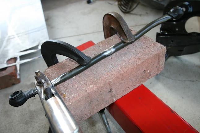
The actuator rod had to be shortened and twisted to work with this change. I measured, cut it with an angle grinder, cleaned the surfaces, welded it back together, and gave it a nice coat of black paint. The only criteria for the length is that it be such that the motor can make a full revolution without the wiper arm pivot hitting its hard stops.
Looks fine.

Edit: Here is another progress photo--a little further along now.

The wiper motor was like a large malignant tumor on my otherwise healthy firewall. That, and I knew a better place for it. A place that would put a little bit of weight a little bit further back. I needed to operate...stat.
Relocating the wiper motor involved cutting out the section of firewall that the motor mounted to and relocating it to the bottom of the cowl. That way, the motor itself is safely tucked away in the interior, and the arm goes into the cowl area so that the arm can still actuate the rod, which actuates the much larger arm that cleans the window. I traced the mounting plate onto the cowl, where I wanted it. I cut that area out and spot welded the motor mounting plate in. I also spot welded a patch into the gaping hole that I created in the firewall. The actuator rod had to be cut, sectioned, and welded so that both ends would properly meet up to the motor and wiper arm. Most of it is only held in with spot welds at this point. I'll finish this next time I'm home, and update with some new photos. In the end, it should look and function as though my new location was the factory location.
One concern is that this could be a potential ingress point for water. The motor shaft enters the cowl though a hole in an elevated portion of the motor mount plate. Gravity won't help water get in. The motor also has a rubber seal that seals against the area surrounding the shaft hole. That'll further prevent water from entering. The relocation negligibly changes the geometry of the wiper system. Components will be stressed no more than they were in the factory configuration. Adjustment of starting position and sweep can be carried out through unbolting the motor arm from the motor shaft and from unbolting the wiper arm from its pivot. Each can be individually adjusted via rotation until desirable operation is achieved.
The sight of motor makes me cringe!
So I evicted motor from its home.
Motor is still a vagrant, but has been reunited with its surface.
Wiper motor has a new home, and it's quite an upgrade. Motor should be pleased.
Firewall has been patched up and is on the road to recovery.
The actuator rod had to be shortened and twisted to work with this change. I measured, cut it with an angle grinder, cleaned the surfaces, welded it back together, and gave it a nice coat of black paint. The only criteria for the length is that it be such that the motor can make a full revolution without the wiper arm pivot hitting its hard stops.
Looks fine.
Edit: Here is another progress photo--a little further along now.
Last edited by 573; 04-05-2013 at 03:34 PM.
04-05-2013, 02:40 PM
#11
Teching In
Thread Starter
Join Date: Jul 2012
Posts: 21
Likes: 0
Received 0 Likes
on
0 Posts
September 30, 2012:
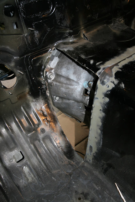
I added excessive clearance to the transmission tunnel with the BFH(big fu-riendly hammer). That ended up interfering with the movement of the gas pedal. Rather than breaking out the BFH again, and beating the offending part of the tunnel back in, I removed the afflicted portions of the tunnel on both sides. That way I'll have fresh metal that hasn't been fatigued by heat and lots of pounding. This was another home for the weekend sort of task, and still needs to be completed. The next step is to take out the engine and transmission so that I can finish the welding(both inside and out) and make it look pretty with the grinder. I'll do that once I bolt in the trans crossmember, figure out how I'm going to route the fuel lines and wires, and complete any other little tasks that require the engine to be in that it'll only have to come out once more before the final installation.
Metal peeled back to clear the larger t56 bell housing.

A quick cardboard mock-up to get a rough idea of the shape.

Substitute the cardboard for steel.

The piece has two bends in it to provide additional clearance for the go pedal and my feet.

I did the bending with my Harbor Freight metal brake. This thing is great for smaller tasks.

Tacked in.


Both sides are mostly welded in. This is the point where I ran out of time. Don't mind the ugly welds. They'll be ground down and made to look pretty since this car won't have carpet.

Most importantly...

Oh, and fun fact. These aren't the pedals that I'm going to be using.
I added excessive clearance to the transmission tunnel with the BFH(big fu-riendly hammer). That ended up interfering with the movement of the gas pedal. Rather than breaking out the BFH again, and beating the offending part of the tunnel back in, I removed the afflicted portions of the tunnel on both sides. That way I'll have fresh metal that hasn't been fatigued by heat and lots of pounding. This was another home for the weekend sort of task, and still needs to be completed. The next step is to take out the engine and transmission so that I can finish the welding(both inside and out) and make it look pretty with the grinder. I'll do that once I bolt in the trans crossmember, figure out how I'm going to route the fuel lines and wires, and complete any other little tasks that require the engine to be in that it'll only have to come out once more before the final installation.
Metal peeled back to clear the larger t56 bell housing.
A quick cardboard mock-up to get a rough idea of the shape.
Substitute the cardboard for steel.
The piece has two bends in it to provide additional clearance for the go pedal and my feet.
I did the bending with my Harbor Freight metal brake. This thing is great for smaller tasks.
Tacked in.
Both sides are mostly welded in. This is the point where I ran out of time. Don't mind the ugly welds. They'll be ground down and made to look pretty since this car won't have carpet.
Most importantly...
Oh, and fun fact. These aren't the pedals that I'm going to be using.
Last edited by 573; 04-05-2013 at 03:34 PM.
04-05-2013, 02:42 PM
#12
Teching In
Thread Starter
Join Date: Jul 2012
Posts: 21
Likes: 0
Received 0 Likes
on
0 Posts
October 21, 2012:
Today I:
-Drilled holes for the frame rail braces.
-Took measurements for the radiator, hole for wires, and fuel lines.
-Pulled the engine and trans, along with the subframe.
-Finished the transmission tunnel.
-Did more stitch welding around the tunnel.
-Filled more holes in the firewall.
-more welding and grinding than I care to do in a single day ever again.
The trans tunnel looks huge now, and it kind of is. The T56 bellhousing is no joke.

The fire wall is nearly done now. I need to drill a hole in the center for the wiring harness and throttle cable, and I need to smooth it out with body filler. At this point, I'm committed to fabricating a pedal box and running a tandem master cylinder setup with a balance bar. The tandem setup is something that has intrigued me for a while because the pressure in the lines will be directly proportional to the pressure on the pedal, the system is redundant, and you get finer control of the front/rear bias. My calfs are big enough to make the lack of a booster a non-issue if I size the cylinders appropriately.

This is where the wiper motor resided in the factory configuration.

More tomorrow.
Today I:
-Drilled holes for the frame rail braces.
-Took measurements for the radiator, hole for wires, and fuel lines.
-Pulled the engine and trans, along with the subframe.
-Finished the transmission tunnel.
-Did more stitch welding around the tunnel.
-Filled more holes in the firewall.
-more welding and grinding than I care to do in a single day ever again.
The trans tunnel looks huge now, and it kind of is. The T56 bellhousing is no joke.
The fire wall is nearly done now. I need to drill a hole in the center for the wiring harness and throttle cable, and I need to smooth it out with body filler. At this point, I'm committed to fabricating a pedal box and running a tandem master cylinder setup with a balance bar. The tandem setup is something that has intrigued me for a while because the pressure in the lines will be directly proportional to the pressure on the pedal, the system is redundant, and you get finer control of the front/rear bias. My calfs are big enough to make the lack of a booster a non-issue if I size the cylinders appropriately.
This is where the wiper motor resided in the factory configuration.
More tomorrow.
Last edited by 573; 04-05-2013 at 03:36 PM.
04-05-2013, 02:48 PM
#13
Teching In
Thread Starter
Join Date: Jul 2012
Posts: 21
Likes: 0
Received 0 Likes
on
0 Posts
December 23, 2012:
Considerable progress has been made since my last update, and the focus of this particular post is chassis bracing. In stock form, gussets in the engine bay help transfer loads from the frame rails to the transmission tunnel, which is the most rigid structure that connects the front of the car to the back. Without those gussets, the frame rails are more free to move when forces from the road act on them via the wheels and suspension. My engine is large and sits far enough back in the bay to require the removal of those gussets--I'm okay with that because my car, in present form, should be considerably stiffer than it previously was.
An intuitive breakdown of the logic behind my bracing:
The factory engine bay has gussets in the corners that help put the forces that are applied to the frame rails though the transmission tunnel to prevent movement of the rails. The gussets are circled in red, and the green illustrates what kinds of movements the gussets reduce. Essentially, they reduce all of the movements.

Under braking, the mass of the car will transfer forward. Grip permitting, up to about 80% of the mass of a Miata could end up over the front axle during hard braking. The frame rails will push into the front subframe, and will want to move up relative to the rest of the car. The magenta arrows represent hypothetical upward movement of the frame rails. The green arrows represent the forces that that movement would generate and where they would go.

This depicts what happens during a right turn. The frame rails, liked together by the front subframe(drawn in white) will want to move in the direction of the magenta arrows. That movement will generate a force(green) though the gusset, and into the trans tunnel. The teal represents a tension that pulls on the gusset and on the trans tunnel. Note that the trans tunnel is pretty solid, so those forces will not cause it to budge much.

On the inside, the forces that are transferred though the gussets work their way into the trans tunnel. Forces also travel through the gussets in the corners of the interior. Note how the path through the trans tunnel is the most direct path for the forces to take.

So yeah, those gussets are important. What did I do with them? Well, I chopped them out to clear a big engine...man ****. Now the forces that went though the engine bay gussets don't have a sold path to the back. They'll go into bending the firewall, and through other braces such as the stamped steel brace that connect the dash bar to the trans tunnel, through the frame rails themselves, and through the rockers. That isn't the end of the world--it's also not ideal.
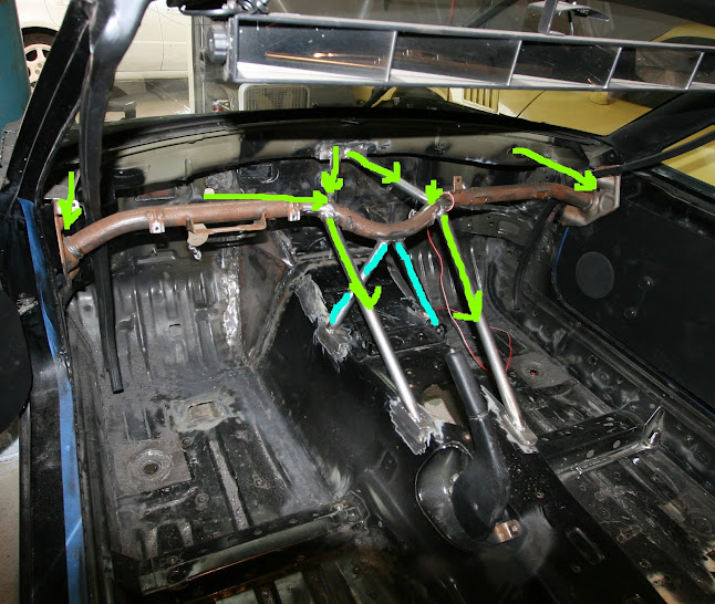
With my braces, the forces incurred during braking pass through the green lines. Tensions are generated along the teal lines. The teal areas have been braced as well.

During a right turn, the forces will pass through the green lines and tensions will be generated along the teal lines. White represents the subframe, which ties the frame rails together.

This diagram uses the same conventions. Green lines are force paths, and teal lines are tensions. This drawing represents what'll happen during braking. When turning, things will be slightly different. Note the use of triangles in some places as opposed to boxes. Those triangles prevent lateral movement, which if left unmitigated, would result in chassis twist and cowl shake.
My braces provide the forces that act on the front of the car with a good path to a relatively solid structure(trans tunnel) to reduce movement. Less movement in the chassis means that the suspension geometries stay consistent, and that the chassis won't act as a large undampened spring. The suspension will also be easier to tune when chassis movement is a less significant variable in the equation.
An excerpt from a post that I made in a thread on stitch welding. This post is also relevant to my new bracing.
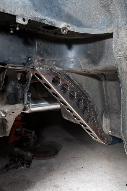
Gratuitous photos of my bracing.


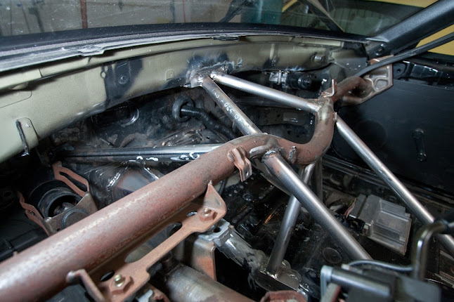

Sheet metal braces were added to help solidify the span where the upper frame rails that the suspension bolts to connect to the lower frame rails that pass beneath the car. They provide an element of triangulation.

The frame rails that pass beneath the chassis have been bolstered via the addition of bolt in frame rail braces that slip over the factory frame rails. These come as a part of the V8Roadsters swap kit, and are included in the kit because they provide a solid attachment point for the new transmission crossmember. Flyin' Miata sells frame rail braces that are suitable for those who are not performing such a swap.
The missing element now is a set of door bars. I plan to have those and a weld in roll bar fabricated by a professional at a later date.
Considerable progress has been made since my last update, and the focus of this particular post is chassis bracing. In stock form, gussets in the engine bay help transfer loads from the frame rails to the transmission tunnel, which is the most rigid structure that connects the front of the car to the back. Without those gussets, the frame rails are more free to move when forces from the road act on them via the wheels and suspension. My engine is large and sits far enough back in the bay to require the removal of those gussets--I'm okay with that because my car, in present form, should be considerably stiffer than it previously was.
An intuitive breakdown of the logic behind my bracing:
The factory engine bay has gussets in the corners that help put the forces that are applied to the frame rails though the transmission tunnel to prevent movement of the rails. The gussets are circled in red, and the green illustrates what kinds of movements the gussets reduce. Essentially, they reduce all of the movements.
Under braking, the mass of the car will transfer forward. Grip permitting, up to about 80% of the mass of a Miata could end up over the front axle during hard braking. The frame rails will push into the front subframe, and will want to move up relative to the rest of the car. The magenta arrows represent hypothetical upward movement of the frame rails. The green arrows represent the forces that that movement would generate and where they would go.
This depicts what happens during a right turn. The frame rails, liked together by the front subframe(drawn in white) will want to move in the direction of the magenta arrows. That movement will generate a force(green) though the gusset, and into the trans tunnel. The teal represents a tension that pulls on the gusset and on the trans tunnel. Note that the trans tunnel is pretty solid, so those forces will not cause it to budge much.
On the inside, the forces that are transferred though the gussets work their way into the trans tunnel. Forces also travel through the gussets in the corners of the interior. Note how the path through the trans tunnel is the most direct path for the forces to take.
So yeah, those gussets are important. What did I do with them? Well, I chopped them out to clear a big engine...man ****. Now the forces that went though the engine bay gussets don't have a sold path to the back. They'll go into bending the firewall, and through other braces such as the stamped steel brace that connect the dash bar to the trans tunnel, through the frame rails themselves, and through the rockers. That isn't the end of the world--it's also not ideal.
With my braces, the forces incurred during braking pass through the green lines. Tensions are generated along the teal lines. The teal areas have been braced as well.
During a right turn, the forces will pass through the green lines and tensions will be generated along the teal lines. White represents the subframe, which ties the frame rails together.
This diagram uses the same conventions. Green lines are force paths, and teal lines are tensions. This drawing represents what'll happen during braking. When turning, things will be slightly different. Note the use of triangles in some places as opposed to boxes. Those triangles prevent lateral movement, which if left unmitigated, would result in chassis twist and cowl shake.
My braces provide the forces that act on the front of the car with a good path to a relatively solid structure(trans tunnel) to reduce movement. Less movement in the chassis means that the suspension geometries stay consistent, and that the chassis won't act as a large undampened spring. The suspension will also be easier to tune when chassis movement is a less significant variable in the equation.
An excerpt from a post that I made in a thread on stitch welding. This post is also relevant to my new bracing.
My personal experience, for what its worth, is that my car felt fine at lower speeds(auto-x) and quite numb at higher speeds(track time). I like to have feedback when I drive, so anything that firms up the structure that separates me from the surface I'm driving on, within reason, is welcome. I'll be faster in that sense because I'll be able to react more quickly as a driver.
As for the inherent capabilities of the car, the differences may be less profound for the average enthusiast. That said, flex in the chassis could result is dynamic fluctuations in the alignment, and there's the whole big un-dampened spring thing. From that perspective, I think that the biggest advantage of stitch welding and bracing a chassis pertains to suspension tune-ability. Imagine the equation that you'd use to represent the handling characteristics of a car. Things like dynamic camber curves, spring rates, compression and rebound characteristics, caster, roll centers, toe, moments of inertia, etc....and chassis deformation. Most of those variables are consistent and predictable. Chassis deformation is not. Since you're going to have a hell of a time trying to model how the chassis will respond to infinitely many permutations of input, tuning the suspension becomes less of a science and more an act of trial and error. If you can reduce chassis flex, you have less noise in your equation, and subsequently, changes to the variables that you can control are more apt to have a tangible and predictable effect. This applies more to racing teams and enthusiasts who take the time to actually develop their cars.
As for the inherent capabilities of the car, the differences may be less profound for the average enthusiast. That said, flex in the chassis could result is dynamic fluctuations in the alignment, and there's the whole big un-dampened spring thing. From that perspective, I think that the biggest advantage of stitch welding and bracing a chassis pertains to suspension tune-ability. Imagine the equation that you'd use to represent the handling characteristics of a car. Things like dynamic camber curves, spring rates, compression and rebound characteristics, caster, roll centers, toe, moments of inertia, etc....and chassis deformation. Most of those variables are consistent and predictable. Chassis deformation is not. Since you're going to have a hell of a time trying to model how the chassis will respond to infinitely many permutations of input, tuning the suspension becomes less of a science and more an act of trial and error. If you can reduce chassis flex, you have less noise in your equation, and subsequently, changes to the variables that you can control are more apt to have a tangible and predictable effect. This applies more to racing teams and enthusiasts who take the time to actually develop their cars.
Gratuitous photos of my bracing.
Sheet metal braces were added to help solidify the span where the upper frame rails that the suspension bolts to connect to the lower frame rails that pass beneath the car. They provide an element of triangulation.
The frame rails that pass beneath the chassis have been bolstered via the addition of bolt in frame rail braces that slip over the factory frame rails. These come as a part of the V8Roadsters swap kit, and are included in the kit because they provide a solid attachment point for the new transmission crossmember. Flyin' Miata sells frame rail braces that are suitable for those who are not performing such a swap.
The missing element now is a set of door bars. I plan to have those and a weld in roll bar fabricated by a professional at a later date.
Last edited by 573; 04-05-2013 at 03:37 PM.
04-05-2013, 02:50 PM
#14
Teching In
Thread Starter
Join Date: Jul 2012
Posts: 21
Likes: 0
Received 0 Likes
on
0 Posts
December 23, 2012:
In stock form, the hood is held down by a cable actuated latch that bolts to the core support--just like any other car. That mechanism has clear advantages on a production vehicle, however my priorities differ from those of the OEM engineers. I am after security, lightness, simplicity, and serviceability.
-The snap-ring pins or cotter pins that aftermarket hood pin setups come with have been tested and proven. So have OEM hood latches. With regard to this facet, neither the OEM latch nor a set of hood pins has a significant advantage.
-The OEM mechanism is heavy and complex compared to a set of hood pins. The core support that the OEM latch mounts to also has mass.
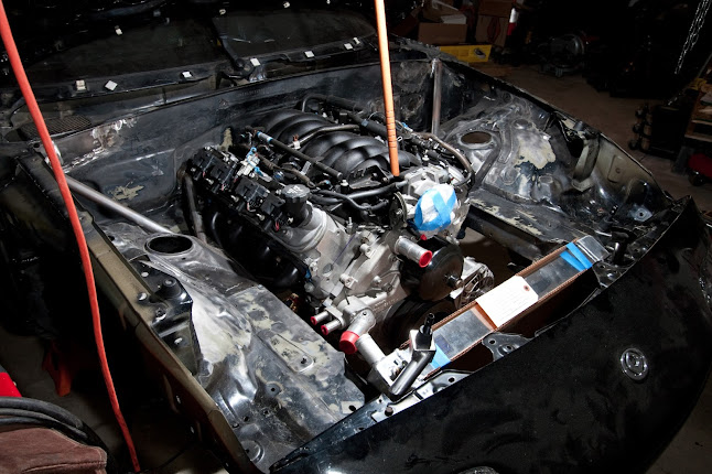
-Having the OEM core support hinders my ability to remove and reinstall the drivetrain. The core support would also make servicing the engine, while it's in the car, more difficult. To streamline the installation and removal of the drivetrain, I removed the core support and anything else that was in the way via a cutoff wheel and sawmill.
I elected to use hood pins, and I made custom mounts to support them. The mounts that I made are light weight and are bolted in as opposed to welded so that they can be removed when they are in the way. When I say in the way, I mean preventing the removal of the radiator(I may be able to revise the sway bar mounts to overcome this), and the removal of the drivetrain.
The mounts are relatively simple, so without further ado, here are some photos:
The mounts themselves consist of: 1/8" steel plate for the bases, 1/16" tubing for the arms, and formed sheet metal for the pin attachment points.

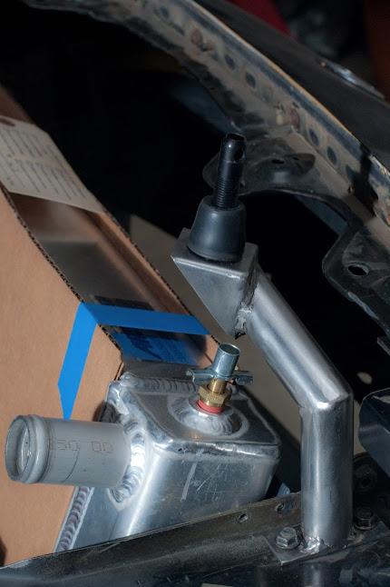

Note the gap between the hood and the bumper. I found that such a gap can be made by loosening the hood-hinge bolts and sliding the hood back. This gap is desirable, for me at least, because air will be evacuated from the engine bay via the gap. Air accelerates as it passes over that curved region of the car, resulting in lower pressure--essentially an application of Bernoulli's principle. The air in the engine bay(relatively high pressure) will want to reach equilibrium with the air over the gap(relatively low pressure), so air will be flow out through the gap, and the pressure differential across the radiator will be greater than it otherwise would be. Radiators work when air is flowing through the fins, and air is forced through the fins when a pressure differential is present. The effectiveness of this is dependent on how well the radiator is ducted to the "mouth" of the front bumper.

In stock form, the hood is held down by a cable actuated latch that bolts to the core support--just like any other car. That mechanism has clear advantages on a production vehicle, however my priorities differ from those of the OEM engineers. I am after security, lightness, simplicity, and serviceability.
-The snap-ring pins or cotter pins that aftermarket hood pin setups come with have been tested and proven. So have OEM hood latches. With regard to this facet, neither the OEM latch nor a set of hood pins has a significant advantage.
-The OEM mechanism is heavy and complex compared to a set of hood pins. The core support that the OEM latch mounts to also has mass.
-Having the OEM core support hinders my ability to remove and reinstall the drivetrain. The core support would also make servicing the engine, while it's in the car, more difficult. To streamline the installation and removal of the drivetrain, I removed the core support and anything else that was in the way via a cutoff wheel and sawmill.
I elected to use hood pins, and I made custom mounts to support them. The mounts that I made are light weight and are bolted in as opposed to welded so that they can be removed when they are in the way. When I say in the way, I mean preventing the removal of the radiator(I may be able to revise the sway bar mounts to overcome this), and the removal of the drivetrain.
The mounts are relatively simple, so without further ado, here are some photos:
The mounts themselves consist of: 1/8" steel plate for the bases, 1/16" tubing for the arms, and formed sheet metal for the pin attachment points.
Note the gap between the hood and the bumper. I found that such a gap can be made by loosening the hood-hinge bolts and sliding the hood back. This gap is desirable, for me at least, because air will be evacuated from the engine bay via the gap. Air accelerates as it passes over that curved region of the car, resulting in lower pressure--essentially an application of Bernoulli's principle. The air in the engine bay(relatively high pressure) will want to reach equilibrium with the air over the gap(relatively low pressure), so air will be flow out through the gap, and the pressure differential across the radiator will be greater than it otherwise would be. Radiators work when air is flowing through the fins, and air is forced through the fins when a pressure differential is present. The effectiveness of this is dependent on how well the radiator is ducted to the "mouth" of the front bumper.
Last edited by 573; 04-05-2013 at 03:38 PM.
04-05-2013, 02:51 PM
#15
Teching In
Thread Starter
Join Date: Jul 2012
Posts: 21
Likes: 0
Received 0 Likes
on
0 Posts
January 22, 2013:
Seeing as this is a high-power car which will see track time, the cooling infrastructure needed to be updated. The radiator which I chose is considerably larger than the factory radiator, and the stock radiator mounts were removed to make clearance for the drivetrain to conveniently go in and out of the engine bay. Some new radiator mounts needed to be made. The design which I chose for the new mounts is simple, light, and very strong. The lower mounts, that the base of the radiator slips into, are much stronger than radiator mounts need to be. The mounts are overbuilt because they will double as mounting points for a belly pan and splitter. Once I dive into aerodynamics, this car will likely end up with a splitter capable of generating considerable downforce. The splitter and belly pan also need to be strong enough to not deform under small impacts. i.e. the car bottoming out over a tall speed bump or steep driveway. My lower radiator mounts should be more than up to the task.
These are the lower mounts. 1" diameter 1/16" wall steel tubing runs down from the frame rails and is held securely in position by gussets. The pockets were made from sheet metal.

This view is looking in from the opening in the front bumper. Sheet metal was used to create a surface for the radiator to lean against and more of that same material was used to triangulate those surfaces to the frame rails, adding significant strength.

Rubber bumpers were later installed on all of the mounts to isolate the radiator from potentially harmful vibrations. The radiator is slanted for three reasons. The first two are so that the mass of the radiator can be lower and further back. The last and perhaps most important reason is to create clearance for an air intake pipe to pass from the throttle body to the front bumper without having to cut a hole in the hood or use a smushed pipe.

What you have seen up until now allows the radiator to conveniently slide in and out of the car for the sake of easy serviceability. The radiator is also held in place by what are essentially L brackets that bolt into the frame rails and apply enough pressure to the back of the radiator to hold it securely.
Seeing as this is a high-power car which will see track time, the cooling infrastructure needed to be updated. The radiator which I chose is considerably larger than the factory radiator, and the stock radiator mounts were removed to make clearance for the drivetrain to conveniently go in and out of the engine bay. Some new radiator mounts needed to be made. The design which I chose for the new mounts is simple, light, and very strong. The lower mounts, that the base of the radiator slips into, are much stronger than radiator mounts need to be. The mounts are overbuilt because they will double as mounting points for a belly pan and splitter. Once I dive into aerodynamics, this car will likely end up with a splitter capable of generating considerable downforce. The splitter and belly pan also need to be strong enough to not deform under small impacts. i.e. the car bottoming out over a tall speed bump or steep driveway. My lower radiator mounts should be more than up to the task.
These are the lower mounts. 1" diameter 1/16" wall steel tubing runs down from the frame rails and is held securely in position by gussets. The pockets were made from sheet metal.
This view is looking in from the opening in the front bumper. Sheet metal was used to create a surface for the radiator to lean against and more of that same material was used to triangulate those surfaces to the frame rails, adding significant strength.
Rubber bumpers were later installed on all of the mounts to isolate the radiator from potentially harmful vibrations. The radiator is slanted for three reasons. The first two are so that the mass of the radiator can be lower and further back. The last and perhaps most important reason is to create clearance for an air intake pipe to pass from the throttle body to the front bumper without having to cut a hole in the hood or use a smushed pipe.
What you have seen up until now allows the radiator to conveniently slide in and out of the car for the sake of easy serviceability. The radiator is also held in place by what are essentially L brackets that bolt into the frame rails and apply enough pressure to the back of the radiator to hold it securely.
Last edited by 573; 04-05-2013 at 03:38 PM.
04-05-2013, 02:53 PM
#16
Teching In
Thread Starter
Join Date: Jul 2012
Posts: 21
Likes: 0
Received 0 Likes
on
0 Posts
January 23, 2013:
There are a couple(two that I know of) aftermarket exhaust systems that companies have made for this particular swap. The available units are well constructed, however I thought that I could build an exhaust system that suited this car better, and do so for a fraction of the cost. So far, it is looking as though I have done just that. My top priorities for this exhaust system were performance and ground clearance. Performance is self explanatory. Ground clearance is also important because this car will be low to the ground and having various parts of it, namely the exhaust system, scrape the ground under certain conditions will make unfortunate noises and potentially cause damage. Stressing over the ground clearance of the exhaust system also provides more space for the addition of a full flat underbody, which has aerodynamic benefits, in the future.
I built this exhaust system from 2.5" aluminized steel pipe. I chose aluminized steel because I can weld it with equipment that I already have and it provides some corrosion resistance. The pipes were cut by a chop saw with a friction blade. Mandrel bent tubes of two different radii and straight sections of pipe were purchased. Unnecessary bends were minimized for the sake of performance. The welds were intentionally made with a cooler setting than what would normally be advised. I did this to avoid excessive penetration, which would likely result in some extra turbulence in the pipes.
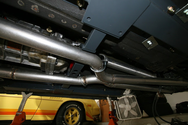
The shape of the system was chosen to maximize consistency between both banks of cylinders. Since the passenger side header lets out further forward than the drivers side header, and has a sharper bend to clear the starter motor, the x-pipe was placed closer to the passenger side to help even out the length of the two runs of pipe that lead to and from the x-pipe. The x-pipe is present to even out the pressure between the two sides of the exhaust system, allowing the system as a whole to be used more effectively. The x-pipe also results in a scavenging effect which helps exhaust gasses leave cylinders. A V8 engine has two banks of four cylinders. They fire at different times, and with each firing, a pulse, or pressure front/wave, passes through the exhaust system. Since the firing in the two banks is offset, an exhaust pulse from one bank flows downstream and reaches the x pipe when the valve, of the other cylinder bank, opens to expel combustion byproducts. (The time between those events depends on engine speed.) The effect of having a pulse from one bank enter the pipe for the other bank, via the x-pipe, is a vacuum which helps draw combustion byproducts out of the cylinder with an open exhaust valve in the adjacent cylinder bank. That increases efficiency and efficiency is the key to making power.


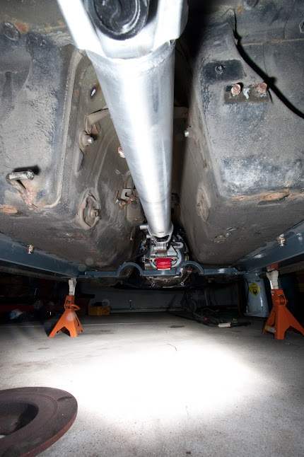
The system nicely tucks into the bottom of the car and does not have any apparent points of vulnerability.

The midsection of the system is supported by u-bolts which attach to steel braces that attach to the transmission side of the transmission mount. That way, vibrations are isolated from the chassis.

You may have noticed that this system lacks mufflers so far, or perhaps assumed that I do not value my sense of hearing. This car will not have much muffling, but it will have some so that myself and those around me can maintain some sanity. Magnaflow 6" round mufflers are being used. They are about 20" long and have a straight through design. They are not currently installed due to my running out of time, however they will simply be welded onto the end of what I have already made. I will trim the bumper cover more before I install the mufflers so that they can be mounted higher. I want to mount them as high as is reasonable to maximize the space left over for a rear diffuser, another aerodynamic downforce adder that I would like to make and install in the future.
Before trimming the bumper, the mufflers leave just enough clearance for a diffuser mounted at 10*. 7-10* is the commonly accepted sweet-spot.

This is roughly how the mufflers will look coming out of the back of the car. As previously stated, the bumper will be trimmed more and the mufflers will be mounted higher. I think they're going to look great and sound even better than they look once I'm done.

There are a couple(two that I know of) aftermarket exhaust systems that companies have made for this particular swap. The available units are well constructed, however I thought that I could build an exhaust system that suited this car better, and do so for a fraction of the cost. So far, it is looking as though I have done just that. My top priorities for this exhaust system were performance and ground clearance. Performance is self explanatory. Ground clearance is also important because this car will be low to the ground and having various parts of it, namely the exhaust system, scrape the ground under certain conditions will make unfortunate noises and potentially cause damage. Stressing over the ground clearance of the exhaust system also provides more space for the addition of a full flat underbody, which has aerodynamic benefits, in the future.
I built this exhaust system from 2.5" aluminized steel pipe. I chose aluminized steel because I can weld it with equipment that I already have and it provides some corrosion resistance. The pipes were cut by a chop saw with a friction blade. Mandrel bent tubes of two different radii and straight sections of pipe were purchased. Unnecessary bends were minimized for the sake of performance. The welds were intentionally made with a cooler setting than what would normally be advised. I did this to avoid excessive penetration, which would likely result in some extra turbulence in the pipes.
The shape of the system was chosen to maximize consistency between both banks of cylinders. Since the passenger side header lets out further forward than the drivers side header, and has a sharper bend to clear the starter motor, the x-pipe was placed closer to the passenger side to help even out the length of the two runs of pipe that lead to and from the x-pipe. The x-pipe is present to even out the pressure between the two sides of the exhaust system, allowing the system as a whole to be used more effectively. The x-pipe also results in a scavenging effect which helps exhaust gasses leave cylinders. A V8 engine has two banks of four cylinders. They fire at different times, and with each firing, a pulse, or pressure front/wave, passes through the exhaust system. Since the firing in the two banks is offset, an exhaust pulse from one bank flows downstream and reaches the x pipe when the valve, of the other cylinder bank, opens to expel combustion byproducts. (The time between those events depends on engine speed.) The effect of having a pulse from one bank enter the pipe for the other bank, via the x-pipe, is a vacuum which helps draw combustion byproducts out of the cylinder with an open exhaust valve in the adjacent cylinder bank. That increases efficiency and efficiency is the key to making power.
The system nicely tucks into the bottom of the car and does not have any apparent points of vulnerability.
The midsection of the system is supported by u-bolts which attach to steel braces that attach to the transmission side of the transmission mount. That way, vibrations are isolated from the chassis.
You may have noticed that this system lacks mufflers so far, or perhaps assumed that I do not value my sense of hearing. This car will not have much muffling, but it will have some so that myself and those around me can maintain some sanity. Magnaflow 6" round mufflers are being used. They are about 20" long and have a straight through design. They are not currently installed due to my running out of time, however they will simply be welded onto the end of what I have already made. I will trim the bumper cover more before I install the mufflers so that they can be mounted higher. I want to mount them as high as is reasonable to maximize the space left over for a rear diffuser, another aerodynamic downforce adder that I would like to make and install in the future.
Before trimming the bumper, the mufflers leave just enough clearance for a diffuser mounted at 10*. 7-10* is the commonly accepted sweet-spot.
This is roughly how the mufflers will look coming out of the back of the car. As previously stated, the bumper will be trimmed more and the mufflers will be mounted higher. I think they're going to look great and sound even better than they look once I'm done.
Last edited by 573; 04-05-2013 at 03:39 PM.
04-05-2013, 02:55 PM
#17
Teching In
Thread Starter
Join Date: Jul 2012
Posts: 21
Likes: 0
Received 0 Likes
on
0 Posts
January 24, 2013
I have done a number of things to this car to improve the static front/rear weight bias, and amongst them was moving the drivers seat as far back as it can possibly go. I made a new seat bracket early on that moved the seat back and optimized the positioning of my custom pedal assembly to work with the new seat position. The pedals, however, are not the only control that I need to be able to reach. The steering wheel needed to be about 6.5" further back. A simple means of handling this is to make a steering wheel extender. To do that, I merged the base of the OEM wheel hub, which bolts to the steering column, to the front part of my Sparco steering wheel hub, which the wheel screws into, with a spacer in between. The base of the OEM hub and the front part of the Sparco hub are both made of mild steel, and I happened to have some scraps of 2.5" exhaust tubing laying around. I cut the tubing to the correct length and welded the pieces together.
After optimizing the distance between the wheel and driver, I had to optimize the angle of the steering column because the extender alone placed the wheel up far too high--the top of the wheel obstructed my view out the windshield. This meant lengthening the mounts that hold the steering column to the dash bar, lowering the steering column itself. I ground off the old mount and welded my longer mounts in place.
Firstly, the OEM steering wheel hub resembles a slice of bread.

This photo illustrates the excessive angle that was present, placing the wheel too high, before I updated the steering column mounts to lower it.

After I adjusted the angle.


Optimal position is generally regarded as when you can rest the bottom of your wrist on top of the wheel without leaning forward. I'd say this is dead-on.

I have done a number of things to this car to improve the static front/rear weight bias, and amongst them was moving the drivers seat as far back as it can possibly go. I made a new seat bracket early on that moved the seat back and optimized the positioning of my custom pedal assembly to work with the new seat position. The pedals, however, are not the only control that I need to be able to reach. The steering wheel needed to be about 6.5" further back. A simple means of handling this is to make a steering wheel extender. To do that, I merged the base of the OEM wheel hub, which bolts to the steering column, to the front part of my Sparco steering wheel hub, which the wheel screws into, with a spacer in between. The base of the OEM hub and the front part of the Sparco hub are both made of mild steel, and I happened to have some scraps of 2.5" exhaust tubing laying around. I cut the tubing to the correct length and welded the pieces together.
After optimizing the distance between the wheel and driver, I had to optimize the angle of the steering column because the extender alone placed the wheel up far too high--the top of the wheel obstructed my view out the windshield. This meant lengthening the mounts that hold the steering column to the dash bar, lowering the steering column itself. I ground off the old mount and welded my longer mounts in place.
Firstly, the OEM steering wheel hub resembles a slice of bread.
This photo illustrates the excessive angle that was present, placing the wheel too high, before I updated the steering column mounts to lower it.
After I adjusted the angle.
Optimal position is generally regarded as when you can rest the bottom of your wrist on top of the wheel without leaning forward. I'd say this is dead-on.
Last edited by 573; 04-05-2013 at 03:40 PM.
04-05-2013, 02:58 PM
#18
Teching In
Thread Starter
Join Date: Jul 2012
Posts: 21
Likes: 0
Received 0 Likes
on
0 Posts
January 24, 2013:
We all know the importance of reliable brakes. When you push the stop pedal, the car better slow down. No exceptions, ever. Ensuring that that is the case involves more than having physically strong components. The components have to be appropriately sized for the application, must be able to dissipate a sufficient amount of heat, and the components also have to be appropriate for the temperatures that they will reach(i.e. a track car requires pads that can handle hotter temperateness than a street car). How much heat do brakes generate under hard stopping? Well, brakes work by using friction to resist movement. Friction is what warms your hands when you rub them together. Now imagine that your hands were rougher, you pushed them together with 4,000 pounds of force, and you rubbed them together at 112 feet per second. The cited force is an approximation of what will happen when I start to brake at the end of a 150mph straight--112 f/s is the speed of the outsides of the rotors relative to the calipers at 150mph. This is true for each corner in the front, and the numbers for the rears are about 20% of the numbers cited for the fronts. Your hands will not hold up to that and a lot of brake systems will not hold up to that either. Lots of heat is created, and the amount of energy that the brakes must absorb is exponentially proportional to the velocity of the vehicle. The heat is dealt with by using large vented rotors, using pads that retain their coefficient of friction under extreme conditions, and in some cases, by ducting air to the rotors for additional cooling. I'm doing the first two, and may have to do the last as well--time will tell.
Under heavy braking, a larger portion of the mass of the vehicle is over the front wheels. On a Miata with significant grip, the dynamic front weight bias could be as high as ~80% under heavy braking. This means that if you want to utilize all available grip to slow the car down, the brakes should have the same front bias as the dynamic front weight bias. That being said, it is common to give brakes additional front bias for the sake of safety. The car would have a tendency to spin out if the rear wheels locked up before the fronts, so brake systems are engineered to have the fronts lock up first. My brakes are no exception to this, however I am using a balance bar for fine control over front/rear bias. The balance bar will allow me to make adjustments to the bias, while strapped into my seat, to optimize the settings for the conditions that I am driving under. Other ways to adjust the bias are to adjust the caliper piston sizes, the number of pistons in the calipers, the diameter of the rotors, the diameter of the master cylinders, and the friction coefficient of the pads. These same things can be adjusted, as well as the pedal ratio(think mechanical leverage), to alter the amount of force the driver must exert to achieve the same outcome at the wheels. One thing to be mindful of is that nothing comes for free--if you have a pedal that requires little effort, that pedal will also have to be pushed further.
For the rotors and calipers, I chose to go with a proven setup. I got the Trackspeed Engineering front big brake kit and M-Tuned caliper spacers for the rear. The front setup includes 11.75" Wilwood rotors and 4-piston Wilwood calipers. The pistons are 1.38" in diameter. The kit also includes brackets and stainless steel lines that make these brakes plug and play. Trackspeed Engineering's attention to detail manifests itself in things like safety wire to keep the bolts that connect the rotors to the top-hats from backing out. They also provide a good set of installation instructions. The stock rear calipers will be retained and spaced out further via brackets to allow clearance for 10.9" sport rotors, which came on the Mazdaspeed Miata. Wilwood master cylinders were used for the brakes and clutch. I am not going to share the specifics there because my master cylinder choices, as well as the pedal ratios, have yet to be tested and proven. That said, my math indicates that there should be no issues. The pedals themselves are from a 2004 Pontiac GTO. They came with my drivetrain and have been modified to suit my application. The modifications included cutting and welding to alter the overall lengths and pivot points. The gas pedal was the simplest part, and minimal modification was necessary. I welded mounts into the car for the gas pedal to bolt onto, and added a point to the pedal assembly to provide the throttle cable with a place to attach in the new configuration.
In addition to greater capacity, these brakes weigh less than the stock components, and consumable items(pads and rotors) will last longer and are cheaper to replace.

Early stages of the pedal box. The balance bar is clearly visible here. The pivot point is adjustable so the forces applied to the front and rear master cylinders can be varied.

This is the finished pedal box.


You can see roughly how the pedal assembly is mounted and also the addition of a switch, which will operate the brake lights.


Can't forget the gas pedal.

All three can be operated as needed. The gas pedal was placed with heel-toe shifting in mind.

The plumbing still has to be done. Steel hard lines will be run through the interior to the front and back, and tee off at the ends to provide pressure to the calipers on both sides. The stock rear subframe comes with a tee fitting bolted to the passenger side. I relocated that to the drivers side to better accomodate my intended line routing.
We all know the importance of reliable brakes. When you push the stop pedal, the car better slow down. No exceptions, ever. Ensuring that that is the case involves more than having physically strong components. The components have to be appropriately sized for the application, must be able to dissipate a sufficient amount of heat, and the components also have to be appropriate for the temperatures that they will reach(i.e. a track car requires pads that can handle hotter temperateness than a street car). How much heat do brakes generate under hard stopping? Well, brakes work by using friction to resist movement. Friction is what warms your hands when you rub them together. Now imagine that your hands were rougher, you pushed them together with 4,000 pounds of force, and you rubbed them together at 112 feet per second. The cited force is an approximation of what will happen when I start to brake at the end of a 150mph straight--112 f/s is the speed of the outsides of the rotors relative to the calipers at 150mph. This is true for each corner in the front, and the numbers for the rears are about 20% of the numbers cited for the fronts. Your hands will not hold up to that and a lot of brake systems will not hold up to that either. Lots of heat is created, and the amount of energy that the brakes must absorb is exponentially proportional to the velocity of the vehicle. The heat is dealt with by using large vented rotors, using pads that retain their coefficient of friction under extreme conditions, and in some cases, by ducting air to the rotors for additional cooling. I'm doing the first two, and may have to do the last as well--time will tell.
Under heavy braking, a larger portion of the mass of the vehicle is over the front wheels. On a Miata with significant grip, the dynamic front weight bias could be as high as ~80% under heavy braking. This means that if you want to utilize all available grip to slow the car down, the brakes should have the same front bias as the dynamic front weight bias. That being said, it is common to give brakes additional front bias for the sake of safety. The car would have a tendency to spin out if the rear wheels locked up before the fronts, so brake systems are engineered to have the fronts lock up first. My brakes are no exception to this, however I am using a balance bar for fine control over front/rear bias. The balance bar will allow me to make adjustments to the bias, while strapped into my seat, to optimize the settings for the conditions that I am driving under. Other ways to adjust the bias are to adjust the caliper piston sizes, the number of pistons in the calipers, the diameter of the rotors, the diameter of the master cylinders, and the friction coefficient of the pads. These same things can be adjusted, as well as the pedal ratio(think mechanical leverage), to alter the amount of force the driver must exert to achieve the same outcome at the wheels. One thing to be mindful of is that nothing comes for free--if you have a pedal that requires little effort, that pedal will also have to be pushed further.
For the rotors and calipers, I chose to go with a proven setup. I got the Trackspeed Engineering front big brake kit and M-Tuned caliper spacers for the rear. The front setup includes 11.75" Wilwood rotors and 4-piston Wilwood calipers. The pistons are 1.38" in diameter. The kit also includes brackets and stainless steel lines that make these brakes plug and play. Trackspeed Engineering's attention to detail manifests itself in things like safety wire to keep the bolts that connect the rotors to the top-hats from backing out. They also provide a good set of installation instructions. The stock rear calipers will be retained and spaced out further via brackets to allow clearance for 10.9" sport rotors, which came on the Mazdaspeed Miata. Wilwood master cylinders were used for the brakes and clutch. I am not going to share the specifics there because my master cylinder choices, as well as the pedal ratios, have yet to be tested and proven. That said, my math indicates that there should be no issues. The pedals themselves are from a 2004 Pontiac GTO. They came with my drivetrain and have been modified to suit my application. The modifications included cutting and welding to alter the overall lengths and pivot points. The gas pedal was the simplest part, and minimal modification was necessary. I welded mounts into the car for the gas pedal to bolt onto, and added a point to the pedal assembly to provide the throttle cable with a place to attach in the new configuration.
In addition to greater capacity, these brakes weigh less than the stock components, and consumable items(pads and rotors) will last longer and are cheaper to replace.
Early stages of the pedal box. The balance bar is clearly visible here. The pivot point is adjustable so the forces applied to the front and rear master cylinders can be varied.
This is the finished pedal box.
You can see roughly how the pedal assembly is mounted and also the addition of a switch, which will operate the brake lights.
Can't forget the gas pedal.
All three can be operated as needed. The gas pedal was placed with heel-toe shifting in mind.
The plumbing still has to be done. Steel hard lines will be run through the interior to the front and back, and tee off at the ends to provide pressure to the calipers on both sides. The stock rear subframe comes with a tee fitting bolted to the passenger side. I relocated that to the drivers side to better accomodate my intended line routing.
04-05-2013, 03:02 PM
#19
Teching In
Thread Starter
Join Date: Jul 2012
Posts: 21
Likes: 0
Received 0 Likes
on
0 Posts
January 31, 2013:
This is a post for some of the little things that currently sit at varying levels of completeness. Things that are not ready for their own posts, but still deserving of attention.
Firstly, some overall photos of the engine bay. You can see the custom coolant expansion tank that one of my racing buddies fabricated.
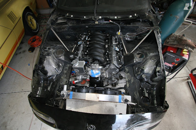


These holes allow cool air from the naturally pressurized cowl to flow into the passenger compartment.
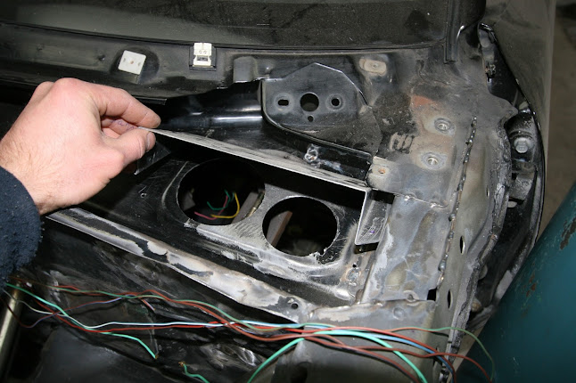
Aluminium cover to prevent water from entering the vent holes.

Another aluminum cover to keep water out of the factory HVAC inlet.

The engine wire harness has been thinned. All unnecessary wires were removed. The wiring will get a dedicated post once it's done.
This is the harness after I stripped the loom and electrical tape, and before I started removing wires.

The junk that I removed.

The harness, post thinning.

The harness reinstalled on the engine with nice wire loom.

The PCM was mounted in the passenger footwell via rubber vibration isolating mounts.
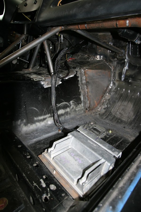
An aluminium shield protects the wires and connectors from unruly feet.

The factory crash beam was motivated to leave via sawzall. I did that to facilitate the removal and installation of the drietrain. I made a bolt in crash beam to put in its place. My structure seems to be of greater strength and since it bolts in, servicing the engine will be a breeze.

One of the best things about my new crash beam is that the OEM bumper beam fits snugly over it.

I needed more clearance between the front of the engine and the swaybar so I replaced the GTO harmonic balancer with the shallower CTS-V harmonic balancer. I now have ample clearance.

All of the old control arm bushings were removed via the Harbor Freight ball joint service tool. The ball joint tool made the job significantly easier. Stiffer urethane bushings will be going in their place once the arms are cleaned up and repainted.

The Canton Racing oil cooler was mounted. More on this later when I write a post on the oil system.

The Accusump oil pressure accumulator was mounted beneath the trunk pan.

The stout Getrag differential has been mounted to the Miata subframe.


It's a big fellow.

A Walbro 255 fuel pump is now installed in the tank.

And there you have it--a shotgun progress update.
This is a post for some of the little things that currently sit at varying levels of completeness. Things that are not ready for their own posts, but still deserving of attention.
Firstly, some overall photos of the engine bay. You can see the custom coolant expansion tank that one of my racing buddies fabricated.
These holes allow cool air from the naturally pressurized cowl to flow into the passenger compartment.
Aluminium cover to prevent water from entering the vent holes.
Another aluminum cover to keep water out of the factory HVAC inlet.
The engine wire harness has been thinned. All unnecessary wires were removed. The wiring will get a dedicated post once it's done.
This is the harness after I stripped the loom and electrical tape, and before I started removing wires.
The junk that I removed.
The harness, post thinning.
The harness reinstalled on the engine with nice wire loom.
The PCM was mounted in the passenger footwell via rubber vibration isolating mounts.
An aluminium shield protects the wires and connectors from unruly feet.
The factory crash beam was motivated to leave via sawzall. I did that to facilitate the removal and installation of the drietrain. I made a bolt in crash beam to put in its place. My structure seems to be of greater strength and since it bolts in, servicing the engine will be a breeze.
One of the best things about my new crash beam is that the OEM bumper beam fits snugly over it.
I needed more clearance between the front of the engine and the swaybar so I replaced the GTO harmonic balancer with the shallower CTS-V harmonic balancer. I now have ample clearance.
All of the old control arm bushings were removed via the Harbor Freight ball joint service tool. The ball joint tool made the job significantly easier. Stiffer urethane bushings will be going in their place once the arms are cleaned up and repainted.
The Canton Racing oil cooler was mounted. More on this later when I write a post on the oil system.
The Accusump oil pressure accumulator was mounted beneath the trunk pan.
The stout Getrag differential has been mounted to the Miata subframe.
It's a big fellow.
A Walbro 255 fuel pump is now installed in the tank.
And there you have it--a shotgun progress update.
Last edited by 573; 04-05-2013 at 03:43 PM.
04-05-2013, 03:03 PM
#20
Teching In
Thread Starter
Join Date: Jul 2012
Posts: 21
Likes: 0
Received 0 Likes
on
0 Posts
March 20, 2013:
Yeah, that's right, progress. I had some opportunities to work on this car over spring break....so I did. The outcome was a fair amount of electrical work and the first hint of life that the car has shown in many months.
For those not familiar with the early stages of this project, I removed nearly all of the factory wiring during disassembly. The process was not delicate--I marked what I intended to reuse and tore out the rest with cable cutters. I was left with a few wires in the car and a full trash bag of wires sitting on the ground, adjacent. Wanton destruction? No, not at all. The great wire massacre of 2012 paved the way for me to make a much lighter and simpler wiring harness. Who doesn't love lightness and simplicity? This all-business harness has custom routing, was laid out with an emphasis on serviceability(fuses and connections are easily accessible), is clear of things that may wish it harm(tires and excessive heat), and will have some antitheft measures built in.
Note that this has not been finalized. This is a progress photo. A few more wires need to be added before I can finish it off with loom and a vast quantity of zip ties.
The fuse/relay panel is mounted to the dash bar, beneath the airbag cutout in the dash. This keeps everything protected and out of the way while still easily accessible from inside the car. A stuffed turtle will be set on top of this panel as seen on the site banner.
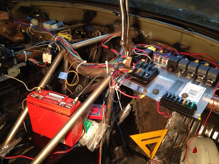
At this point, all of the lighting works. The low beams, high beams, turn signals, tail lights, and brake lights are fully functional. Integration with the already prepared engine harness comes next.
Stay tuned for a more thorough post once the wiring is finalized.
Yeah, that's right, progress. I had some opportunities to work on this car over spring break....so I did. The outcome was a fair amount of electrical work and the first hint of life that the car has shown in many months.
For those not familiar with the early stages of this project, I removed nearly all of the factory wiring during disassembly. The process was not delicate--I marked what I intended to reuse and tore out the rest with cable cutters. I was left with a few wires in the car and a full trash bag of wires sitting on the ground, adjacent. Wanton destruction? No, not at all. The great wire massacre of 2012 paved the way for me to make a much lighter and simpler wiring harness. Who doesn't love lightness and simplicity? This all-business harness has custom routing, was laid out with an emphasis on serviceability(fuses and connections are easily accessible), is clear of things that may wish it harm(tires and excessive heat), and will have some antitheft measures built in.
Note that this has not been finalized. This is a progress photo. A few more wires need to be added before I can finish it off with loom and a vast quantity of zip ties.
The fuse/relay panel is mounted to the dash bar, beneath the airbag cutout in the dash. This keeps everything protected and out of the way while still easily accessible from inside the car. A stuffed turtle will be set on top of this panel as seen on the site banner.
At this point, all of the lighting works. The low beams, high beams, turn signals, tail lights, and brake lights are fully functional. Integration with the already prepared engine harness comes next.
Stay tuned for a more thorough post once the wiring is finalized.

