
06 Lexus IS250 LS1 Build
 06-15-2013, 12:55 AM
#1
Staging Lane
Thread Starter
iTrader: (4)

Join Date: Oct 2011
Location: Jupiter, FL
Posts: 98
Likes: 0
Received 0 Likes
on
0 Posts
I have been working on this swap now for most of 2013 and posting progress on the clublexus forum. Before I started the swap I spent all of last year rebuilding the LS1 and could not have done it without the LS1tech forum, it's an awesome community. So I'll bring you guys up to speed and then post to both forums. I was also planning on posting pics from the engine build that never got around to posting before. Hope you all enjoy and thanks for the help.
 06-15-2013, 12:57 AM
#2
Staging Lane
Thread Starter
iTrader: (4)
Join Date: Oct 2011
Location: Jupiter, FL
Posts: 98
Likes: 0
Received 0 Likes
on
0 Posts
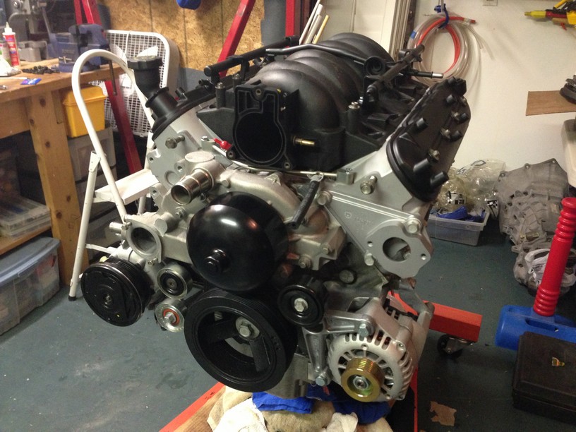
I've wanted to do an engine swap for several years now and something always seemed to get in the way. Well now the time has come. About a year ago I was given an LS1 longblock from a 2001 Camaro SS. The engine hydro-locked and bent a connecting rod. What started out as a budget rebuild with a new rod, gaskets, and piston rings turned into a year long several thousand dollar rebuild. Don't get too excited when I say a year long build, my second daughter was born the same week I was given the engine so I was a little preoccupied with family and work life.
When I first got the engine I had every intention of swapping it into an IS300. I saw what ATSMATT from clublexus.com did and I was blown away. It was an awesome swap and about the cleanest install possible. However, over the year that I was rebuilding the engine, the second gen IS's were dropping in price and the more I looked the more I liked the second gen design over the first (even though I think the IS300 is an awesome car). I finally found a pretty good deal on a 2006 Glacier Frost Mica IS250 and I bought it. It ran fine so it was a shame to tear it apart but I had to stick with the plan.
Mentally preparing for the swap
Engine covers removed
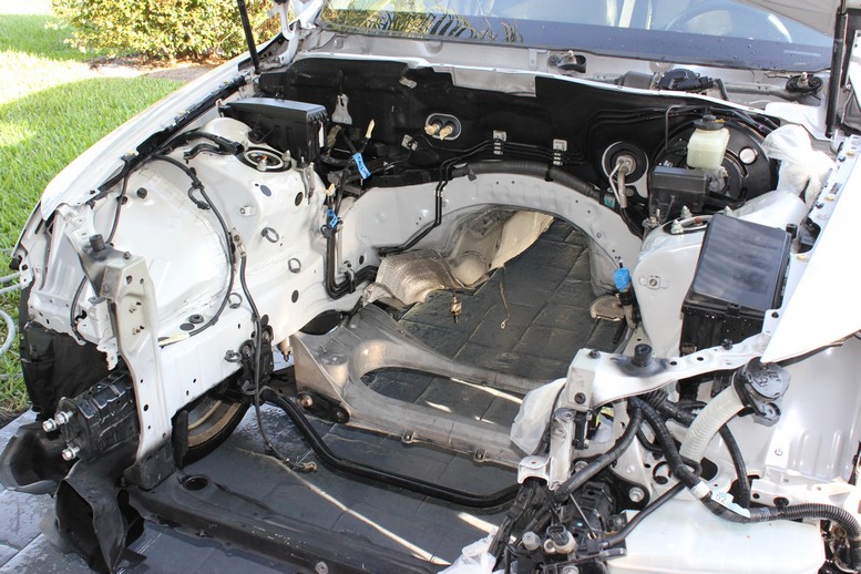
Bumper and headlights removed
That was enough damage for night 1.
When I first got the engine I had every intention of swapping it into an IS300. I saw what ATSMATT from clublexus.com did and I was blown away. It was an awesome swap and about the cleanest install possible. However, over the year that I was rebuilding the engine, the second gen IS's were dropping in price and the more I looked the more I liked the second gen design over the first (even though I think the IS300 is an awesome car). I finally found a pretty good deal on a 2006 Glacier Frost Mica IS250 and I bought it. It ran fine so it was a shame to tear it apart but I had to stick with the plan.
Mentally preparing for the swap
Engine covers removed
Bumper and headlights removed
That was enough damage for night 1.
06-15-2013, 12:58 AM
#3
Staging Lane
Thread Starter
iTrader: (4)
Join Date: Oct 2011
Location: Jupiter, FL
Posts: 98
Likes: 0
Received 0 Likes
on
0 Posts
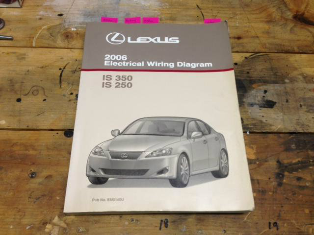
Day 2 focused on electrical diagnostics. I am trying to keep as many features working as possible which I don't think will be easy. I purchased the electrical wiring diagram manual for the car which has already proven to be a huge help.
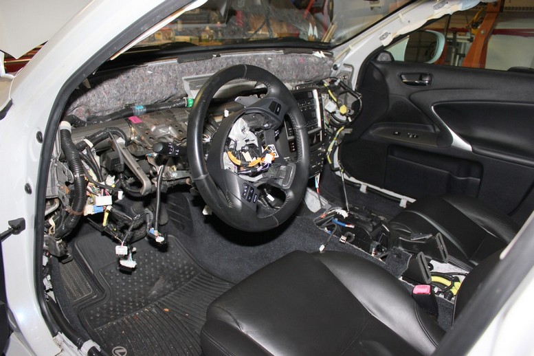
I removed the entire dash and center console. I knew I would need access everywhere so I figured why not knock it out in 1 night instead of removing it piece by piece throughout the project.
I was able to diagnose most of the electrical circuits on my list. My only failure to date is that I have not been successful at activating the electric power steering (eps) without the engine running. The eps ecu only has 5 inputs; power, ground, ignition, and 2 inputs from the can bus. The can bus inputs read roughly 2.5V each when the engine is running but since it's most likely a digital signal I'm not quite sure how I would replicate the signal.
At this point I'm thinking about replacing eps with a hydraulic setup for several reasons. First I already have the power steering pump on the LS1, second I have heard about some problems with the IS eps so now would be the best time to mitigate the risk, and lastly I can probably sell my working setup for significantly more than the cost of a new hydraulic rack. I'll resolve this a little later but if there are any eps experts out there please drop me a line.
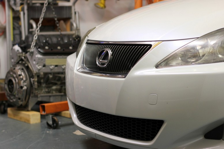
To finish off this somewhat boring entry I'll leave you with a little eye candy
I removed the entire dash and center console. I knew I would need access everywhere so I figured why not knock it out in 1 night instead of removing it piece by piece throughout the project.
I was able to diagnose most of the electrical circuits on my list. My only failure to date is that I have not been successful at activating the electric power steering (eps) without the engine running. The eps ecu only has 5 inputs; power, ground, ignition, and 2 inputs from the can bus. The can bus inputs read roughly 2.5V each when the engine is running but since it's most likely a digital signal I'm not quite sure how I would replicate the signal.
At this point I'm thinking about replacing eps with a hydraulic setup for several reasons. First I already have the power steering pump on the LS1, second I have heard about some problems with the IS eps so now would be the best time to mitigate the risk, and lastly I can probably sell my working setup for significantly more than the cost of a new hydraulic rack. I'll resolve this a little later but if there are any eps experts out there please drop me a line.
To finish off this somewhat boring entry I'll leave you with a little eye candy
06-15-2013, 12:59 AM
#4
Staging Lane
Thread Starter
iTrader: (4)
Join Date: Oct 2011
Location: Jupiter, FL
Posts: 98
Likes: 0
Received 0 Likes
on
0 Posts
I sort of combined day 2 and 3 in the last post. The initial electrical testing took pretty long and I'm sure I have more of that to come.
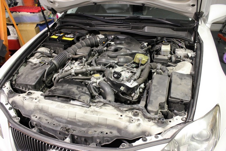
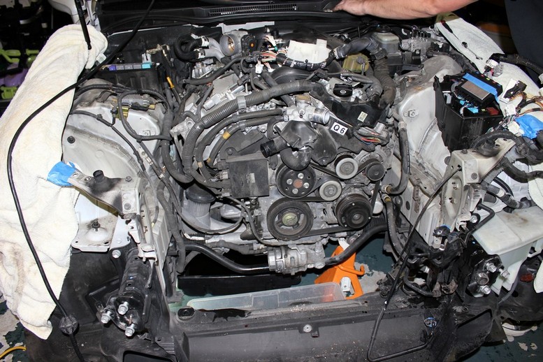
Day 4 and 5 were awesome. My buddy Jesse came over and we tore into the engine. On day 4 we drained the fluids, removed the front cross members, removed the radiator, and detached pretty much every connection to the engine. We had call it quits for the night because the manifold bolts were seized up and I was out of PB Blaster and butane for my torch.
Here's how the engine looked after day 4
DAY 5 - ENGINE REMOVAL
After breaking the exhaust manifolds from the rest of the exhaust and detaching the fuel system, we decided to remove the intake manifold in order to buy us some more clearance when we pulled the engine.
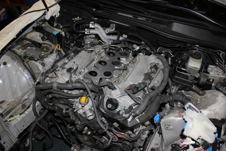
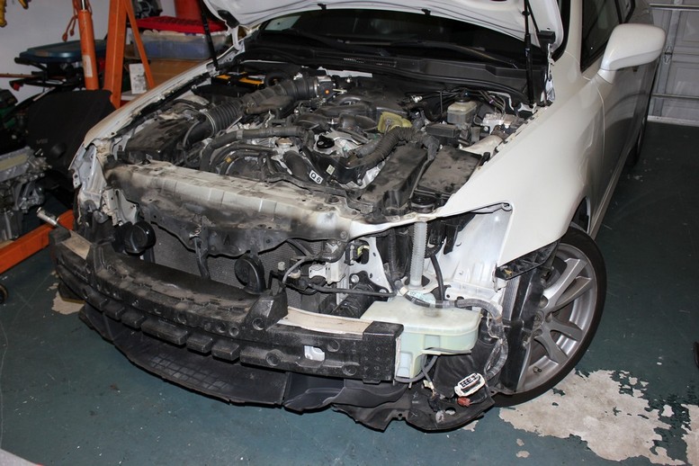
We then supported the transmission, removed the transmission cross member, removed the lower engine mount nuts and after a quick spot check we started lifting out the engine. With a little shaking and bumping the engine lifted out pretty easily.
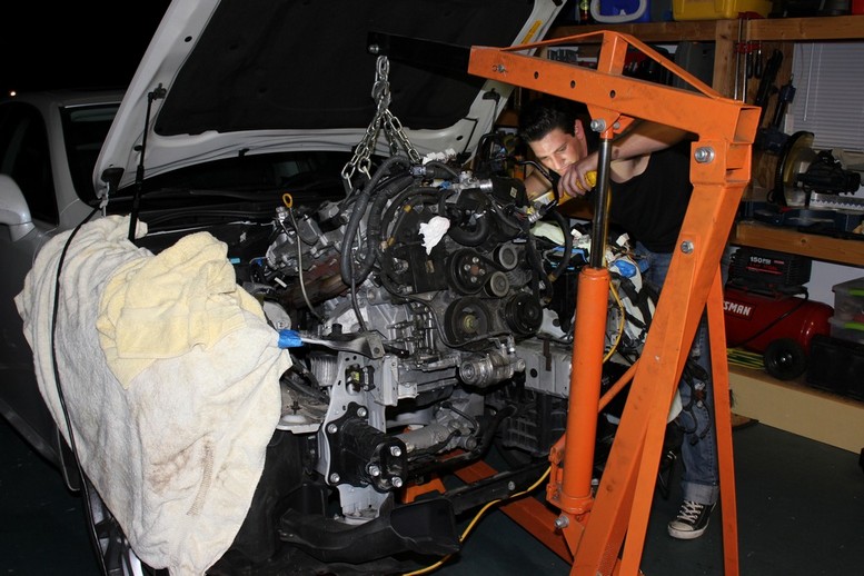
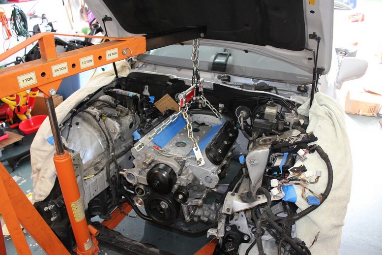
Here's the last pic of the night, It's a big engine bay, almost looks like I can fit two LS1s in there.

Day 4 and 5 were awesome. My buddy Jesse came over and we tore into the engine. On day 4 we drained the fluids, removed the front cross members, removed the radiator, and detached pretty much every connection to the engine. We had call it quits for the night because the manifold bolts were seized up and I was out of PB Blaster and butane for my torch.
Here's how the engine looked after day 4
DAY 5 - ENGINE REMOVAL
After breaking the exhaust manifolds from the rest of the exhaust and detaching the fuel system, we decided to remove the intake manifold in order to buy us some more clearance when we pulled the engine.
We then supported the transmission, removed the transmission cross member, removed the lower engine mount nuts and after a quick spot check we started lifting out the engine. With a little shaking and bumping the engine lifted out pretty easily.
Here's the last pic of the night, It's a big engine bay, almost looks like I can fit two LS1s in there.
06-15-2013, 01:00 AM
#5
Staging Lane
Thread Starter
iTrader: (4)
Join Date: Oct 2011
Location: Jupiter, FL
Posts: 98
Likes: 0
Received 0 Likes
on
0 Posts
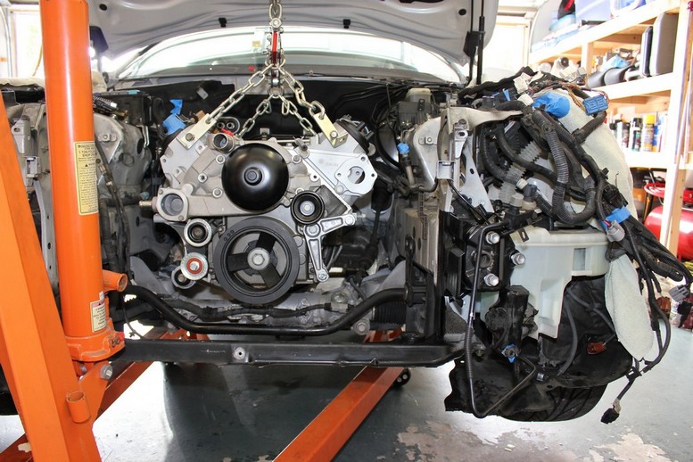
I was planning on taking a bunch of measurements once the engine was out but I couldn't wait for the first test fit. The LS1 fit in well but there is definitely a sweet spot between the bell housing hitting the top of the transmission tunnel and the bottom of the engine clearing the lower cross member enough to fit an oil pan. The engine sits pretty low in the bay which fine by me since hood clearance shouldn't be a problem and so my cg stays nice and low.
Side to side there is a ton of room. The LS1 is probably 5 inches narrower than the 4GR-FSE so I can pretty much reach my whole are down the side of the engine.
I think I might luck out with the transmission brace. The existing transmission brace was about 6 inches forward of the new support location. I saw a few black caps behind the existing brace and when I pulled one of them off there was another set of tapped holes in the chassis almost exactly where I need them. Hopefully I'll be able to get away with some drilling and shimming of the existing transmission brace.
Next on the list is measuring for engine mounts and once I get the mount material on order I'll be installing the clutch pedal. Hopefully that can all take place this weekend.
06-15-2013, 01:02 AM
#6
Staging Lane
Thread Starter
iTrader: (4)
Join Date: Oct 2011
Location: Jupiter, FL
Posts: 98
Likes: 0
Received 0 Likes
on
0 Posts
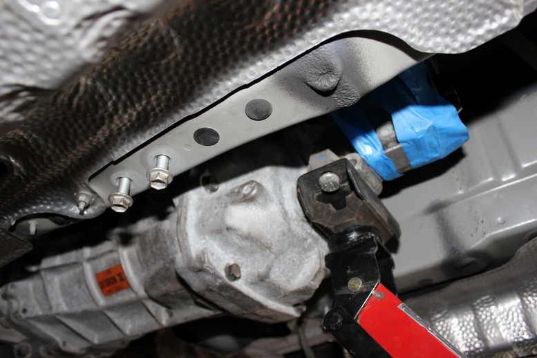
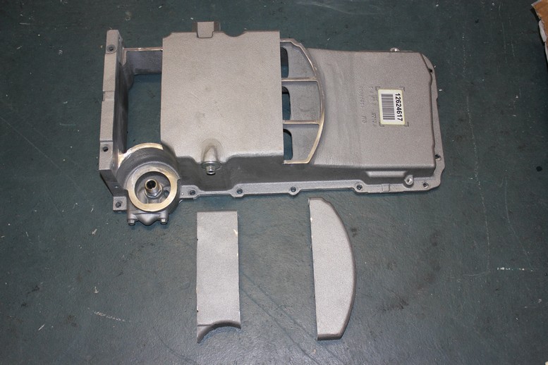
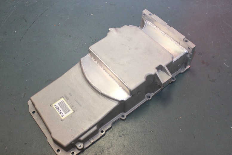
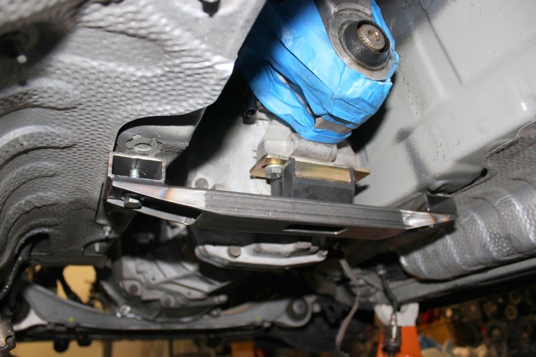
Sorry I haven't posted in a while but I finally found some time to spend on the car. I got an LS2 rear sump pan that I had to cut it to fit between the two lower front cross members. I guess it's a mid sump pan now. I installed it back in the car for a test fit but I'll eventually patch the cutouts with some aluminum plate.
Here's the cut up pan. I'll need a oil filter relocation kit since the filter fall right over the back cross member.
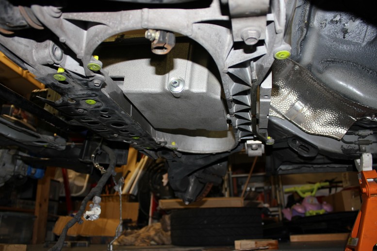
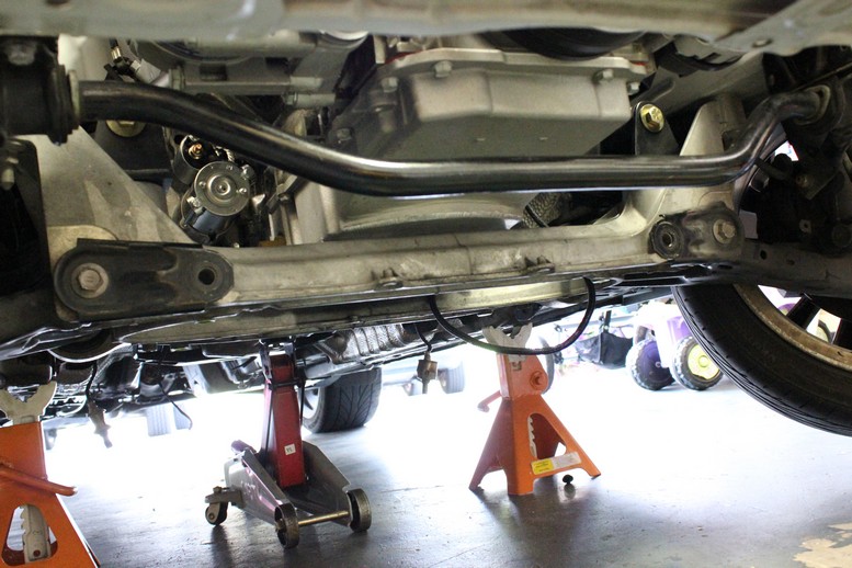
And here's a view from under the car
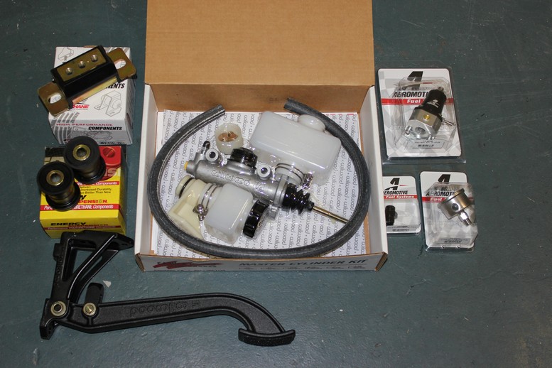
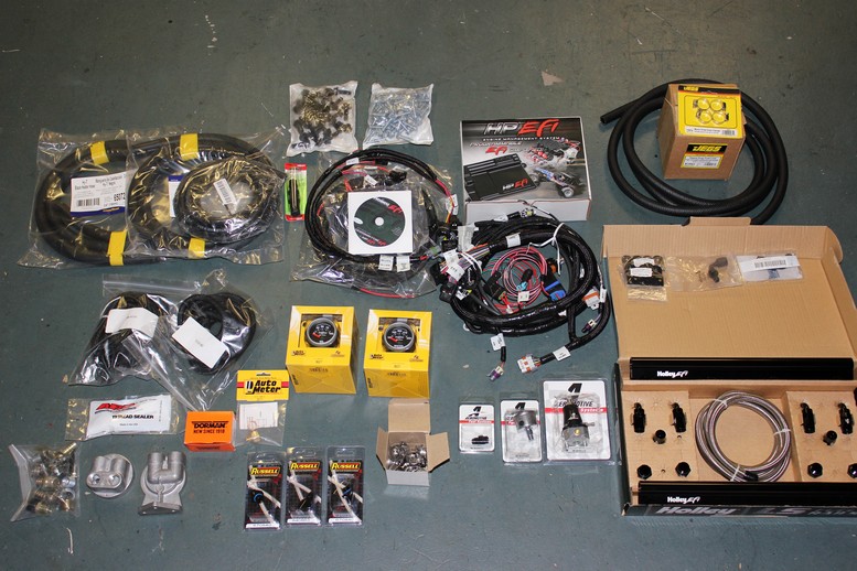
I also got some other parts since my last post
I cut the hole in the firewall for the master cylinder but I still need to modify the clutch pedal before I install the cylinder and pedal.

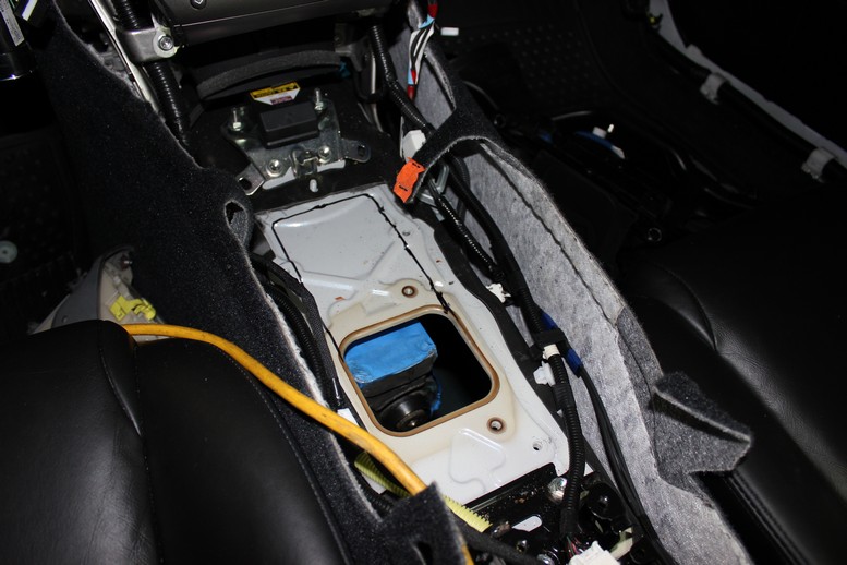
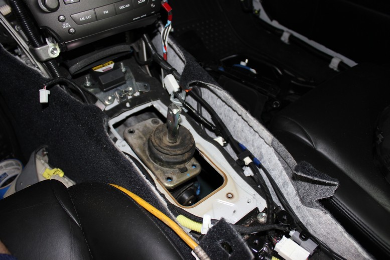
Last thing I did tonight was cut the center console for the shifter. Here's the first pick if how the shifter location lines up with the stock location
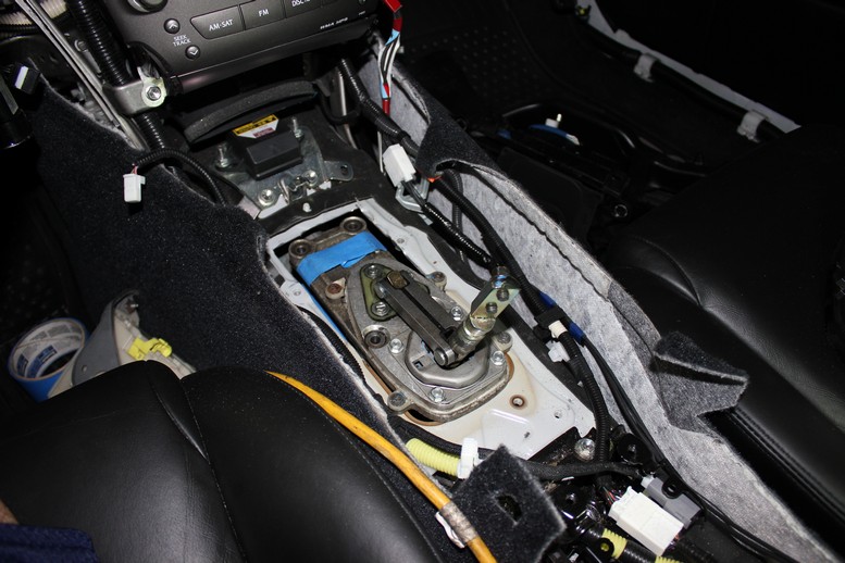
I have 2 options for the shifter, here is the stock Camaro shifter
and here is the GTO shifter (I'll need a little more cutting if I go with this option)
Next on the list is motor mounts. I got the metal and started to draw out some of the parts but haven't cut any metal yet.
Here's the cut up pan. I'll need a oil filter relocation kit since the filter fall right over the back cross member.
And here's a view from under the car
I also got some other parts since my last post
I cut the hole in the firewall for the master cylinder but I still need to modify the clutch pedal before I install the cylinder and pedal.
Last thing I did tonight was cut the center console for the shifter. Here's the first pick if how the shifter location lines up with the stock location
I have 2 options for the shifter, here is the stock Camaro shifter
and here is the GTO shifter (I'll need a little more cutting if I go with this option)
Next on the list is motor mounts. I got the metal and started to draw out some of the parts but haven't cut any metal yet.
06-15-2013, 01:05 AM
#7
Staging Lane
Thread Starter
iTrader: (4)
Join Date: Oct 2011
Location: Jupiter, FL
Posts: 98
Likes: 0
Received 0 Likes
on
0 Posts
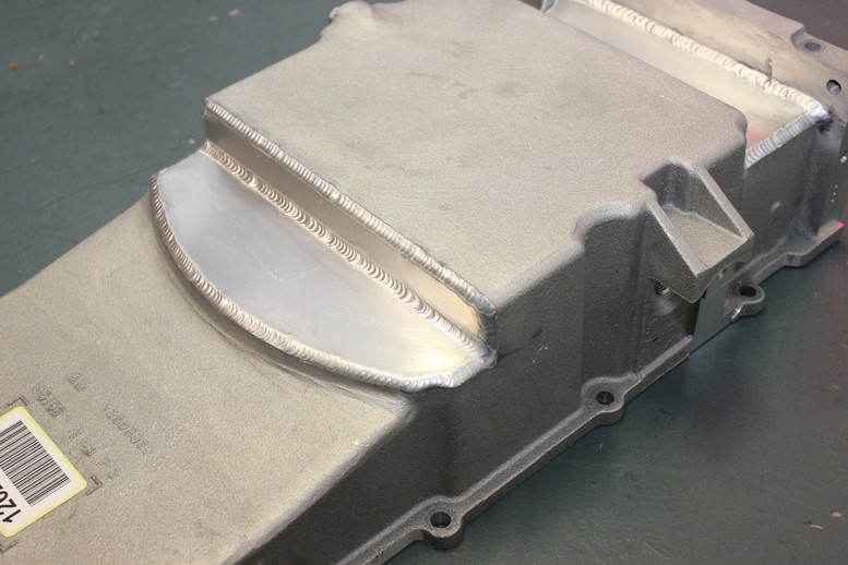
The biggest news for this update are that my motor mounts, transmission mount, and oil pan are done. Below you can see the finished but not yet painted mounts.
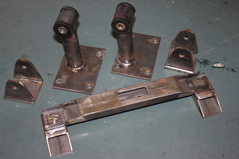
I tacked them up in the car but then had a local shop TIG them. I weld well enough to stick metal together but I don't trust myself with motor mounts or my oil pan. If anyone is looking for a great welder in the West Palm Beach area check out TIG Vision in Riviera Beach, FL. He did great work and charged me $80 for the oil pan and $120 for all the mounts.
Here is a close up of one of the mounts so you can see how clean the welds are.

Here is a pic of the completed oil pan and a close up of the welds.
 .
.
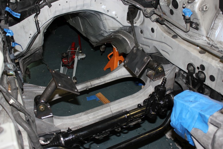
I have also been working on the steering system. I picked up a steering rack from an RX350 which looked it would fit with minimal modifications. However, the inlet ports are on the wrong side of the input shaft so they hit up against the front cross member. I have since swapped it out with one from a Tacoma (I think) and this one looks promising but will need adapters for the outer tie rods. I'll post more on this in the near future.
Here is a shot of the motor mounts mounted to the front cross member, you can also see the RX350 steering rack. In this pic the input shaft to the steering rack is sticking straight up but it will actually be rotated back to align with the current steering shaft. I'll have to fab up some custom mounts.
The last 2 images I'll leave you with are the engine and transmission in their final resting place (even though they will probably come out and back in about 5 more times during the swap)
Next on the list is sorting out the steering situation, working on the clutch pedal mods and clutch master cylinder installation, and measuring for the drive shaft. I'll keep you all posted. Thanks for staying tuned in.
I tacked them up in the car but then had a local shop TIG them. I weld well enough to stick metal together but I don't trust myself with motor mounts or my oil pan. If anyone is looking for a great welder in the West Palm Beach area check out TIG Vision in Riviera Beach, FL. He did great work and charged me $80 for the oil pan and $120 for all the mounts.
Here is a close up of one of the mounts so you can see how clean the welds are.
Here is a pic of the completed oil pan and a close up of the welds.
.I have also been working on the steering system. I picked up a steering rack from an RX350 which looked it would fit with minimal modifications. However, the inlet ports are on the wrong side of the input shaft so they hit up against the front cross member. I have since swapped it out with one from a Tacoma (I think) and this one looks promising but will need adapters for the outer tie rods. I'll post more on this in the near future.
Here is a shot of the motor mounts mounted to the front cross member, you can also see the RX350 steering rack. In this pic the input shaft to the steering rack is sticking straight up but it will actually be rotated back to align with the current steering shaft. I'll have to fab up some custom mounts.
The last 2 images I'll leave you with are the engine and transmission in their final resting place (even though they will probably come out and back in about 5 more times during the swap)
Next on the list is sorting out the steering situation, working on the clutch pedal mods and clutch master cylinder installation, and measuring for the drive shaft. I'll keep you all posted. Thanks for staying tuned in.
Trending Topics
06-15-2013, 01:06 AM
#8
Staging Lane
Thread Starter
iTrader: (4)
Join Date: Oct 2011
Location: Jupiter, FL
Posts: 98
Likes: 0
Received 0 Likes
on
0 Posts
I'm still battling the steering situation but I am making some progress on the throttle and the clutch. I needed a 3 inch jog in the clutch pedal so I cut my pedal in half and made a jog. It's a little overkill with the 3/4" aluminum plate but I had a small piece laying around and didn't want to pay a machine shop to make such a simple piece. I'll probably paint it up black but I am considering having it welded in addition to the bolts so I'll wait until make my decision on the weld before I paint it.

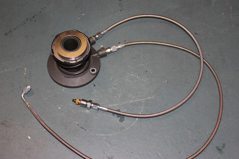
I also added a remote bleeder, AN adapter, and the hydraulic line to the clutch throw out bearing. Nothing crazy but I like the stainless braided cables so I though it was picture worthy.
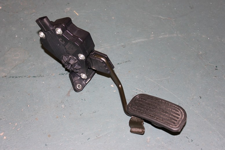
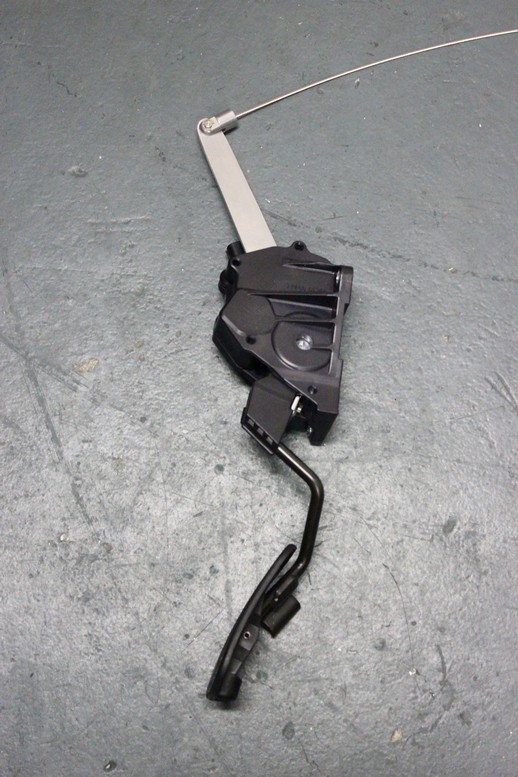
Next was the throttle which I completely forgot about until about 2 weeks ago when I was under the dash and saw the electronic pedal. Since there was nothing wrong with the pedal I decided to keep it and attempt to convert it to a drive by cable pedal.
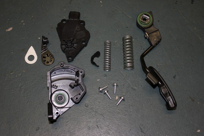
For those of you interested, here is what the inside of the drive by wire pedal looks like.
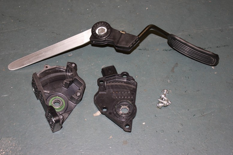
After a little cutting and grinding and a new lever arm, my new drive by cable pedal was complete. I am waiting on drilling the hole for the cable until I get it in the car and mark it.
This is not a great picture but the Lokar stainless braided throttle cable fits very nicely right next to the A/C lines.

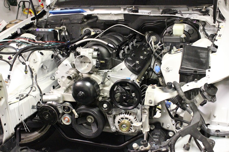
Last thing I did was give the engine bay a bath in preparation for the engine to go in for hopefully the last time (for now) I don't think it will ever be this clean again.
Hopefully my next post will be that of an installed steering rack...
I also added a remote bleeder, AN adapter, and the hydraulic line to the clutch throw out bearing. Nothing crazy but I like the stainless braided cables so I though it was picture worthy.
Next was the throttle which I completely forgot about until about 2 weeks ago when I was under the dash and saw the electronic pedal. Since there was nothing wrong with the pedal I decided to keep it and attempt to convert it to a drive by cable pedal.
For those of you interested, here is what the inside of the drive by wire pedal looks like.
After a little cutting and grinding and a new lever arm, my new drive by cable pedal was complete. I am waiting on drilling the hole for the cable until I get it in the car and mark it.
This is not a great picture but the Lokar stainless braided throttle cable fits very nicely right next to the A/C lines.
Last thing I did was give the engine bay a bath in preparation for the engine to go in for hopefully the last time (for now) I don't think it will ever be this clean again.
Hopefully my next post will be that of an installed steering rack...
 06-15-2013, 01:08 AM
#10
Staging Lane
Thread Starter
iTrader: (4)
Join Date: Oct 2011
Location: Jupiter, FL
Posts: 98
Likes: 0
Received 0 Likes
on
0 Posts
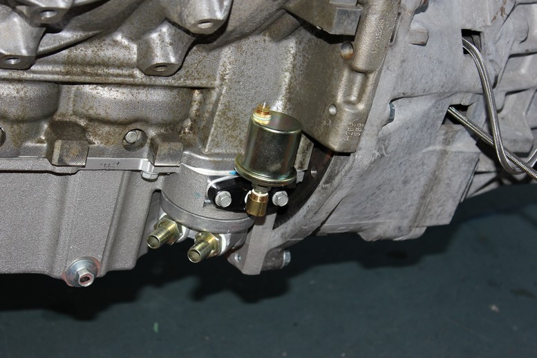
I figured it was time to get the engine into it's final resting place so I had to do some prep work. First was some pre-wiring in the hard to reach places including 3 connections on the transmission. The oil pan notch for the lower cross member blocked access to the oil filter so I had to get an oil filter relocation kit. And lastly the oil pressure gauge sending unit is also in a hard to reach place so I installed that as well. Here's a shot of the pressure sensor and oil filter cap.
There were probably some more connections I would have made but I am very impatient so the engine went in next.
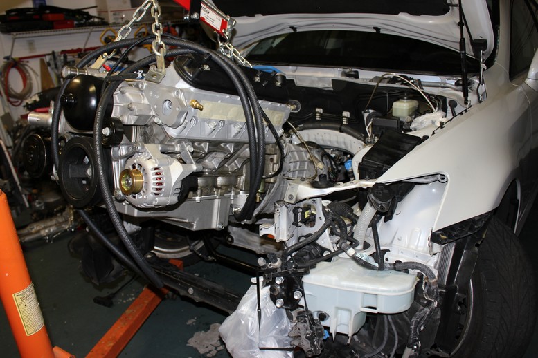
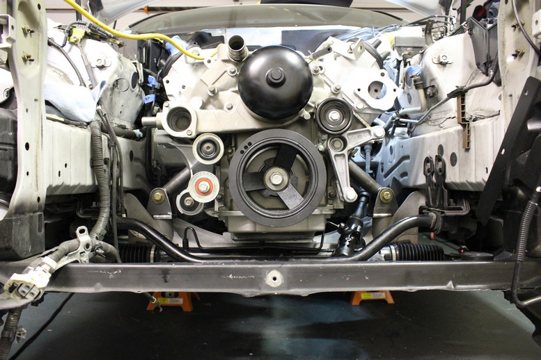
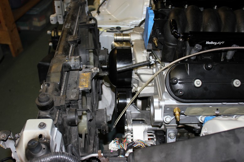
I couldn't help but put the intake manifold on and then the radiator for a fit check. There is on plastic tab on the radiator that will need to be cut off but other than that it fits fine. I'll keep a close eye on engine temperature, especially during the summer in Florida, to see if the stock radiator is capable of cooling the engine.
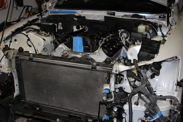
Side shot of the radiator clearance
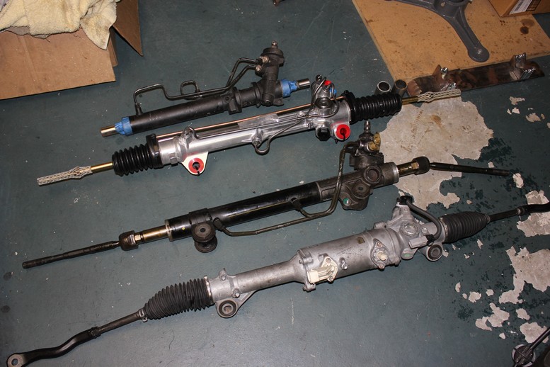
And now the steering saga continues. Here is my current collection of steering racks. Starting at the top is a Mazda 626 rack, then an AGR performance Mustang rack, then a Toyota Tacoma, and finally at the bottom the IS250 electric rack.
Prior to buying the AGR performance rack, I pretty much had the Mazda rack installed. It wasn't until the last minute that I realized that the input shaft came in above the rack therefore turning the wrong direction. A very frustrating moment but it led me to the AGR rack which looks awesome and I think I'll be very happy with.
Here is a shot of the 2 old mounting holes on the lower front cross member.
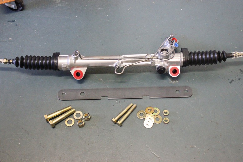
Here is the final bracket and hardware
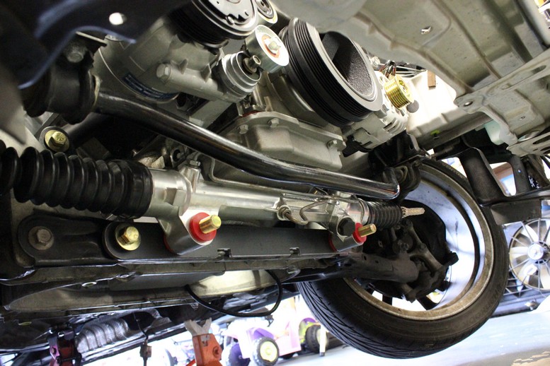
And finally the installed rack (well almost installed. It still needs paint and nuts. This was a very victorious moment for me after all that have gone though with the steering system.
There were probably some more connections I would have made but I am very impatient so the engine went in next.
I couldn't help but put the intake manifold on and then the radiator for a fit check. There is on plastic tab on the radiator that will need to be cut off but other than that it fits fine. I'll keep a close eye on engine temperature, especially during the summer in Florida, to see if the stock radiator is capable of cooling the engine.
Side shot of the radiator clearance
And now the steering saga continues. Here is my current collection of steering racks. Starting at the top is a Mazda 626 rack, then an AGR performance Mustang rack, then a Toyota Tacoma, and finally at the bottom the IS250 electric rack.
Prior to buying the AGR performance rack, I pretty much had the Mazda rack installed. It wasn't until the last minute that I realized that the input shaft came in above the rack therefore turning the wrong direction. A very frustrating moment but it led me to the AGR rack which looks awesome and I think I'll be very happy with.
Here is a shot of the 2 old mounting holes on the lower front cross member.
Here is the final bracket and hardware
And finally the installed rack (well almost installed. It still needs paint and nuts. This was a very victorious moment for me after all that have gone though with the steering system.
06-15-2013, 04:14 AM
#11


Great progress so far and nice work. One thing I would do if I were you would be to box your steering rack to give it some more strength. I would add a piece to the bottom and then bring tabs up for the front side of the bolts. Basically building a "U" channel that the rack would drop into, then bolt it to the sub-frame.
 06-15-2013, 07:54 AM
#13
Staging Lane
Thread Starter
iTrader: (4)
Join Date: Oct 2011
Location: Jupiter, FL
Posts: 98
Likes: 0
Received 0 Likes
on
0 Posts
Great progress so far and nice work. One thing I would do if I were you would be to box your steering rack to give it some more strength. I would add a piece to the bottom and then bring tabs up for the front side of the bolts. Basically building a "U" channel that the rack would drop into, then bolt it to the sub-frame.


 06-16-2013, 09:37 PM
#19
Staging Lane
Thread Starter
iTrader: (4)
Join Date: Oct 2011
Location: Jupiter, FL
Posts: 98
Likes: 0
Received 0 Likes
on
0 Posts
I guess the theme of the night is brackets. I started with the throttle cable bracket which I fabricated out of a piece of extruded aluminum I had laying around from a pool enclosure. I cut a piece out, drilled a few holes, ground down the white powder coating and ended up with a decent looking throttle cable bracket and saving about $50.
Here is a pic of the bracket next to the material that it started out as
And another one of it installed on the car
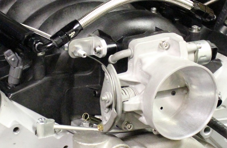
Next I moved onto the fuel pressure regulator bracket which I made out of some .050" stainless sheet.
Here is a pic off the car
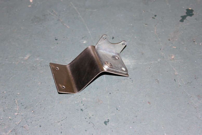
And another one of the finished product
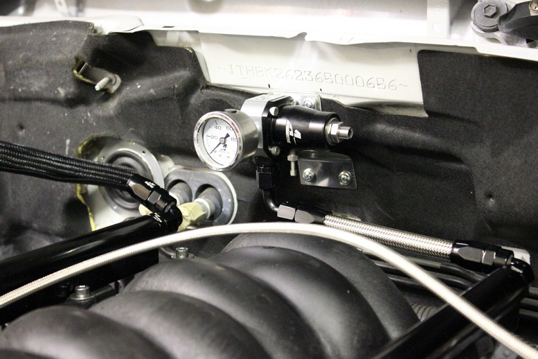
I picked up some nicer looking stainless hardware today that I'll put on during the next session.
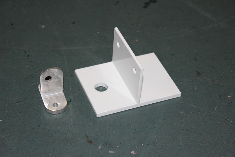
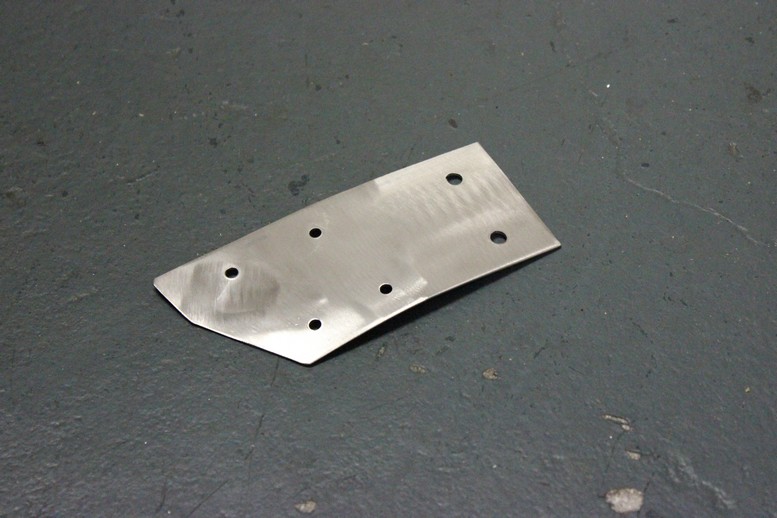
Last bracket of the night was the clutch master cylinder reservoir. Here it is off the car.
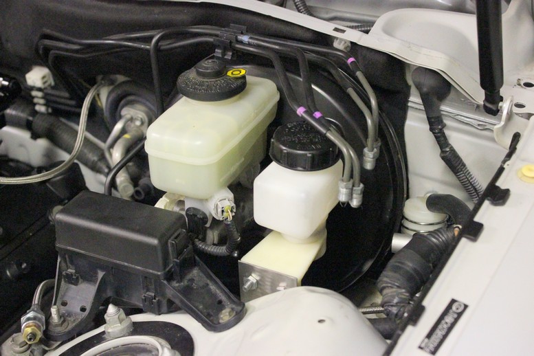
And now installed, I also have some nicer hardware for this one as well
This was what the assemble accelerator pedal looked like right before installed it
Here's how I left her at the end of the night. I actually got the wiring harness through a grommet that I installed adjacent to the heater core lines. I'll show some better picture when I get into wiring in a few days.
Here is a pic of the bracket next to the material that it started out as
And another one of it installed on the car
Next I moved onto the fuel pressure regulator bracket which I made out of some .050" stainless sheet.
Here is a pic off the car
And another one of the finished product
I picked up some nicer looking stainless hardware today that I'll put on during the next session.
Last bracket of the night was the clutch master cylinder reservoir. Here it is off the car.
And now installed, I also have some nicer hardware for this one as well
This was what the assemble accelerator pedal looked like right before installed it
Here's how I left her at the end of the night. I actually got the wiring harness through a grommet that I installed adjacent to the heater core lines. I'll show some better picture when I get into wiring in a few days.

