
Transmission Fused Pink wire?
 10-08-2013, 06:10 PM
#1

Pink fused ign wires I have..
Pink- Bank 1 and Bank 2 (Injectors)
Pink- Bank 1 and Bank 2 (Coils)
Pink- Bank 1 and Bank 2 (O2 Sensor)
Pink- Maf wire
Pink- PCM Fused Ignition (pin# 19 C1 BLUE)
There should be a Pink- Fused Transmission wire (from pin#75 C1 BLUE)
Trying to figure out whats going on with the Pink trans wire that needs fused Ignition.
On the transmission connector I have Pin E, which is Circuit number 1020, goes to pin# 75 @ C1 Blue PCM connector. On LT1SWAP.com it says that pin# 75 is the wire I'm looking for, yet this wire leads to the trans connector.
So should I add another pink wire to the one that runs from the trans to pin 75 on the c1 blue and splice into it? Then this splice run to the fuse block under the hood?
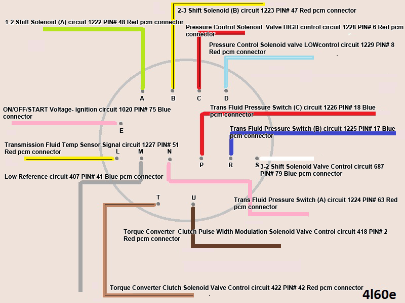
Diagram I made for trans connector.
Note* Pin E
Pink- Bank 1 and Bank 2 (Injectors)
Pink- Bank 1 and Bank 2 (Coils)
Pink- Bank 1 and Bank 2 (O2 Sensor)
Pink- Maf wire
Pink- PCM Fused Ignition (pin# 19 C1 BLUE)
There should be a Pink- Fused Transmission wire (from pin#75 C1 BLUE)
Trying to figure out whats going on with the Pink trans wire that needs fused Ignition.
On the transmission connector I have Pin E, which is Circuit number 1020, goes to pin# 75 @ C1 Blue PCM connector. On LT1SWAP.com it says that pin# 75 is the wire I'm looking for, yet this wire leads to the trans connector.
So should I add another pink wire to the one that runs from the trans to pin 75 on the c1 blue and splice into it? Then this splice run to the fuse block under the hood?
Diagram I made for trans connector.
Note* Pin E
 10-08-2013, 08:47 PM
#2

Not realy following you. There shouldn't be a fused wire from tje PCM to the transmission connector. You should have a pink from a fused ignition source to the transmission and also an ignition wire powering up the PCM at pin 75, so just power them both off the same wire.
Last edited by ls1nova71; 10-08-2013 at 09:05 PM.
10-08-2013, 09:08 PM
#3

This is the 4l60e connector, goes from here straight to PCM. There is no loose wire to send to the computer.
Note the 1020 Circuit Number, I see on the C2 UNDER HOOD FUSE Block 1020 Circuit also goes to Pins E2 and F2 of the original fuse panel connector, then it also seems to somehow route to old C100 connector on Pin C
I don't remember the wire having a inline splice through the harness, I assume it just split off at the fuse block terminals, and then to the C100 etc I guess. That's why I'm wondering if I should just splice off that pink wire from the trans connector that goes to pin 75 on the C1 blue connector and then I will have my pink wire that needs to goto the new stand alone fuse panel for ign supply.
Last edited by BOXCHEV; 10-08-2013 at 09:26 PM.
10-09-2013, 09:47 AM
#4
You are correct, they should both have power. The factory powers them both off the D3 circuit (ign 0 Fuse). The F2 and E2 wires are jumped in the original fuse block. So do what you were saying and tap into the wire and hook ignition power to it and you'll be good to go. Don't know how your wire wasn't loose though, I've never had this problem nor heard of anybody else having it. Did you mod the harness? Is it aftermarket?
10-09-2013, 12:09 PM
#5
It is a factory 99-02 truck harness. The harness was supposed to be for a 4l60e, however I found out it was a 4l80e harness.
I asked the person who sold me the harness to either send me a 4l60e trans connector or refund me the amount to buy one. So yeah I had to convert it from 4l80e to 4l60e for my application.
4L80E = 11 wires
4L60E = 13 wires, so I had to add some pins/wire to the PCM connector.
Ive modded the harness myself. Everything from the C100, C2 Fuse block connector etc, all wires were labeled according to their pin position before I cut anything. I also did this some time ago so this is probably why I cant exactly remember everything, perhaps some wires got lost in the box of unneeded wires I deleted from the PCM.
I went with a car intake, and needed to change the harness layout and re-route the harness so it was inside the cabin. So I de-pinned the C1 Blue/C2 Red connectors, again I labeled all wires to their appropriate pin# and if it came from C1 or C2 before removing them.
Plugged in each connector to where they needed to go on the motor, then routed how I wanted, and extended and shorten wires from there and plugged each pin back into the PCM connectors one at a time.
Any wire that got cut, got labeled on both ends so there was no confusion as to what needed to be soldered to what.
I'm done with everything expect the Orange wires for Batt, then blue and green wires for electric fans. I have my check engine light, tach wire, brake pedal switch wire etc off to the side because those will be going back into the cabin of the car to either power source in the car or to digital gauge brain.
Are there typically ground points on the actual motor (iron block) and transmission?
The ground points that used to be on the back of the heads I moved to the front of the heads. with my motor sitting back against the firewall it was a bad spot if I needed to access them. So grounds on the heads got moved to the front.
I feel like I should add more grounds before I complete the ground harness.
10-19-2013, 06:00 PM
#6
Bump!
Any second opinions on the fused pink trans wire?
I pretty much finished my grounds, there are two runs of 12ga wire with crimped ring terminals grounded on front side of heads, then they split back into 1 length of 12ga wire where the rest of the needed ground wires splice into it, then the rest of the 12ga routes back by pcm connectors where I'm gonna crimp another ring terminal and ground it to car body just because. Think I will add another to the engine block.
Last edited by BOXCHEV; 10-19-2013 at 06:19 PM.
10-19-2013, 07:02 PM
#7
Just splice the trans ignition into the engine sensor circuit.
Bill
Bill
__________________
Standalone LS Swap Harnesses IN STOCK!
LSX, LTX Stand alone swap harnesses. S10 LSX conversion PLUG AND PLAY harnesses, 24x conversion PLUG AND PLAY harnesses. LT1 to LSX PLUG AND PLAY Harnesses.
sales@bp-automotive.com
www.bp-automotive.com
1-888-467-4491
Standalone LS Swap Harnesses IN STOCK!
LSX, LTX Stand alone swap harnesses. S10 LSX conversion PLUG AND PLAY harnesses, 24x conversion PLUG AND PLAY harnesses. LT1 to LSX PLUG AND PLAY Harnesses.
sales@bp-automotive.com
www.bp-automotive.com
1-888-467-4491
Trending Topics
 03-15-2017, 05:25 PM
#12
Registered User

Join Date: Mar 2017
Posts: 4
Likes: 0
Received 0 Likes
on
0 Posts
I have a 99 5.7 with a tcc circuit open code P0740. From the Tranny fuse (#20 Interior box), goes two pink wires. One of which, goes to pin E on my 4L80E, (Powering the solenoids) and the other unknown.. And have continuity between TCC solenoid and ECM C2 Red pin #7 (TCC Ground Control). So therefore I have no opening in my circuit and have already replaced the ECM, IGN switch and TCC. Still stuck in 3rd gear limp mode. Weird though, I have continuity from Pin E on tranny to C3 Clear/Grey plug pin #21 (Orange 12v battery feed).. Not sure where that other pink wire should be going, or why it says my circuit is open, when it is in fact not. (With my MODIS I can manually engage the tcc and it does in fact engage) I'm lost as to whether I need to jump a 12V to somewhere on the ECM to make it think the circuit is closed..
Last edited by Jsimo23; 03-15-2017 at 05:37 PM.