
1967 Cougar build (over 500 pictures and videos)
 04-12-2015, 06:01 PM
#341
TECH Senior Member
Thread Starter
iTrader: (7)

Today was another gorgeous day and I managed to get a few things done. I was going to use spray on bedliner for the tank, but when I got to the parts store I saw that the 3M rubberized undercoating was 2 for 1, so I went with that. It went on easy and looks much better than having a silver tank visible from the back. Sorry, forgot to take a picture...LOL
I needed to wrap up all the brake plumbing, and install a new rubber flex hose that goes from the rear end to the chassis. Unfortunately, when I started to remove the fittings from the rear distribution block, the fittings were rusted solid to the lines, and twisted right off. I decided that instead of having the same thing happen with the rear feed line that goes to the flex hose, I would cut the line, and make a new short line and put them together with a brass union.

Since both sides of the rear axle brake lines were totally shot, I just made new ones. I thought about ordering pre-bent lines, but I had plenty of the 3/16" NiCopp and fittings, so I made some.


Not exactly "factory correct" bends, but good enough for this project.
Andrew
I needed to wrap up all the brake plumbing, and install a new rubber flex hose that goes from the rear end to the chassis. Unfortunately, when I started to remove the fittings from the rear distribution block, the fittings were rusted solid to the lines, and twisted right off. I decided that instead of having the same thing happen with the rear feed line that goes to the flex hose, I would cut the line, and make a new short line and put them together with a brass union.
Since both sides of the rear axle brake lines were totally shot, I just made new ones. I thought about ordering pre-bent lines, but I had plenty of the 3/16" NiCopp and fittings, so I made some.
Not exactly "factory correct" bends, but good enough for this project.
Andrew

 04-13-2015, 01:32 PM
#344
I used that same Ridgid tool for my fuel and power steering lines. Worked great. Tipsy McStagger is lucky he found out about the remote bleeder fiasco before installation.
04-13-2015, 03:03 PM
#345

I have the Speedway bleeder kit (5151399-36) sitting on the shelf waiting for installation. I'd rather not have any leaks if they can be avoided.
Can you list the part number(s) of the parts you bought to rectify the crush washer situation?
Thanks.
Tipsy
Can you list the part number(s) of the parts you bought to rectify the crush washer situation?
Thanks.
Tipsy
LS1 & LT1 T56 Release Bearing to AN3 Line Fitting
and
GM Metric Caliper Fitting, 10mm - 1.5 to -3 AN, Male Adapter Connector
Turns out I didn't need them, after paying overnight on Saturday delivery charges. Ugh...
If those are what you need, mine are still sealed in the box from Speedway, and I'd prefer to sell them than sit on them. Drop me a PM and perhaps we can strike up a deal.
04-13-2015, 03:07 PM
#346
TECH Senior Member
Thread Starter
iTrader: (7)
I'm not sure exactly what you are looking for, but I purchased 2 pieces from Speedway a few weeks ago that I'm not using which may be what you need.
LS1 & LT1 T56 Release Bearing to AN3 Line Fitting
and
GM Metric Caliper Fitting, 10mm - 1.5 to -3 AN, Male Adapter Connector
Turns out I didn't need them, after paying overnight on Saturday delivery charges. Ugh...
If those are what you need, mine are still sealed in the box from Speedway, and I'd prefer to sell them than sit on them. Drop me a PM and perhaps we can strike up a deal.
Andrew
04-13-2015, 10:28 PM
#348
TECH Senior Member
Thread Starter
iTrader: (7)
This evening I decided to grow a pair and tackle the installation of the TCP rack. The stock Cougar/Mustang steering looks like this:

The original set-up is straightforward, rear steer, with the a manual steering box bolted to the side of the driver's side frame rail. The position of the steering box is especially problematic for header and general exhaust clearance, not matter what engine is being used.
First thing to do is get it all out of there. The easiest way to get it out is to take it all out as a single unit. I used a fork to pop the outer tie rods loose. This job is made much easier by a 12 pound sledge hammer. The idler arm is held to the frame by couple of bolts that can be easily accessed through the fender well, while the steering box is help on by 3 bolts accessed from the driver's side wheel well. Once loose, it all falls out in one piece.

Part of the TCP rack kit is a concentric bolt eliminator kit. This part is critical, because two of the brackets that hold the rack in place hang on the ends of these bolts. I noted the location of the bolts before I took them off and I chose holes that put the bolt in approximately the same location, to keep the alignment approximately the same.
Back of the passenger side.

Front of the passenger side.
Here is the bracket that attaches to the passenger side (sorry about the heater hoses...)

And the driver's side...

Those two brackets are slotted (up and down) so that they can be positioned in such a way at to keep the rack straight. This is critical otherwise the mounts will try to bend the rack and put it in a bind.
The driver's side bracket is already attached to the rack. In the instructions it says to mock everything up and see if shims are needed. I determined that using the thicker shims would allow all 4 bracket to line up properly (if you are installing the rack, make sure you follow the directions!)

Once all the collars for the brackets are tight, all four of the rack brackets are tightened down in sequence with careful attention given to make sure that none of the brackets are trying to put a strain on the rack tube. Once I tightened everything down, I could easily turn the rack shaft by hand, and there was no bind or notchieness, which means there is no strain on the rack.

Overall, a very well thought out kit and the installation is very straightforward. Mine was made a lot easier because I didn't have an engine installed, so I did much of the work sitting inside the engine compartment. While this made life a lot easier, it wouldn't be bad to do from the underside, especially if you got a buddy to help (I didn't).
Here you can see the much improved exhaust room.

Money well spent!
Andrew
The original set-up is straightforward, rear steer, with the a manual steering box bolted to the side of the driver's side frame rail. The position of the steering box is especially problematic for header and general exhaust clearance, not matter what engine is being used.
First thing to do is get it all out of there. The easiest way to get it out is to take it all out as a single unit. I used a fork to pop the outer tie rods loose. This job is made much easier by a 12 pound sledge hammer. The idler arm is held to the frame by couple of bolts that can be easily accessed through the fender well, while the steering box is help on by 3 bolts accessed from the driver's side wheel well. Once loose, it all falls out in one piece.
Part of the TCP rack kit is a concentric bolt eliminator kit. This part is critical, because two of the brackets that hold the rack in place hang on the ends of these bolts. I noted the location of the bolts before I took them off and I chose holes that put the bolt in approximately the same location, to keep the alignment approximately the same.
Back of the passenger side.
Front of the passenger side.
Here is the bracket that attaches to the passenger side (sorry about the heater hoses...)
And the driver's side...
Those two brackets are slotted (up and down) so that they can be positioned in such a way at to keep the rack straight. This is critical otherwise the mounts will try to bend the rack and put it in a bind.
The driver's side bracket is already attached to the rack. In the instructions it says to mock everything up and see if shims are needed. I determined that using the thicker shims would allow all 4 bracket to line up properly (if you are installing the rack, make sure you follow the directions!)
Once all the collars for the brackets are tight, all four of the rack brackets are tightened down in sequence with careful attention given to make sure that none of the brackets are trying to put a strain on the rack tube. Once I tightened everything down, I could easily turn the rack shaft by hand, and there was no bind or notchieness, which means there is no strain on the rack.
Overall, a very well thought out kit and the installation is very straightforward. Mine was made a lot easier because I didn't have an engine installed, so I did much of the work sitting inside the engine compartment. While this made life a lot easier, it wouldn't be bad to do from the underside, especially if you got a buddy to help (I didn't).
Here you can see the much improved exhaust room.
Money well spent!
Andrew
04-14-2015, 03:32 AM
#349

Andrew,
There wasn't any crossmember there stock? Not like a typical GM. Where is that Cougar from? Thats one clean car !!!
There wasn't any crossmember there stock? Not like a typical GM. Where is that Cougar from? Thats one clean car !!!
04-14-2015, 12:17 PM
#350
TECH Senior Member
Thread Starter
iTrader: (7)
The car was originally purchased by a man that lived in Willow Springs, IL, but was subsequently purchased around 1970 by the man that I got it from. I don't think that is has seen much of Illinois winters, hence it's relatively rust free state.
Andrew
 04-14-2015, 02:48 PM
#352
TECH Senior Member
Thread Starter
iTrader: (7)
That's where the inner tie rods attach. If you compare the new rack and the old steering, you will see that the inner tie rods are in the same place. That whole back bracket moves. This is critical for proper bump steer. TCP clearly thought about all this.
Andrew
Andrew
04-16-2015, 07:18 PM
#353
TECH Senior Member
Thread Starter
iTrader: (7)
Nothing major to report, except that this evening I installed the proper fuel level sending unit to work with the existing Stewart Warner fuel level gauge.
Tomorrow is a big day, my buddy Shaun is coming up from Janesville and the plan is to install the engine to determine its new position now that the TCP rack is installed. Should be a busy and hopefully productive day!
Andrew
Tomorrow is a big day, my buddy Shaun is coming up from Janesville and the plan is to install the engine to determine its new position now that the TCP rack is installed. Should be a busy and hopefully productive day!
Andrew
04-18-2015, 09:09 AM
#354
TECH Senior Member
Thread Starter
iTrader: (7)
Shaun came over yesterday and it was great having him help me. We messed around with the car all day but sadly there isn't much to show for it. Most of the day was spent moving the engine here, there, forward, back, left, right, ugh...Finally we decided that the first thing to do was make the trans crossmember, which will anchor the trans in the rear and make engine placement a little easier.
As Shaun was walking around the garage he looked down at the pile of parts left over from the rack install, and pointed at the front crossmember, and said "what's that?" Light bulbs went off instantly.
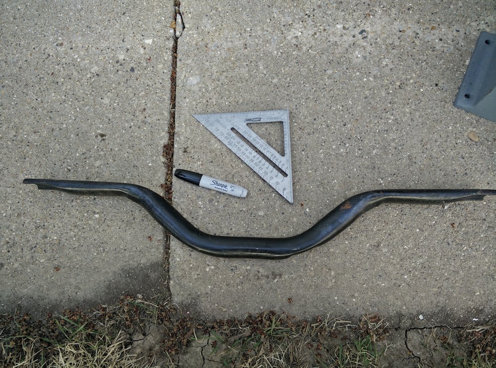
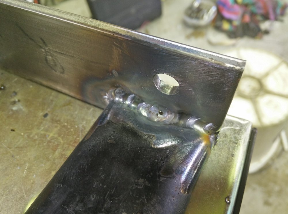
The front crossmember is almost the perfect shape to use as the transmission crossmember. I used a chop saw to cut the end off so that it fits between the frame rails. Then I tacked on some 3/16" plate on either side.
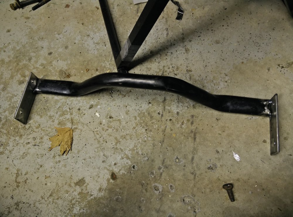
We then drilled the frame rails and made plates for the opposite side to distribute the load so that the bolts don't collapse the frame rails.
It's not quite done, but I will finish it up over the weekend.
This picture was taken just for inspiration, because there is still a lot of work to be done.
Andrew
As Shaun was walking around the garage he looked down at the pile of parts left over from the rack install, and pointed at the front crossmember, and said "what's that?" Light bulbs went off instantly.
The front crossmember is almost the perfect shape to use as the transmission crossmember. I used a chop saw to cut the end off so that it fits between the frame rails. Then I tacked on some 3/16" plate on either side.
We then drilled the frame rails and made plates for the opposite side to distribute the load so that the bolts don't collapse the frame rails.
It's not quite done, but I will finish it up over the weekend.
This picture was taken just for inspiration, because there is still a lot of work to be done.
Andrew
04-18-2015, 05:56 PM
#355
TECH Senior Member
Thread Starter
iTrader: (7)
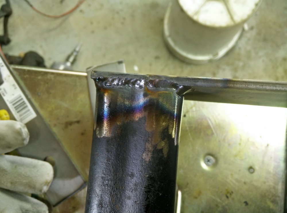
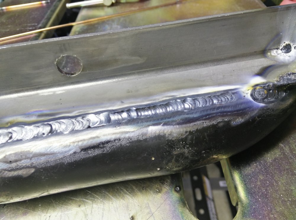
After a long day in the garage yesterday, I really wasn't feeling it today, but I did manage to go out there and finish welding the plates to the trans crossmember.
Not terrible for a newbie...
Andrew
Not terrible for a newbie...
Andrew
04-19-2015, 10:02 AM
#356

3 1/2 weeks till Automotion............Hurry up.......
04-19-2015, 12:05 PM
#357
On The Tree

Join Date: Apr 2011
Location: Vancouver, WA
Posts: 129
Likes: 0
Received 0 Likes
on
0 Posts

Weld in some ferrels/tubes in the frame rails for your tranny mount. Make sure they extend all the way from the inside to the outside of the frame rail. This will strengthen the rails and make it impossible to crush the frame even if you over torque the bolts.
Enjoying your build. Keep up the great work!
Enjoying your build. Keep up the great work!
04-20-2015, 11:14 AM
#358
TECH Senior Member
Thread Starter
iTrader: (7)
Weld in some ferrels/tubes in the frame rails for your tranny mount. Make sure they extend all the way from the inside to the outside of the frame rail. This will strengthen the rails and make it impossible to crush the frame even if you over torque the bolts.
Enjoying your build. Keep up the great work!
Enjoying your build. Keep up the great work!
What we did do is make a plate that spans across the other side of the trans mount and effectively sandwiches the frame rails. There is no need to over tighten these fasteners, since the bolts practically stay in place on their own because of the weight of the transmission. It'll be fine.
Andrew
04-20-2015, 11:14 AM
#359
TECH Senior Member
Thread Starter
iTrader: (7)
Since I find myself in a position where I have to redo the engine mounts, I figured the best place to start would be positioning the engine where I want it and then use the transmission mount as an anchor point. I made the placement of the transmission crossmember such that making a transmission pad would be straight forward. Using some angle iron, I simply spanned it across the crossmember and tacked it in place. I positioned the pad about 1/4" lower than where I wanted the transmission to finally rest because that gives me a little giggle room, up and down. I will make some shims to put the transmission in it's final location, but as of now the trans mount is holding the engine where I want it to be, front to back, and the the back of the trans is centered in the tunnel.
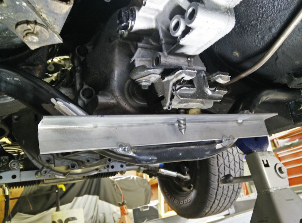
I then fully welded the angle iron along the bottom and also where it meets up with the crossmember on the sides. I think it's way more solid than the original part, which was rather flimsy.
When it comes to working out proper driveline angles, there seems to be a lot of confusion and varying opinion floating around the Internet. The goal of driveline alignment is very straightforward. Under load, the front and rear operating angles must be equal, opposite, and as small as possible (under 3 degrees), but not zero.
This is a basic diagram from Mark Williams that illustrates what I just wrote:

Since I have the transmission where I want it, and I had the front of the engine where I wanted, I could take some simple measurements to see where I was at with this car.
Unfortunately, one of the measurements that is needed is the angle of the driveshaft. Since I don't have one in place, I thought of a simple way that I could approximate the angle. I measured the CV mounting holes diameter on my slip yoke and I did the same for the rear pinion yoke. The measurements were nearly identical, which means that I could run a string from the bottom of the slip yoke to the bottom of the pinion yoke to approximate my driveshaft angle.
I attached the string like this in the front:

In the rear I attached it like this:

The car is on jack stands in the front, but there rear suspension is on the ground. Having the rear suspension loaded and at ride height is imperative to getting the right measurements.
With the string in place, I got my digital angle finder out, and got the following numbers:
Slip yoke: 8.6* down towards the rear (this makes sense since the car is jacked up high in the front)
Driveshaft (string): 8* down towards the rear.
Pinion: 7* up towards the front.
From the above numbers we get the following:
Front operating angle = 8.6 - 8 = .6 degrees
Rear operating angle = 7 - 8 = -1 degree
Going back to our stated goals, we see that this is a pretty good starting point in a static state. Under power, the pinion will want to climb up and so the rear operating angle will decrease as it travels through it's range of motion.
While I don't technically need the CV joints in this application, I still plan on using them to achieve the smoothest driveline that I can. With the 4.33 rear gear and the 27" tires the driveshaft will be spinning at a hair over 4000RPM @ 75 MPH, so it is critical that all the components are running true (as little runout as possible) and that all of the components are balanced as perfectly as possible.
Andrew
I then fully welded the angle iron along the bottom and also where it meets up with the crossmember on the sides. I think it's way more solid than the original part, which was rather flimsy.
When it comes to working out proper driveline angles, there seems to be a lot of confusion and varying opinion floating around the Internet. The goal of driveline alignment is very straightforward. Under load, the front and rear operating angles must be equal, opposite, and as small as possible (under 3 degrees), but not zero.
This is a basic diagram from Mark Williams that illustrates what I just wrote:
Since I have the transmission where I want it, and I had the front of the engine where I wanted, I could take some simple measurements to see where I was at with this car.
Unfortunately, one of the measurements that is needed is the angle of the driveshaft. Since I don't have one in place, I thought of a simple way that I could approximate the angle. I measured the CV mounting holes diameter on my slip yoke and I did the same for the rear pinion yoke. The measurements were nearly identical, which means that I could run a string from the bottom of the slip yoke to the bottom of the pinion yoke to approximate my driveshaft angle.
I attached the string like this in the front:
In the rear I attached it like this:
The car is on jack stands in the front, but there rear suspension is on the ground. Having the rear suspension loaded and at ride height is imperative to getting the right measurements.
With the string in place, I got my digital angle finder out, and got the following numbers:
Slip yoke: 8.6* down towards the rear (this makes sense since the car is jacked up high in the front)
Driveshaft (string): 8* down towards the rear.
Pinion: 7* up towards the front.
From the above numbers we get the following:
Front operating angle = 8.6 - 8 = .6 degrees
Rear operating angle = 7 - 8 = -1 degree
Going back to our stated goals, we see that this is a pretty good starting point in a static state. Under power, the pinion will want to climb up and so the rear operating angle will decrease as it travels through it's range of motion.
While I don't technically need the CV joints in this application, I still plan on using them to achieve the smoothest driveline that I can. With the 4.33 rear gear and the 27" tires the driveshaft will be spinning at a hair over 4000RPM @ 75 MPH, so it is critical that all the components are running true (as little runout as possible) and that all of the components are balanced as perfectly as possible.
Andrew
04-23-2015, 02:37 PM
#360
TECH Senior Member
Thread Starter
iTrader: (7)
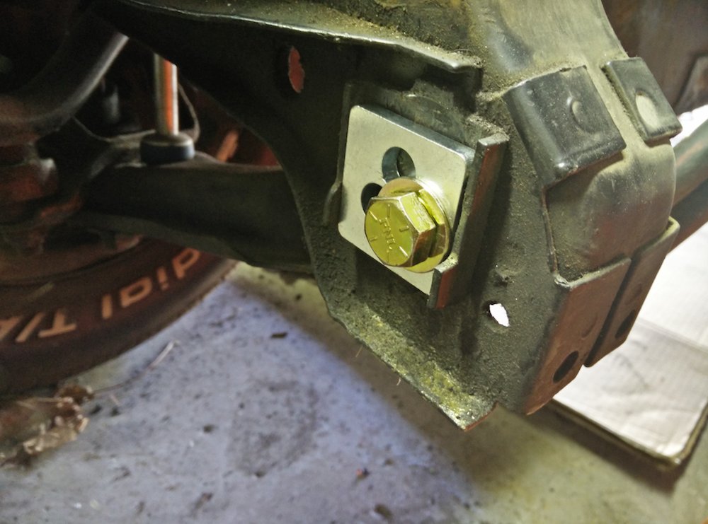
Later today I should have a delivery by FedEx for an experimental set of engine mounts. When I was researching this build I ran across some pictures of people using 4.6L mod motor engine mounts in various, mostly Ford swaps. The mounts look like this.
Right side:

Left side:

The two holes in the front reportedly match the holes in the LSx engine block exactly, while the rear leg needs to only be extended about 1". This should be easily accomplished with a small tab welded to the leg.
I am open to all suggestions as to how I might incorporate these mounts. This is more evidence that the LS is secretly a Ford engine. LOL
Andrew
Right side:
Left side:
The two holes in the front reportedly match the holes in the LSx engine block exactly, while the rear leg needs to only be extended about 1". This should be easily accomplished with a small tab welded to the leg.
I am open to all suggestions as to how I might incorporate these mounts. This is more evidence that the LS is secretly a Ford engine. LOL
Andrew