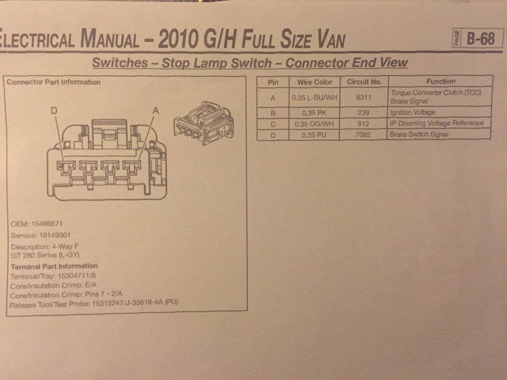
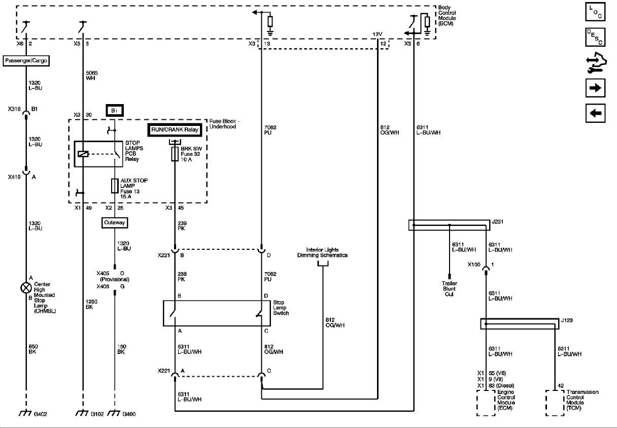
E38 X1 pin 9, TCM pin 42
#1
TCC Brake signal. Do these pins need 12v when brake is applied or not applied???? Getting confliciting info on the net.
Car it is going in has a normally closed brake switch. 12v when brakes not applied.
Close to finishing up the wiring. Don't want to damage anything wired wrong. Thanks!
Car it is going in has a normally closed brake switch. 12v when brakes not applied.
Close to finishing up the wiring. Don't want to damage anything wired wrong. Thanks!
#4
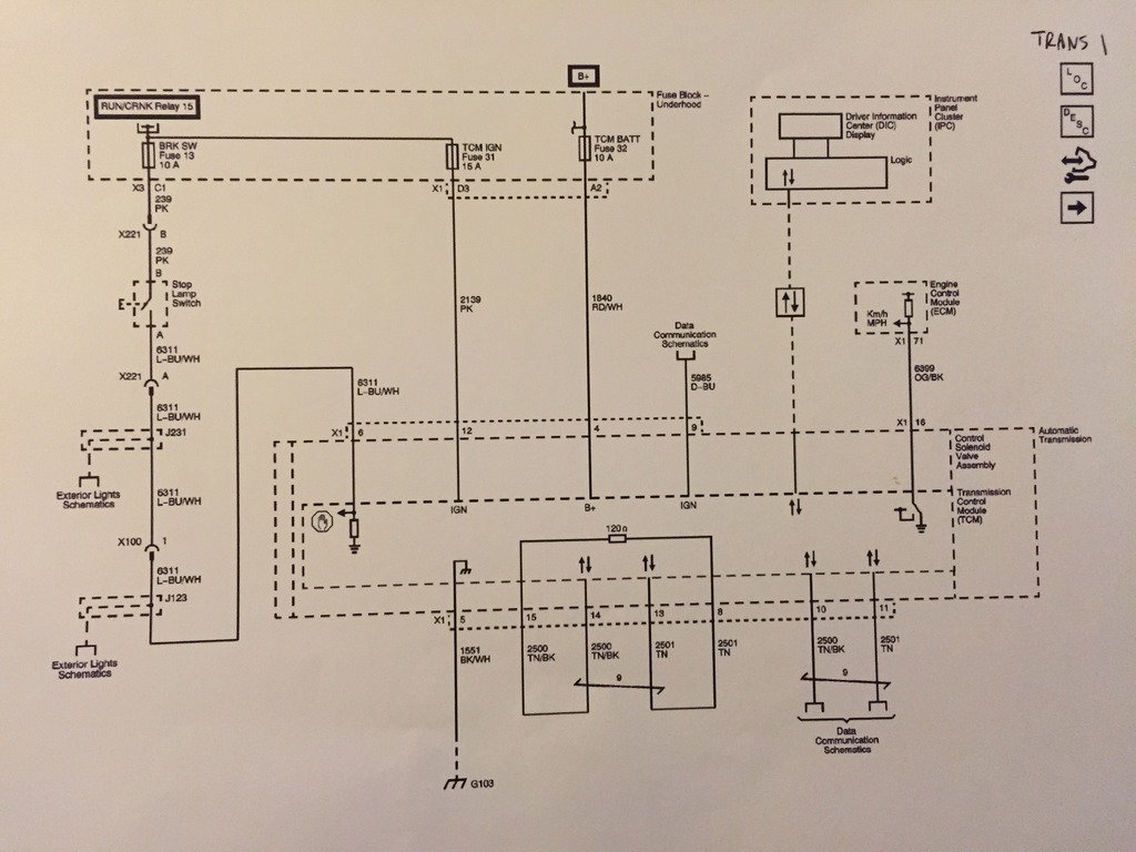
I don't quite remember how I did mine except that I used a brake switch with a double switch. One for the existing brake light circuit and one for the transmission circuit. I believe I wired it like shown in the above schematic but used a resistor to simulate the brake lights(J231, J123).
So the voltage at X1-6 of the 6L80 would be "grounded" through resistor and when the brake is applied the voltage at X1-6 would rise. You will notice an internal resistor at X1-6. I believe and not sure but the part the goes to X1-9 on the ECM is the normally open side of the switch. I don't know if I have helped or hurt.
So the voltage at X1-6 of the 6L80 would be "grounded" through resistor and when the brake is applied the voltage at X1-6 would rise. You will notice an internal resistor at X1-6. I believe and not sure but the part the goes to X1-9 on the ECM is the normally open side of the switch. I don't know if I have helped or hurt.
Last edited by 1989GTA; 07-21-2015 at 08:35 PM.
#6
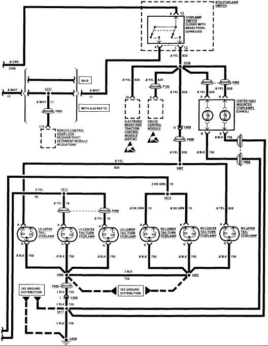
The upper diagram shows the blue white wire (6311 or 8311) going to both the TCM and ECM in the lower right corner. If you did use the bottom diagram it appears that you would have to take the signal off at S238? and run it to both the TCM and ECM. Worst thing that could happen is that it does not work. I don't see you burning anything up.


