Fan relay wiring
#1
TECH Addict
Thread Starter
iTrader: (24)
Join Date: Oct 2006
Location: Webb City, MO...out in the garage
Posts: 2,610
Likes: 0
Received 0 Likes
on
0 Posts

I can't seem to find the exact diagram I need, even though I know it's on here somewhere.
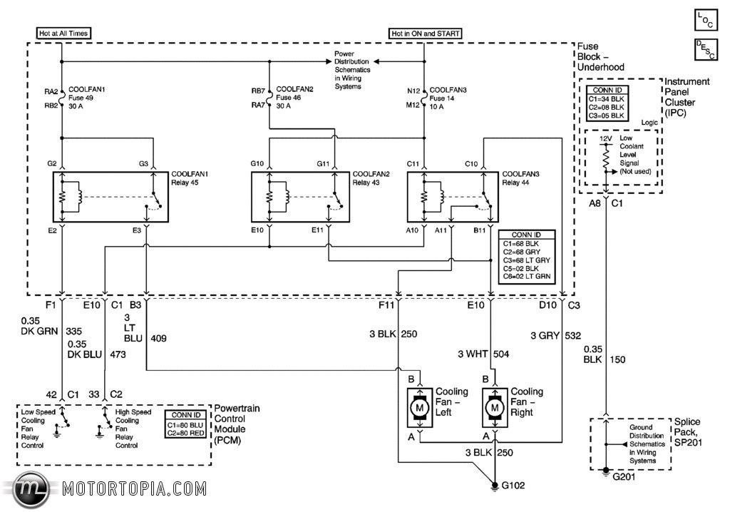
I'm putting the electric fans from a 2000 f body into a 2003 silverado. I have the ecm pinned, I have the fans mounted, and I've enabled the fans in the tune, I just want to know how to wire the relays so the fans work like in a stock vehicle....both kick on low, and both kick on high, not one high/one low. The truck does not have AC so that isn't a factor. Thanks.
I'm putting the electric fans from a 2000 f body into a 2003 silverado. I have the ecm pinned, I have the fans mounted, and I've enabled the fans in the tune, I just want to know how to wire the relays so the fans work like in a stock vehicle....both kick on low, and both kick on high, not one high/one low. The truck does not have AC so that isn't a factor. Thanks.
#4
TECH Addict
Thread Starter
iTrader: (24)
Join Date: Oct 2006
Location: Webb City, MO...out in the garage
Posts: 2,610
Likes: 0
Received 0 Likes
on
0 Posts

I think so, but I'm honestly not too keen on reading factory wiring diagrams. ...how does that correlate to the pins on a relay, i.e. 87, 87A, 30, 86, & 85......I have two 30 amp relays, do I need a third?
#7
TECH Addict
Thread Starter
iTrader: (24)
Join Date: Oct 2006
Location: Webb City, MO...out in the garage
Posts: 2,610
Likes: 0
Received 0 Likes
on
0 Posts

Ok I got a handle on it but have one question, the circled area, what do I do there? Do I omit those wires or what? What is the Power Distribution Schematics in Wiring Systems? I don't understand what I would run a 12v switched and a battery + wire to in this application.
Trending Topics
#8
TECH Resident
Those circled wires will be routed to a 12V+ positive lug either on battery, alternator output or starter lug (large).
Use a voltage drop calculator to determine the necessary wire size: http://www.calculator.net/voltage-drop-calculator.html
Should drop less than 1V, maybe aim for .25V or less.
The wires (your circled arrows) would correspond to relay connection(s) 30 - high current input to relay. 87 is the output. 85 and 86 are the switch triggers where normally 86 is 12V+ and 85 is ground. The computer will output the ground to drive the relay trigger.
Somewhere around 40 amps you may need to step up to a larger (heavier duty) relay than a normal Bosch cube relay.
Doug
#10
TECH Addict
Thread Starter
iTrader: (24)
Join Date: Oct 2006
Location: Webb City, MO...out in the garage
Posts: 2,610
Likes: 0
Received 0 Likes
on
0 Posts

I know how a relay works, I just never can remember how to wire one up, let alone 2 or 3 in series. My only concern at this point is the part of the schematic I circled...it appears to either just be a notation of some sort OR it shows a 12v+ and a 12v switched wire going somewhere.
Either way, I'm going to finish it tonight and I'll post what I did. I think it's right, but I want to make sure.
Either way, I'm going to finish it tonight and I'll post what I did. I think it's right, but I want to make sure.
#11
TECH Resident
I wired up several to drive my fan. One speed only, but I used an AC trinary switch and also have the computer turning it on and off based on engine temps.
I joined the outputs from the fan control relays at a Busbar mounted near the fan. The 12V+ outputs (87) from the relays are connected there. Your relay outputs will connect to the various fan speed inputs.
You could use an isolated busbar(s) to tie the two fans' inputs together.
BTW - the relays look to be wired in parallel, not series. Not trying to knit pick, just use correct terminology. series and parallel electrically are very different.
You could also tie the large, heavy gauge / high amp wire from 12V+ source to a busbar for the multiple relay inputs (on #30 circuits) That might help clean things up. I like Blue Sea Systems marine-grade busbars.
Hope the info helps.
Doug


