
LQ4 into a 3rd Gen/1972 Nova

 11-17-2012, 07:57 PM
#1082
Tony.. Are you mixing up Mark Stielow's "Red Devil" with the famous but much older "Big Red"?
Red Devil (built about 2 years ago)..

Big Red (built in the 90's)...
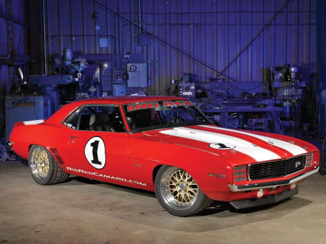
Both cars are wicked-awesome in their own right. Big Red for being the pioneering badass pro-touring car way back when, and beating up on all the exotics on the road courses. Red Devil essentially being the modern-day Big Red, with modern car creature comforts and driveability, with brute power and handling that probably nears that of Big Red. I'd happily own either
Red Devil (built about 2 years ago)..
Big Red (built in the 90's)...
Both cars are wicked-awesome in their own right. Big Red for being the pioneering badass pro-touring car way back when, and beating up on all the exotics on the road courses. Red Devil essentially being the modern-day Big Red, with modern car creature comforts and driveability, with brute power and handling that probably nears that of Big Red. I'd happily own either
of insanity. One of my favorite articles by Ro Mcgonagal when he rode shot-
gun at 200 plus for the Silver State challenge...That car was WAYYYYY
ahead of its time.
11-18-2012, 10:10 PM
#1083
TECH Regular
iTrader: (5)

Join Date: Mar 2010
Location: Vancouver area, West coast Canada
Posts: 401
Likes: 0
Received 29 Likes
on
19 Posts

Goodies! Also got fronts but they got sent with the wrong springs, so can't mount them for good yet, which is ok because I need to cycle thru the front suspension to measure bumpsteer as well as establish the new droop travel at my desired rim height, since these have a shorter stroke than the QA1 coilovers I previously had. Also got some power steering A-body steering arms which are shorter and don't drop, so am going to cycle thru the suspension and measure bump, and relocate the inner tie rod mounting holes on the drag link to minimize bumpsteer. Will report back
11-19-2012, 04:26 AM
#1084
With the extra weight of an iron block, and the turbo setup, the springs were under-sprung at 450 lb/in, and the rebound clicks were almost maxed-out ( 20ish out of 24 clicks i think?) so a stiffer spring would've been demanding a LOT from the rebound circuit to control. plus in the rear I was also oversprung at 200lb/in i think, so instead of already spending a couple hundy $$ on springs.. just upgrade the shocks w/ closer spring-rate springs at the same tiem. I got a ride in a Nova with single-adjust Ridetech coils front/rear and it was pretty impressive. Same springrates I've ordered and it was the perfect combo of firm for handling yet not overly-harsh for bumps..
 11-19-2012, 11:15 AM
#1086
For sway bar, I'm going to get 1.25" OD by 0.125" wall mild steel tube, weld 4-bolt flanges on the end, and heat/bend my own 3/8" end plates, making them hug the frame rails as much as possible. This is still up in the air regarding necessity.. first need to mount the tire and mock everything up, and the UCA's are for sure going to be the first & biggest clearance issue. Thinking of selling my standard UCA's and going hi-clearance ones. If I don't, then I have nowhere near the clearance needed, so can kiss turning radius goodbye, which would essentially axe this whole tire-widening project. In the end, I want this to be a no-compromise driver, so turning radius is part of the overall package.
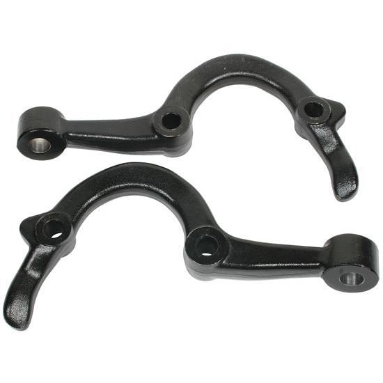
Looking at the TruTurn for a very long time, the steering arms look damn near identical to the A-body steering arms, if not the exact same, altho Ridetech claims they're "made to spec". Also looking at the TruTurn spindles, they are the same variety as the iron 2" drop spindles that are everywhere on ebay, albeit with a 1.75" higher upper ball joint. from much eyeball-engineering, it really looks like the steering arm mount holes are the same between the TruTurn spindles and the other drop spindles, which means that the steering arm holes are kept in the same location relative to the wheel bearing, just moved up the 2" [drop] on the spindle. Since the steering arms also move the outer tie rod end up ~2", and the inner tie rod is moved up ~2" on the drag link, essentially the entire tie rod assembly is simply moved up 2", so it doesn't seem like there's any real crazy length change/angle change, rocketsurgery science behind it. That being said, I still intend on measuring every current link geometry and computing the theoretical camber gain/bump during full droop/bump, to double-check.
Looking at the TruTurn for a very long time, the steering arms look damn near identical to the A-body steering arms, if not the exact same, altho Ridetech claims they're "made to spec". Also looking at the TruTurn spindles, they are the same variety as the iron 2" drop spindles that are everywhere on ebay, albeit with a 1.75" higher upper ball joint. from much eyeball-engineering, it really looks like the steering arm mount holes are the same between the TruTurn spindles and the other drop spindles, which means that the steering arm holes are kept in the same location relative to the wheel bearing, just moved up the 2" [drop] on the spindle. Since the steering arms also move the outer tie rod end up ~2", and the inner tie rod is moved up ~2" on the drag link, essentially the entire tie rod assembly is simply moved up 2", so it doesn't seem like there's any real crazy length change/angle change, rocketsurgery science behind it. That being said, I still intend on measuring every current link geometry and computing the theoretical camber gain/bump during full droop/bump, to double-check.
11-19-2012, 01:50 PM
#1088
Did you calibrate your eyecrometer and unit test your suspension dynamics brainware before making that assessment? Whenever you get to that project, you might consider adjustable tie rod ends on either inside or outside depending on what you come up with for a center link. That way if you get it wrong you have some adjustment. For example:
They make other ones that adjust on the opposite side depending on how/where you need clearance. you can also get ones that use spacers instead of nuts for finite adjustment if you don't like continuous.
Put me in line for the takeoffs. Seriously (assuming the price & shipping are reasonable)
They make other ones that adjust on the opposite side depending on how/where you need clearance. you can also get ones that use spacers instead of nuts for finite adjustment if you don't like continuous.
Put me in line for the takeoffs. Seriously (assuming the price & shipping are reasonable)
11-19-2012, 02:17 PM
#1089
joe, are you CADing any of this up at all, aside from some of the stuff you designed for your swap? I think it would be pretty awesome to design a model of the car to essentially test potential chassis/suspension changes beforehand. sadly, I'm not in the design side of things, so I have to rely on others to translate my designs onscreen (since they can accomplish in less than an hour what takes me a day).
edit: clint, don't forget he's in america's tuke, so shipping over the border will probably be expensive.
edit: clint, don't forget he's in america's tuke, so shipping over the border will probably be expensive.
11-19-2012, 02:29 PM
#1090
Haha I don't have a calibration block for my eyes, but I've been doing a lot of staring, so maybe things are starting to be seen wonky haha.
I already have those tapered studs, and also got a tapered reamer so that I can use nice Moog tie rods for the relocated upper holes. Plan is (pending what some linkage sketching and kinematics reveals) to move inner tie rods up the 2", and the outer tie rod up the difference between my current steering arms and the new, no-drop A-body ones, which now looks to be about 3". I'll take advantage of this lob-sided height raise on the outboard end to have some up/down wiggle room with those tapered steering studs. The steering arms will also most likely be moved inboard from the wheel about 1/2" due to likely interference with the Wilwood caliper. Due to this, again pending computer stuff, if the bumpsteer is better or worse with the shortened tie rod assembly, then the inner tie rod location will be adjusted up/down/inboard/outboard on the draglink to optimize.
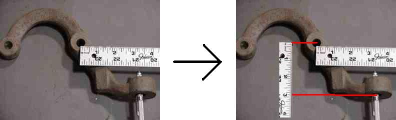
I already have those tapered studs, and also got a tapered reamer so that I can use nice Moog tie rods for the relocated upper holes. Plan is (pending what some linkage sketching and kinematics reveals) to move inner tie rods up the 2", and the outer tie rod up the difference between my current steering arms and the new, no-drop A-body ones, which now looks to be about 3". I'll take advantage of this lob-sided height raise on the outboard end to have some up/down wiggle room with those tapered steering studs. The steering arms will also most likely be moved inboard from the wheel about 1/2" due to likely interference with the Wilwood caliper. Due to this, again pending computer stuff, if the bumpsteer is better or worse with the shortened tie rod assembly, then the inner tie rod location will be adjusted up/down/inboard/outboard on the draglink to optimize.
11-19-2012, 02:35 PM
#1091
joe, are you CADing any of this up at all, aside from some of the stuff you designed for your swap? I think it would be pretty awesome to design a model of the car to essentially test potential chassis/suspension changes beforehand. sadly, I'm not in the design side of things, so I have to rely on others to translate my designs onscreen (since they can accomplish in less than an hour what takes me a day).
edit: clint, don't forget he's in america's tuke, so shipping over the border will probably be expensive.
edit: clint, don't forget he's in america's tuke, so shipping over the border will probably be expensive.

I have been heavily throwing around the idea of 3D modelling a lot of this crap I've made, but after asking around a bunch on Lat-G and Pro-Tour, I could never get even a simplified LS engine model, so that kindof killed it. If I had got an LS 3D, I bet this whole process would've taken soooo much longer. For a while I have been wanting to take comprehensive measurements of the subframe w/ suspension pickup points, and it looks like this new project will finally require it, so I can get some hard numbers for actual camber gain, caster, bump, etc, however I doubt it will make it much past the minimum point-to-point line sketches needed in ProE to get the necessary info.
11-19-2012, 02:40 PM
#1092
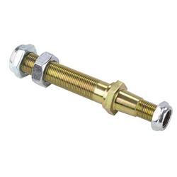
My plan for the studs is to not sandwich the heim with a nut above/below.. this is unsafe and just scares me. What I plan on doing is drilling the stud to accept a cotter pin at a finite distance down the stud, and sandwich the heim to the stud with a finite overall spacer thickness. This way, if it needs adjustment up/down, I can re-arrange the spacers above/below the heim joint and maintain the same overall spacer stack height, with it all tightened by a castlenut w/ cotter pin for piece of mind.
11-19-2012, 03:30 PM
#1093
Teching In

Join Date: May 2012
Location: Pampa, Texas
Posts: 48
Likes: 0
Received 0 Likes
on
0 Posts
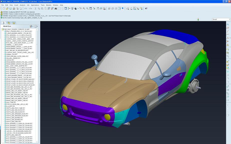
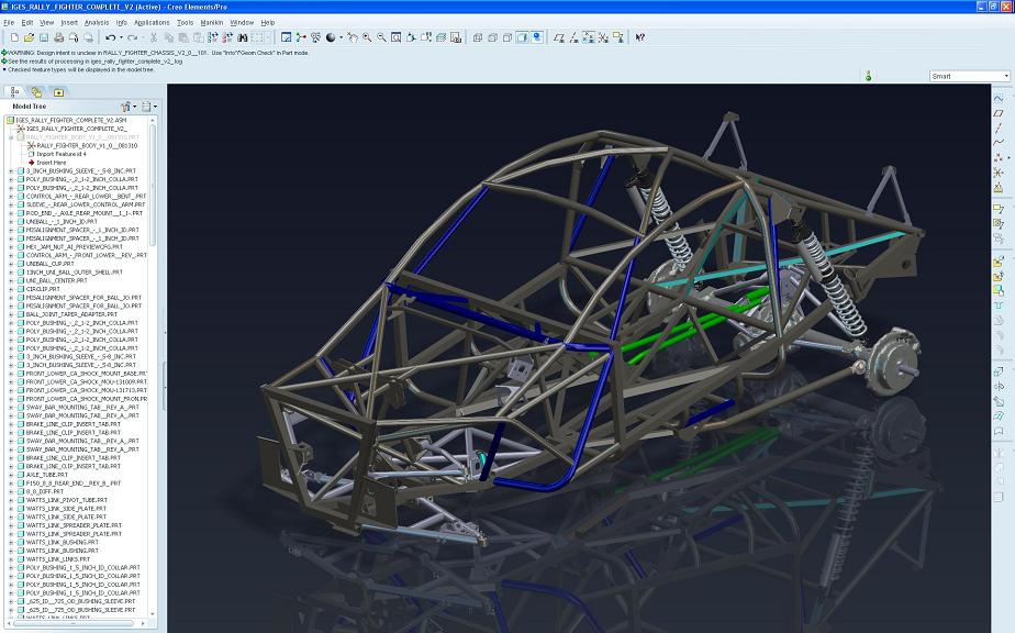
as for a 3d model of an ls motor this is the best one i've ever seen and it's free... i used solidworks daily and i downloaded the "Complete" model and then i can just pick and choose what i want to use...
http://rallyfighter.com/downloads/
here's a pic of what it looks like...
http://rallyfighter.com/downloads/
here's a pic of what it looks like...
Last edited by 68wagon; 11-19-2012 at 03:46 PM.
11-19-2012, 04:20 PM
#1095
Teching In
Join Date: May 2012
Location: Pampa, Texas
Posts: 48
Likes: 0
Received 0 Likes
on
0 Posts
Yea and if you get the whole model then it also has a 4l80.... i've used it already a few times to do some figuring on my ls swap.... the only kicker with this model and using it for me is i'm running a ls1 and this is a 6.2 ls3 i believe....
 11-19-2012, 04:38 PM
#1097
Teching In
Join Date: May 2012
Location: Pampa, Texas
Posts: 48
Likes: 0
Received 0 Likes
on
0 Posts
Sure, but the IGES file is 67mb.... lol... i doubt that will go over email... i can try my dropbox.... send me your address and i'll see what we can workout...
Last edited by 68wagon; 11-19-2012 at 04:43 PM.