New STS F-body Turbo System!!!
 04-21-2009, 09:11 AM
#1
TECH Regular
Thread Starter
Join Date: Nov 2006
Posts: 465
Likes: 0
Received 0 Likes
on
0 Posts

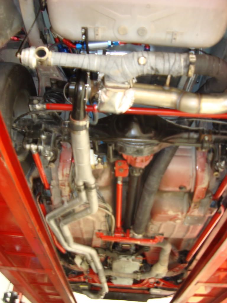
Here are a few pictures of the new and improved f-body turbo system from STS. Go to the website at www.ststurbo.com for options and pricing.
This is the new air intake that tucks the filter up next to the fuel filler neck.
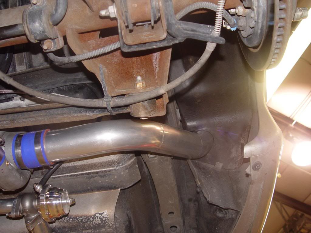
Just lightly trim the factory plastic and the filter is completly out of all the elements.
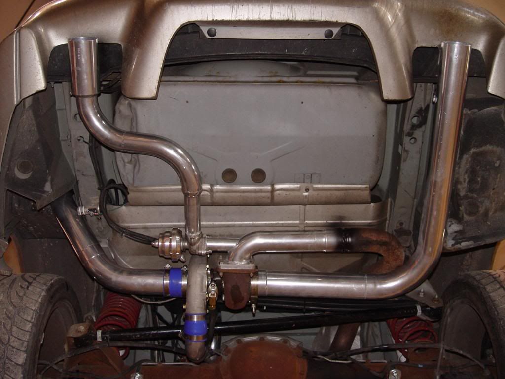
Here is the new exhaust assembly which now has 2 tips to retain the dual exaust look.
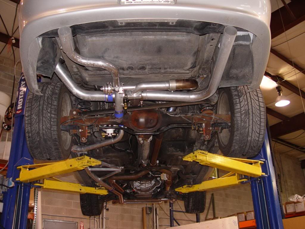
This new assembly has a hanger for each tip and all of the intake pipes have their own mounts for a much more solid and long lasting system.
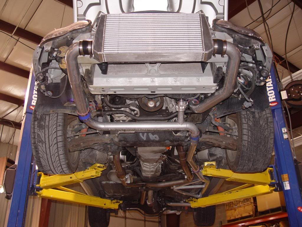
Here is the new front mount intercooler kit which is a direct bolt on. No need to remove or cut up the front bumper.
Feel free to ask any questions or request any pictures of specific parts of the system.
This is the new air intake that tucks the filter up next to the fuel filler neck.
Just lightly trim the factory plastic and the filter is completly out of all the elements.
Here is the new exhaust assembly which now has 2 tips to retain the dual exaust look.
This new assembly has a hanger for each tip and all of the intake pipes have their own mounts for a much more solid and long lasting system.
Here is the new front mount intercooler kit which is a direct bolt on. No need to remove or cut up the front bumper.
Feel free to ask any questions or request any pictures of specific parts of the system.
Last edited by Turbo 6.0; 04-24-2009 at 01:09 AM.

 04-21-2009, 09:41 AM
#3
TECH Enthusiast
iTrader: (16)
Join Date: Jun 2004
Location: Farmingville, New York
Posts: 586
Likes: 0
Received 0 Likes
on
0 Posts
Are the new pieces available as a retrofit? I have an old system (used) I have yet to install and would be interested in the new intake pipe and exhaust pipes in particular. Thanks!

 04-21-2009, 06:23 PM
#5
TECH Regular
Thread Starter
Join Date: Nov 2006
Posts: 465
Likes: 0
Received 0 Likes
on
0 Posts
Our only retro-fit kit that we have is the intercooler but I'm we could send you all the parts needed to use the new style exhaust and air intake pipe with the intake pipes you currently have.
04-21-2009, 07:59 PM
#7
TECH Resident
iTrader: (17)
Join Date: Sep 2004
Location: NC - Charlotte area
Posts: 3,747
Likes: 0
Received 0 Likes
on
0 Posts
NICE!!! I have heard about the changes from several people!! I like it.
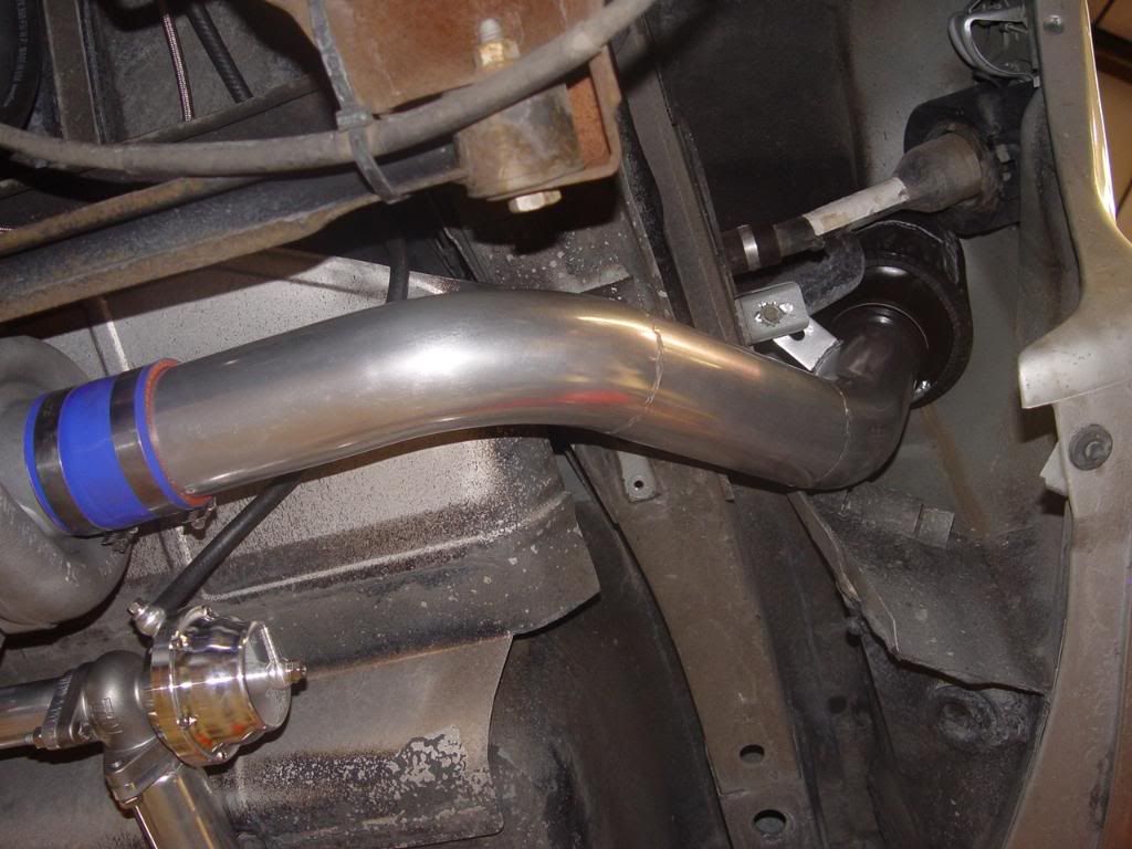
I still wish they would use a "tube/hose" to go under the axle....I'm doing it on mine and its awesome. It even looks like the routed that pipe better and gained some ground clearance. However, it looks like they straightened out a LOT of pipes and ran everything a LOT better than it was.
I gotta give credit where its due.
Trending Topics
04-21-2009, 08:10 PM
#8
TECH Enthusiast
iTrader: (9)
Join Date: Oct 2005
Location: Greenville, Raleigh NC
Posts: 702
Likes: 0
Received 0 Likes
on
0 Posts
I like the looks of the new kit, and an intercooler was much needed! I agree about the under the axle pipes. But I wonder how much air is up in that finder and if that becomes a restriction when up in the boost.
04-22-2009, 09:26 AM
#10
TECH Regular
Thread Starter
Join Date: Nov 2006
Posts: 465
Likes: 0
Received 0 Likes
on
0 Posts
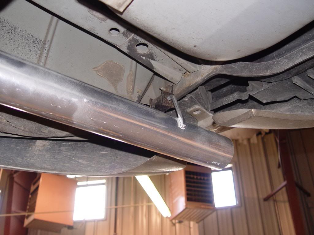
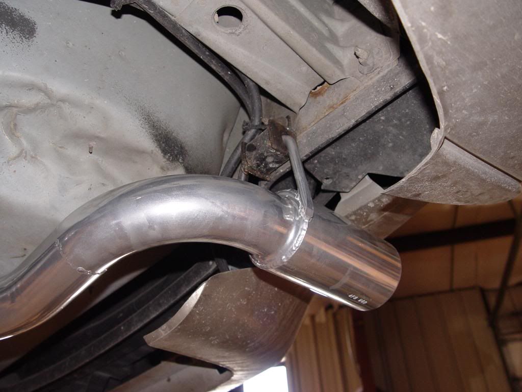
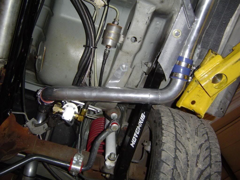
Here are a few pics of the hangers on the both the tail pipe and the wastgate dump pipe. They simply bolt onto factory studs and add a lot more stability to the entire exhaust system.
 04-22-2009, 09:27 AM
#11
TECH Regular
Thread Starter
Join Date: Nov 2006
Posts: 465
Likes: 0
Received 0 Likes
on
0 Posts
NICE!!! I have heard about the changes from several people!! I like it.
I still wish they would use a "tube/hose" to go under the axle....I'm doing it on mine and its awesome. It even looks like the routed that pipe better and gained some ground clearance. However, it looks like they straightened out a LOT of pipes and ran everything a LOT better than it was.
I gotta give credit where its due.
04-22-2009, 09:32 AM
#12
TECH Regular
Thread Starter
Join Date: Nov 2006
Posts: 465
Likes: 0
Received 0 Likes
on
0 Posts
That is a good point. We found that when making more than 8psi the snorkle pipe does cause a bit a a restriction but it is perfect for dailey drivers. We also offer a 4" "high flow" pipe that is simular to the old system but is made of 4" pipe and has a much stronger mounting bracket. It is also a fairly easy pipe to change so you can use the 4" pipe at the track then reinstall the snorkle pipe to drive home.
 04-23-2009, 12:41 PM
#14
Super Slow SS wrote:
...I wonder how much air is up in that fender and if that becomes a restriction when up in the boost.
Then Turbo 6.0 wrote:
That is a good point.
We found that when making more than 8psi the snorkle pipe does cause a bit a a restriction but it is perfect for dailey drivers. We also offer a 4" "high flow" pipe that is simular to the old system but is made of 4" pipe and has a much stronger mounting bracket. It is also a fairly easy pipe to change so you can use the 4" pipe at the track then reinstall the snorkle pipe to drive home.
My $0.02 -
I know the idea of the air filter location is to completely remove it from rain, ice, dirt, and snow - so the placement is correct. To resolve the low pressure issue, simple place a few (i.e. - 3 or 4) 1/2 dia holes in the plastic shield to allow air in. It will slightly compromise the protection of the shield, but this will resolve the air starvation issue completely.
MIKE

 04-23-2009, 01:17 PM
#17
Super Slow SS wrote:
...I wonder how much air is up in that fender and if that becomes a restriction when up in the boost.
Then Turbo 6.0 wrote:
That is a good point.
We found that when making more than 8psi the snorkle pipe does cause a bit a a restriction but it is perfect for dailey drivers. We also offer a 4" "high flow" pipe that is simular to the old system but is made of 4" pipe and has a much stronger mounting bracket. It is also a fairly easy pipe to change so you can use the 4" pipe at the track then reinstall the snorkle pipe to drive home.
My $0.02 -
I know the idea of the air filter location is to completely remove it from rain, ice, dirt, and snow - so the placement is correct. To resolve the low pressure issue, simple place a few (i.e. - 3 or 4) 1/2 dia holes in the plastic shield to allow air in. It will slightly compromise the protection of the shield, but this will resolve the air starvation issue completely.
MIKE
...I wonder how much air is up in that fender and if that becomes a restriction when up in the boost.
Then Turbo 6.0 wrote:
That is a good point.
We found that when making more than 8psi the snorkle pipe does cause a bit a a restriction but it is perfect for dailey drivers. We also offer a 4" "high flow" pipe that is simular to the old system but is made of 4" pipe and has a much stronger mounting bracket. It is also a fairly easy pipe to change so you can use the 4" pipe at the track then reinstall the snorkle pipe to drive home.
My $0.02 -
I know the idea of the air filter location is to completely remove it from rain, ice, dirt, and snow - so the placement is correct. To resolve the low pressure issue, simple place a few (i.e. - 3 or 4) 1/2 dia holes in the plastic shield to allow air in. It will slightly compromise the protection of the shield, but this will resolve the air starvation issue completely.
MIKE
Agreed. I did this with my intake setup on my 95 and it helped. Noticed a little better throttle response and gas mileage on the freeway.
 04-23-2009, 02:53 PM
#19
TECH Enthusiast
iTrader: (8)
Join Date: Apr 2008
Location: Tampa/Valrico, FL/ Chicago, IL
Posts: 555
Likes: 0
Received 0 Likes
on
0 Posts
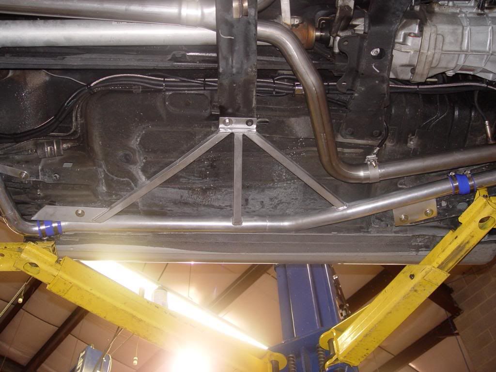
dont mean to hijack the thread but a good point was brought up can you run subframes on a rear mount car and if so anyone have pics of their fab work to make it work.. thanks
04-23-2009, 05:08 PM
#20
9 Second Club
iTrader: (2)
Join Date: Jun 2005
Location: Reston, VA
Posts: 2,034
Likes: 0
Received 0 Likes
on
0 Posts
Here is a bad pic under mine... but you can see the red BMR subframe rail on each side...