Fuel Upgrade Install (pic heavy)
 09-05-2016, 08:27 PM
#1

So after gathering all the parts I needed for my return-setup fuel upgrades I decided to take this extended weekend to install everything
parts list:
Aeromotive Stealth 340 Center inlet fuel pump
Brand New Delphi fuel pump module
Racetronix hotwire kit
Magnafuel MP-9925 FPR
Billet fuel rails (previously installed)
Various AN fittings and hoses
I did this install by dropping the tank as opposed to cutting a trap door for 2 reasons.. 1. I am not too keen on cutting metal right above the fuel tank (still has 1/4 of gas) and 2. I didnt want to cut a giant hole in the car.. I was also blessed by having a dumped exhaust so I didnt have to fool with that as well.
first things first is to DISCONNECT THE NEGATIVE BATTERY CABLE! and then jack up the car and remove the panhard brace and panhard itself
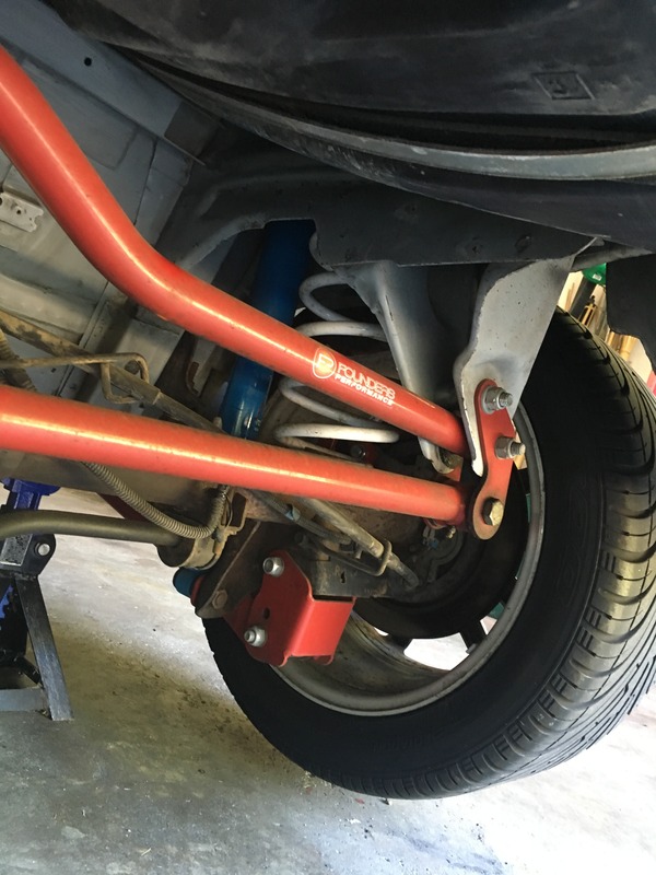
(btw, thats PB blaster on the fuel tank)
next is to take off the plastic shield below the filler neck and the two exhaust heat shields (1 push fastener and 1 7mm bolt and seven 7mm bolts for heat shields)
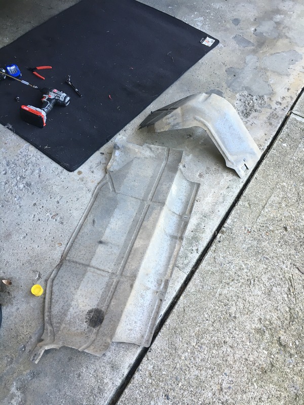
that allows access to the 10mm bolt that holds the fuel filler to the car
Also take out the 2 phillips screws and pull out the filler neck ring by the gas door.
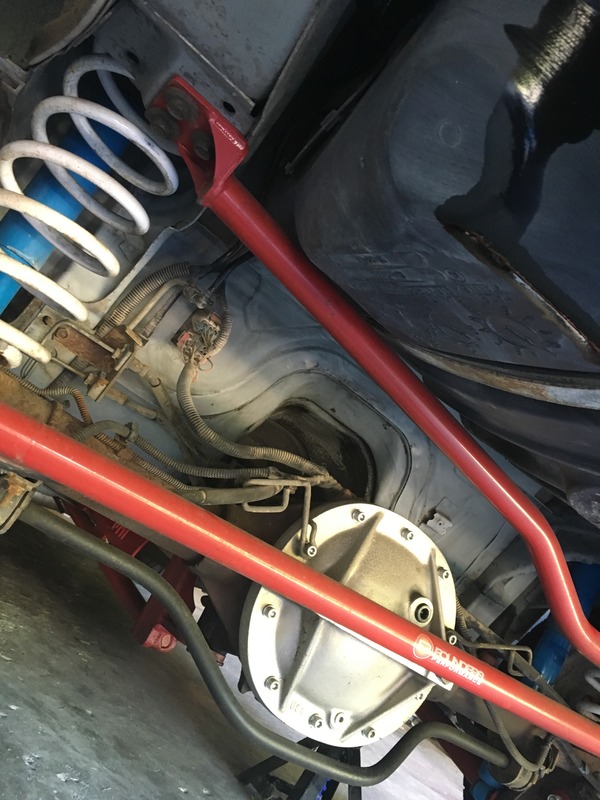
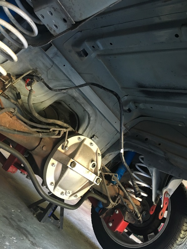
I forgot to take pics of this part but now you can remove the 2 13mm bolts holding the fuel tank straps up and swing them down out of the way (after clearing the rear end stuff) remove the return and evap fittings (push in to release
then pull the tank down and release the feed hose fitting from the module and then out with the built in ring handles on the sides
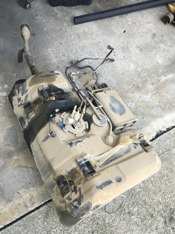
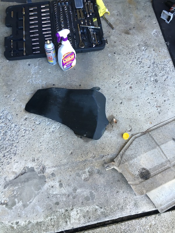
pretty filthy (I used purple power to clean it up)
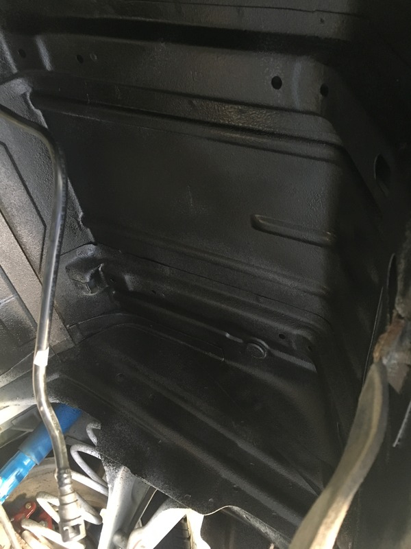
surprisingly the underneath was pretty clean
perfect opportunity to spray the area with some Boom Mat sound deadening spray
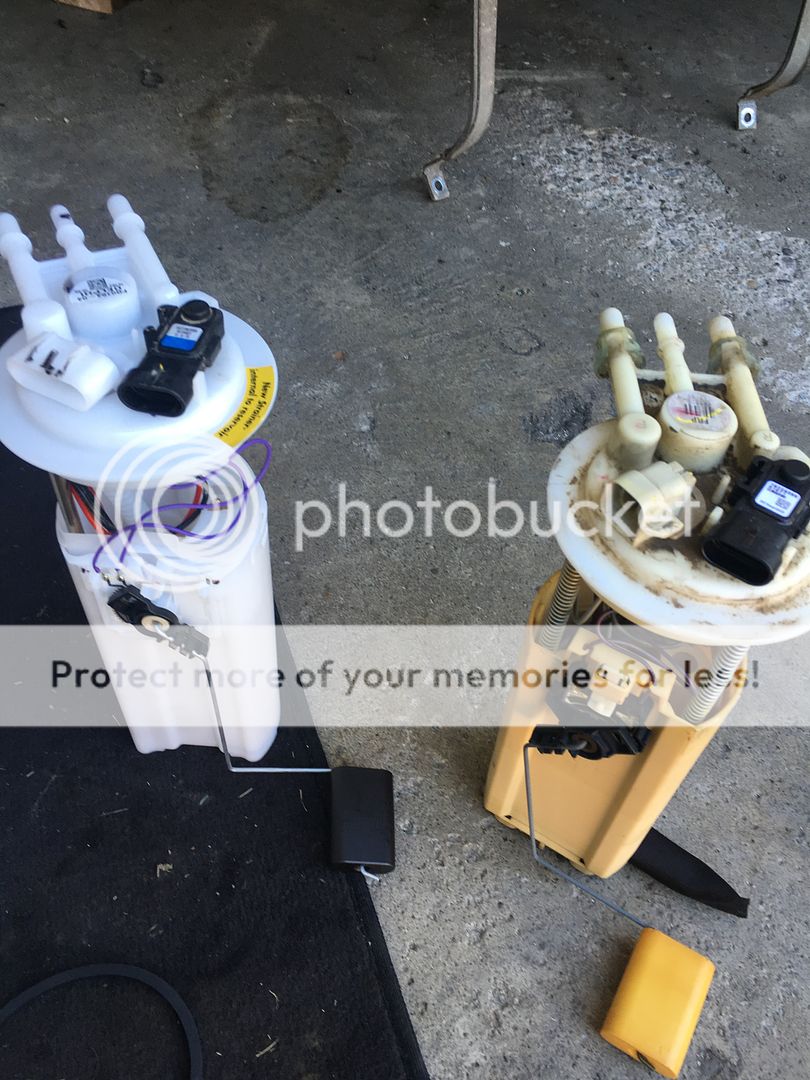
Old module and new Module with Aeromotive 340 already installed
parts list:
Aeromotive Stealth 340 Center inlet fuel pump
Brand New Delphi fuel pump module
Racetronix hotwire kit
Magnafuel MP-9925 FPR
Billet fuel rails (previously installed)
Various AN fittings and hoses
I did this install by dropping the tank as opposed to cutting a trap door for 2 reasons.. 1. I am not too keen on cutting metal right above the fuel tank (still has 1/4 of gas) and 2. I didnt want to cut a giant hole in the car.. I was also blessed by having a dumped exhaust so I didnt have to fool with that as well.
first things first is to DISCONNECT THE NEGATIVE BATTERY CABLE! and then jack up the car and remove the panhard brace and panhard itself
(btw, thats PB blaster on the fuel tank)
next is to take off the plastic shield below the filler neck and the two exhaust heat shields (1 push fastener and 1 7mm bolt and seven 7mm bolts for heat shields)
that allows access to the 10mm bolt that holds the fuel filler to the car
Also take out the 2 phillips screws and pull out the filler neck ring by the gas door.
I forgot to take pics of this part but now you can remove the 2 13mm bolts holding the fuel tank straps up and swing them down out of the way (after clearing the rear end stuff) remove the return and evap fittings (push in to release
then pull the tank down and release the feed hose fitting from the module and then out with the built in ring handles on the sides
pretty filthy (I used purple power to clean it up)
surprisingly the underneath was pretty clean
perfect opportunity to spray the area with some Boom Mat sound deadening spray
Old module and new Module with Aeromotive 340 already installed
 09-05-2016, 08:48 PM
#2
Before I slapped the tank back up which was a PITA with me myself and I doing it with a jack.. I connected the Racetronix harness to the new module and the old wiring and ziptied it along the old wiring route on the top of the tank (no pics sorry)
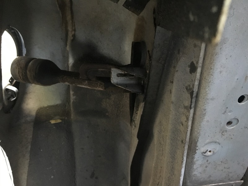
If you are going to a return setup you need to remove this fuel line and use a 1/4" NPT plug on the T-fitting
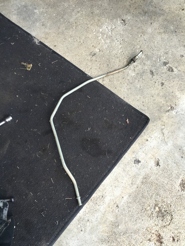
that line comes out of the T-fitting by the fuel filter and the other end was connected to the return hose from the module.. the return hose on the module now will connect to the evap line that runs to the engine bay.
Relay is mounted here
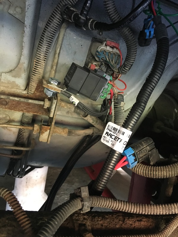
the EVAP hose from the pump module runs through the charcoal box and valve on top of the tank before connecting to the car.. that gets left unhooked and I found a filter to attach to the end of it.
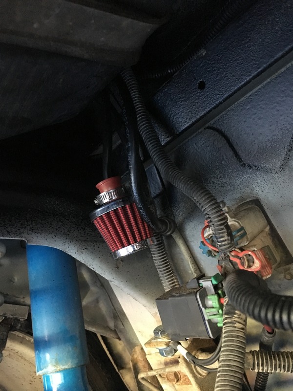
Run the racetronix harness along the frame of the car (I ziptied it to the fuel lines running up the car) and attach the end to the Alternator post.
Engine bay before
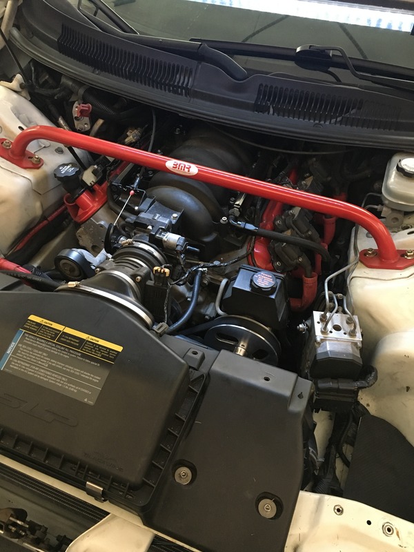
already have billet rails and a -8 feed connected to the supply line and the crossover at the back
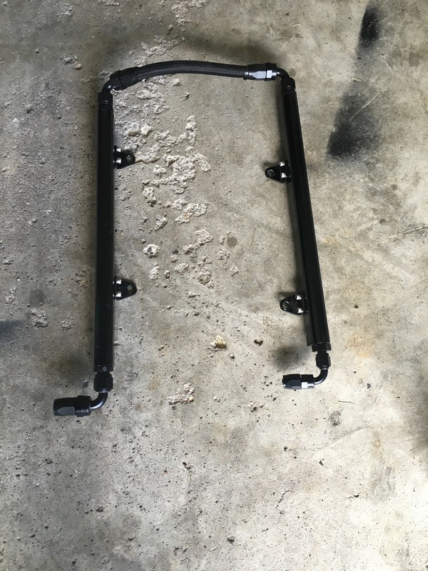
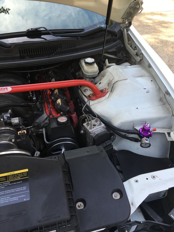
crossover is now at the front and a -8 feed on drivers side rail and a -6 return on passenger side rail
return and feed are routed around from the back
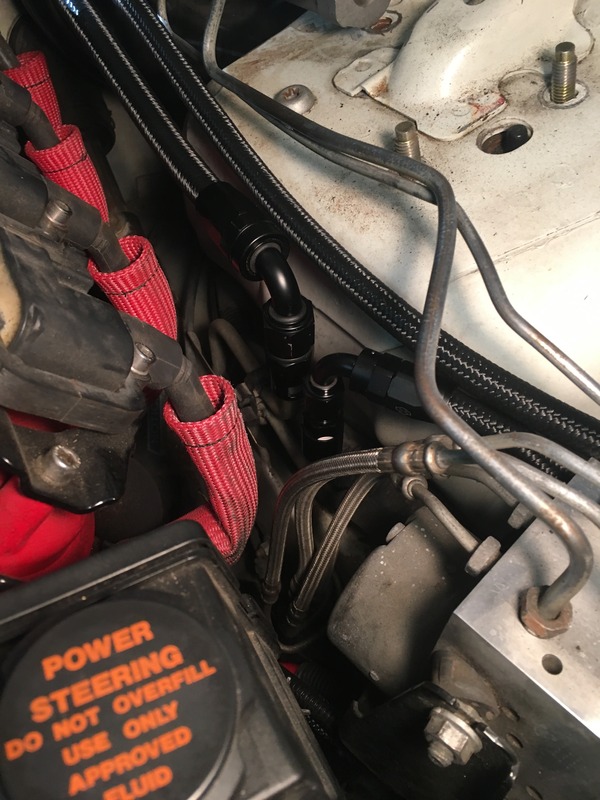
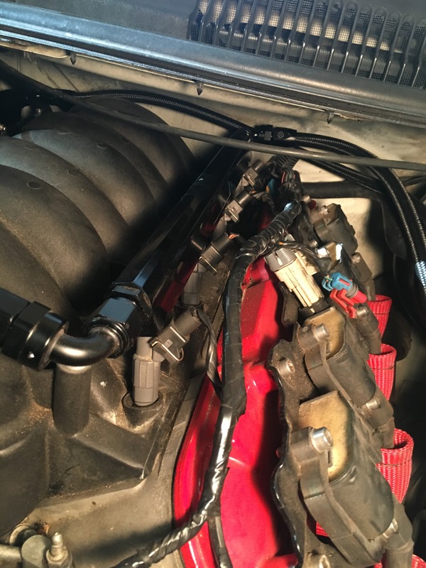
feed goes to -8 90 fitting to the supply line and the -6 feed routes around to the FPR
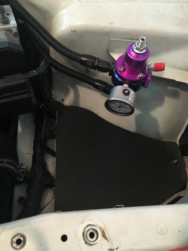
-6 return comes out the bottom of the FPR with a -6 90 fitting back to the now return line with another -6 90 fitting (see above pic)
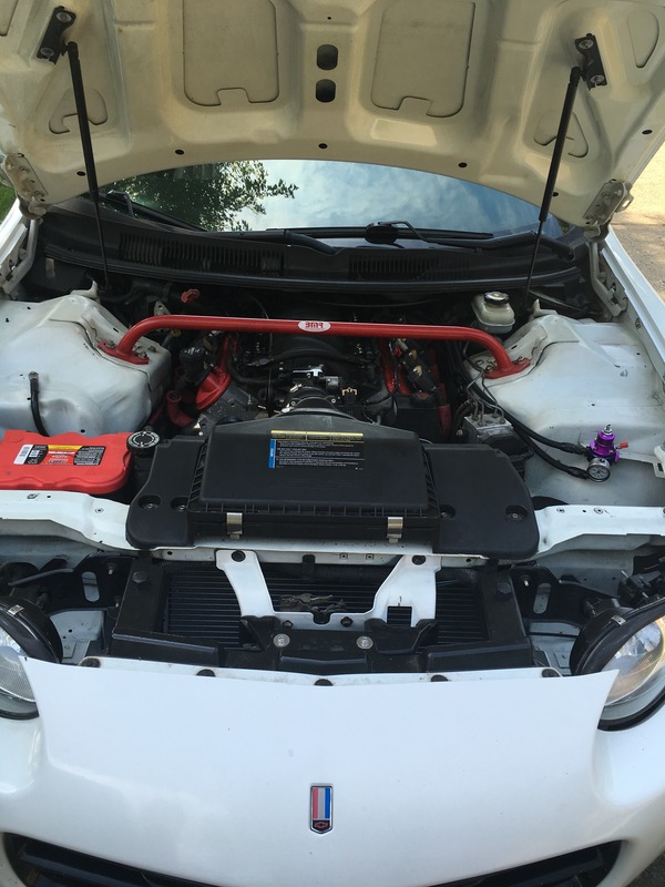
here is what it looks like done
I ordered billet hose clamps for the lines and I need to hook up the boost reference fitting to a vacuum source but it runs and drives fine..
I'll update this thread when I do those things..
also need to mount my fuel pressure gauge so it faces up for easier readings
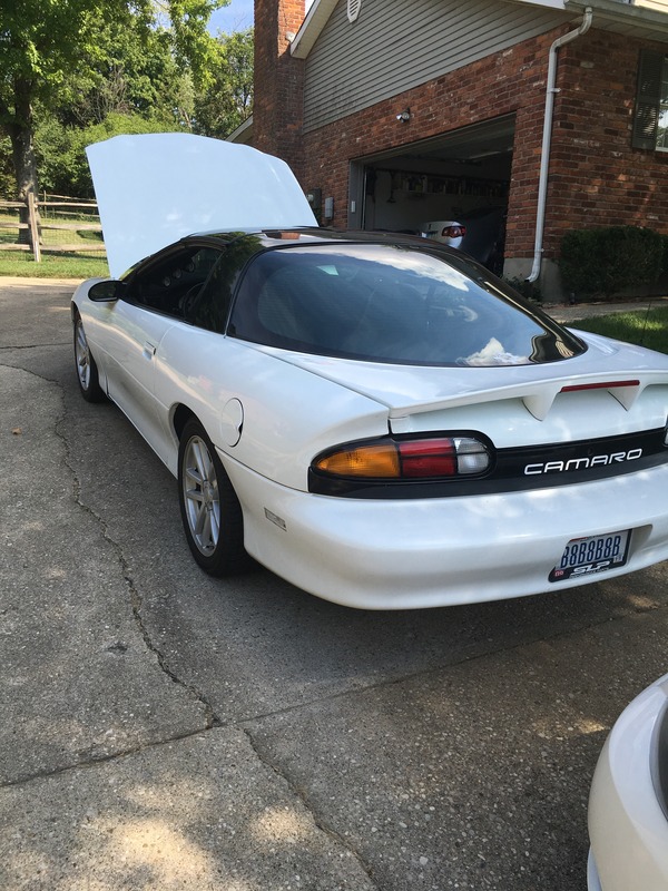
and a beauty shot
If you are going to a return setup you need to remove this fuel line and use a 1/4" NPT plug on the T-fitting
that line comes out of the T-fitting by the fuel filter and the other end was connected to the return hose from the module.. the return hose on the module now will connect to the evap line that runs to the engine bay.
Relay is mounted here
the EVAP hose from the pump module runs through the charcoal box and valve on top of the tank before connecting to the car.. that gets left unhooked and I found a filter to attach to the end of it.
Run the racetronix harness along the frame of the car (I ziptied it to the fuel lines running up the car) and attach the end to the Alternator post.
Engine bay before
already have billet rails and a -8 feed connected to the supply line and the crossover at the back
crossover is now at the front and a -8 feed on drivers side rail and a -6 return on passenger side rail
return and feed are routed around from the back
feed goes to -8 90 fitting to the supply line and the -6 feed routes around to the FPR
-6 return comes out the bottom of the FPR with a -6 90 fitting back to the now return line with another -6 90 fitting (see above pic)
here is what it looks like done
I ordered billet hose clamps for the lines and I need to hook up the boost reference fitting to a vacuum source but it runs and drives fine..
I'll update this thread when I do those things..
also need to mount my fuel pressure gauge so it faces up for easier readings
and a beauty shot
Last edited by Majestic9C1; 09-05-2016 at 08:53 PM.