BMR Subframe Connector Installation How-to
 01-14-2011, 10:54 AM
#1

I was thinking about this the other day and realized that a lot of people may be intimidated by the complexity of this installation when, in fact, it is probably one of the easiest and quickest mods you can do to your new Camaro. Once the vehicle is in the supported, the whole process can be done in as little as an hour!
If interested, follow along as we show you how simple it is to install our SFC015[/URL] subframe connectors on your 2010+ Camaro.
NOTE: It is recommended to perform this installation with the suspension loaded. It is possible to use drive-on ramps as long as the full weight of the vehicle is resting on the wheels/tires and the suspension is fully loaded.
Required Tools:
� 3/8� ratchet
� 15mm socket
� 3/8� Allen wrench or Allen socket
Installation Procedure:
1. Lift vehicle.
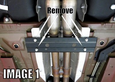
2. Using a 15mm socket, remove the four bolts that secure the OE driveshaft tunnel brace and remove the brace. (see IMAGE 1)
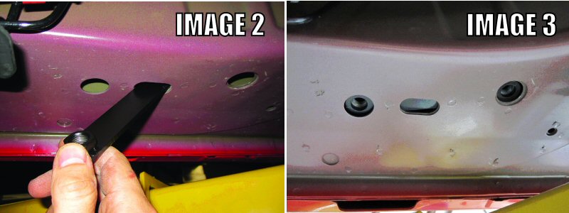
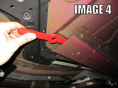
3. Locate the 2 sets of frame inserts provided with your BMR Subframe Connectors. The smaller of the two fits the rear frame rails and the larger fits the front rails. As shown in Image 2 below, slide the smaller insert up through the oblong frame hole and into the frame rail. It should fall rearward, then can be positioned over the existing holes as in Image 3.
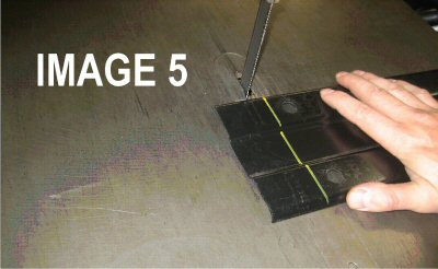
4. Slide the larger front frame inserts into the front rails and position them over the existing frame holes as in Image 4 below.
5. Choose a side and hold a subframe connector up into place as shown in the last image on the following page. Insert (2) of the supplied �� Allen bolts and washers into the rear-most bolt holes and (1) into the most forward bolt-hole. Thread the 10mm bolts into the remaining holes. Do not tighten any of the bolts until all six bolts are partially threaded in. NOTE: a screwdriver or tapered alignment tool may be used to line up the bolt holes.
6. Once all bolts are inserted, tighten the �� Allen bolts to 45 ft/lbs.
7. Remove the (2) 10mm tunnel brace bolts that were installed in step 5 above.
8. Repeat steps 5-6 for the other subframe connector.
9. If re-using the factory tunnel brace, it is necessary to modify the brace for re-installation. Begin by measuring 2� from each end and marking the tunnel brace for cutting. As shown in Image 5, cut along the previous mark using a bandsaw, hacksaw, or cut-off wheel. Re-install tunnel brace over the subframe connectors and thread the 10mm bolts back into place. Tighten bolts to 48 ft/lbs. NOTE: BMR heavy duty tunnel brace shown below is highly recommended to take full advantage of the subframe connectors. When using this brace, no modifications are necessary.
10. Lower vehicle.

If interested, follow along as we show you how simple it is to install our SFC015[/URL] subframe connectors on your 2010+ Camaro.
NOTE: It is recommended to perform this installation with the suspension loaded. It is possible to use drive-on ramps as long as the full weight of the vehicle is resting on the wheels/tires and the suspension is fully loaded.
Required Tools:
� 3/8� ratchet
� 15mm socket
� 3/8� Allen wrench or Allen socket
Installation Procedure:
1. Lift vehicle.
2. Using a 15mm socket, remove the four bolts that secure the OE driveshaft tunnel brace and remove the brace. (see IMAGE 1)
3. Locate the 2 sets of frame inserts provided with your BMR Subframe Connectors. The smaller of the two fits the rear frame rails and the larger fits the front rails. As shown in Image 2 below, slide the smaller insert up through the oblong frame hole and into the frame rail. It should fall rearward, then can be positioned over the existing holes as in Image 3.
4. Slide the larger front frame inserts into the front rails and position them over the existing frame holes as in Image 4 below.
5. Choose a side and hold a subframe connector up into place as shown in the last image on the following page. Insert (2) of the supplied �� Allen bolts and washers into the rear-most bolt holes and (1) into the most forward bolt-hole. Thread the 10mm bolts into the remaining holes. Do not tighten any of the bolts until all six bolts are partially threaded in. NOTE: a screwdriver or tapered alignment tool may be used to line up the bolt holes.
6. Once all bolts are inserted, tighten the �� Allen bolts to 45 ft/lbs.
7. Remove the (2) 10mm tunnel brace bolts that were installed in step 5 above.
8. Repeat steps 5-6 for the other subframe connector.
9. If re-using the factory tunnel brace, it is necessary to modify the brace for re-installation. Begin by measuring 2� from each end and marking the tunnel brace for cutting. As shown in Image 5, cut along the previous mark using a bandsaw, hacksaw, or cut-off wheel. Re-install tunnel brace over the subframe connectors and thread the 10mm bolts back into place. Tighten bolts to 48 ft/lbs. NOTE: BMR heavy duty tunnel brace shown below is highly recommended to take full advantage of the subframe connectors. When using this brace, no modifications are necessary.
10. Lower vehicle.