
TAURUS FAN WIRING HELP! Diagram Inside
 02-12-2012, 04:09 PM
#1
Teching In
Thread Starter
iTrader: (11)

Join Date: Sep 2007
Location: San Diego
Posts: 21
Likes: 0
Received 0 Likes
on
0 Posts
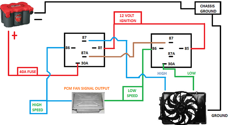
Hey guys, I'm trying to hook up my Taurus fan setup and made a diagram of how I am going to wire it up. Now I have very little electrical skills  and would like you guys to critique this setup and tell me where I've gone wrong.
I will be utilizing (2) OEM Taurus Relay's and a 40 Amp Fuse in line. Here's a diagram of my plan.
I really would appreciate the help guys!
and would like you guys to critique this setup and tell me where I've gone wrong.I will be utilizing (2) OEM Taurus Relay's and a 40 Amp Fuse in line. Here's a diagram of my plan.
I really would appreciate the help guys!
 02-13-2012, 09:54 AM
#2

So, 85 and 86 are the coil? 30 to 87a are NC and 30 to 87 are NO? Where's the gound for the relays(coils)? You show 85's connected to 12v ign source and 86's connected to PCM out. I don't know how that part works but if the PCM switches to ground then it would work as long as the 12v ign was switched on? When I say work I mean you will have power at either the blue or green wire only, depending on the PCM. So if you have dual fans and "high" is the second fan coming on then no that will not work.
Someone correct me if I'm wrong, but that's what it looks like to me. LOL
Someone correct me if I'm wrong, but that's what it looks like to me. LOL