
2000 LS1 Corvette Accelerator Pedal Pin out
 06-07-2012, 08:40 PM
#1

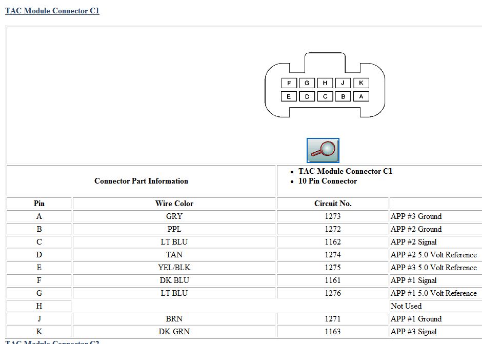
Can anyone show me the connector end view/pin out of the Accelerator pedal (both ends of the harness) and the TAC Module connector end from the engine harness for a 2000 LS1 Corvette? I need to make up a harness from my pedal to the TAC module and I need to wire the extra leads of the engine harness connector that goes to the TAC module. Thanks in advance.
 06-08-2012, 05:39 PM
#2
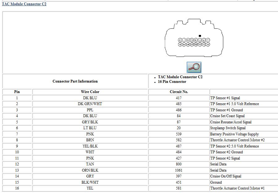
Figured out all but 1 wire for the 16 pin TAC Module connector. It's a Light Blue wire in terminal 6. Does anyone know what this wire is for? I have to make a Accelerator Pedal harness and on the pedal there are only 9 terminals used out of the 10 terminal connector end. Do I run the wires for the new connector ends, A to A, B to B, and so on? Or are any of them not directly correlated with the other end?
My cousin bought a pedal harness made for his engine that he doesn't have plans to install yet and on his harness the wires don't directly correlate with the other end because 2 of the 9 wires are swapped. Is his wrong? A wiring diagram would be helpful here but I can not find one.
My cousin bought a pedal harness made for his engine that he doesn't have plans to install yet and on his harness the wires don't directly correlate with the other end because 2 of the 9 wires are swapped. Is his wrong? A wiring diagram would be helpful here but I can not find one.
 06-09-2012, 10:34 PM
#4
Thank you very much. So is the blue wire to be hooked up to the brake switch for cruise control only? I plan on installing a cruise switch so I will need it. Also you do know if the C1 connector for the pedal to TAC module is the same on each connector end since it uses the same connector style?


