When you click on links to various merchants on this site and make a purchase, this can result in this site earning a commission. Affiliate programs and affiliations include, but are not limited to, the eBay Partner Network.
I wanted to share my experience with installing a FAST 102 setup for my car, because I spent way too much time trying to find all the right info before purchasing. Even then, I didn't really get complete information until I went through the install process. And unfortunately, my setup might be changing a little, which I'll explain shortly. Let's start with some part numbers.
And some more...
-FAST Billet Rails for LS1 Part# 146032-KIT
-FTP 104 Lid
-Spectre 9705 housing
-ACDelco 213-4222 GM Original Equipment Mass Air Flow Sensor with Intake Air Temperature Sensor
-LS7 to LS1 wiring harness **This becomes a problem for me**
-2x Spectre 4" silicone couplers
-Various clamps at the tube connections
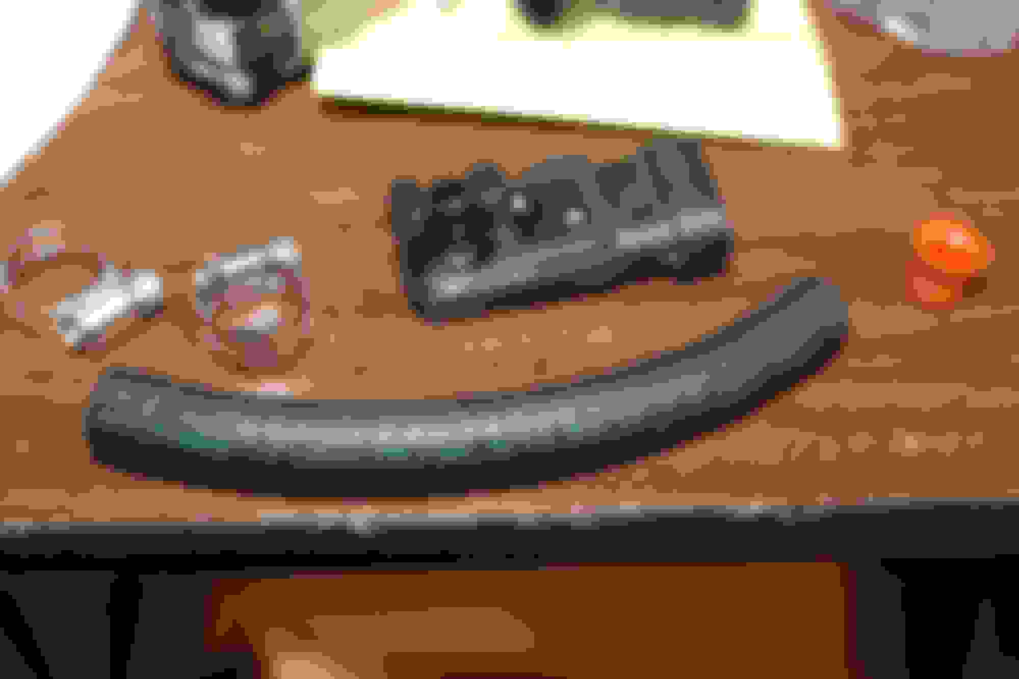
OK, so let's put this thing together. I chose the rear MAP location and also chose to relocate it upwards. Follow the directions given by FAST to drill the hole. Here's what I used:
5/16" fuel hose and 2 small clamps. Removed rubber grommet from MAP.
Brass 90* fitting sealed in the port with blue RTV sealant.
Here it is assembled.
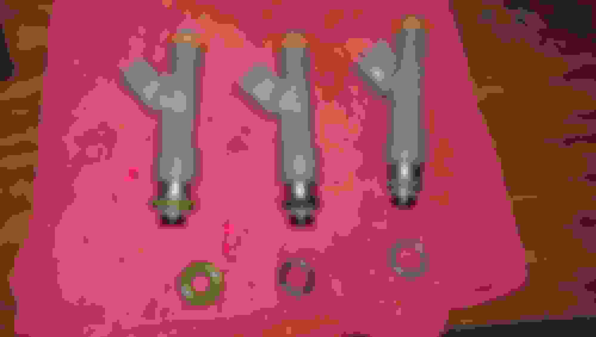
That was easy. The first annoying part was trying to get the injectors and o-rings to seat in their holes. My kit came with 2 different o-rings, plus the injectors have their own size o-ring. The only ones that worked for MY injectors were these black ones in the middle:
Green are from FAST and don't allow the injector or o-ring to seat in the hole. Black in the middle also came from FAST and do work, but weren't as tight as I expected. Gray on the right came with the injectors and are too skinny.
A lot of discussion is had because of the mounting brackets/rails/injector height, etc etc. So for my setup with these injectors, the FAST L-shaped brackets worked just fine. It's all snug and I have no fuel leaks!
Now the fuel rail fittings on each end. I don't even know what size Allen wrench is needed, but it's bigger than anything I have or could find at Home Depot. So I remember seeing this trick somewhere to get a screw out when the head is stripped...
Keep in mind that during the install process I'm also following the FAST instructions that come with the manifold and rails. I'm not detailing every part of the process, but rather trying to point out the things that stumped me or I feel might help you along the way.
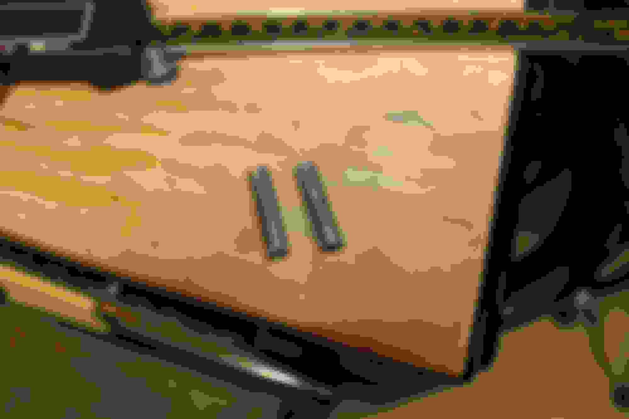
The bottom of my manifold had these metal posts (can't remember the exact name) to help locate where the manifold sits on the heads. My heads didn't have a hole for them, so they kept the manifold raised up...and scratched up the surface of my heads. I contacted FAST and they explained their purpose and that they could be removed. I had never seen or heard anyone else mention them.
The instructions say to use some rubber hose cut length-wise to slip around the 5 rear bolts that hold the manifold to the heads. That seemed annoying and wasteful with the hose so I just used some white masking tape to loosely! tape around them so they're held up out of the holes for manifold placement. You want it to come off easily since there's little room to move around back there with the injectors/rails installed and the cowl in the way. You can see my tape in the above photo of the MAP installed.
All that's left on the manifold at this point was the throttle cable bracket and sensors, then some test fitting and grinding to clear the water pump. For the cable bracket, you have these little pockets to drop some nuts in and thread the bolts from the outside. I couldn't get the nuts lined up until I grabbed one of those magnet pens to hold it in place while starting to thread the bolt. Worked like a charm.
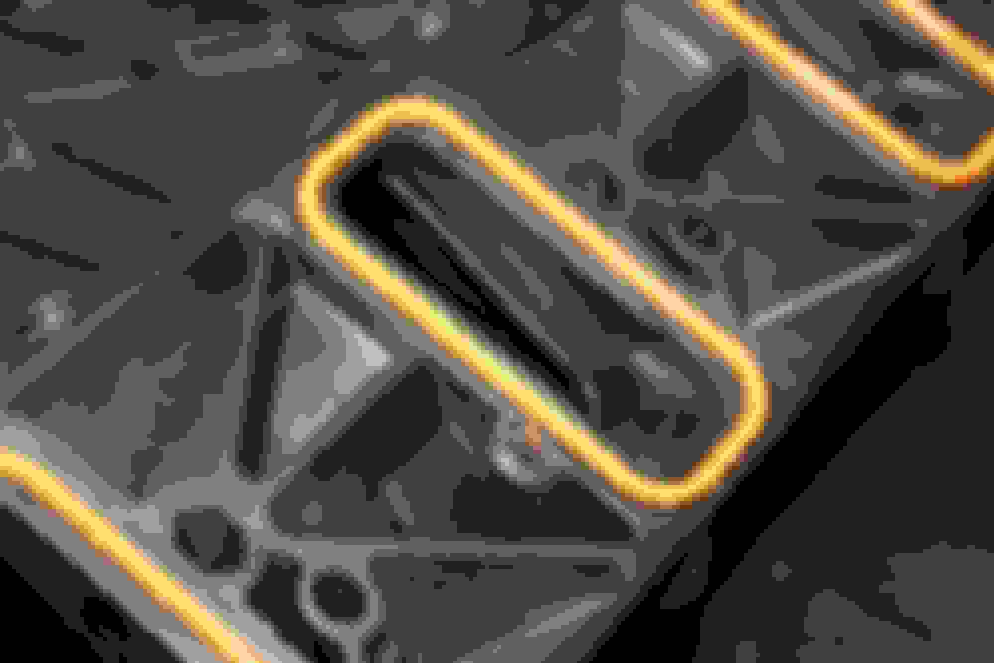
I still have the stock water pump, which required extra clearance for the manifold and TB. I wasn't touching the TB, so I chose to grind the WP and manifold. All I can tell you is do some test fitting and grinding in as many stages as it takes. Always err on the side of caution and take less than you think. Based on your heads, head gaskets, water pump, tb, etc - your requirements can and will be different. And there's no measurement I can give you, so just do little by little or get a different pump. There are threads about that and I'm not researching it for you since I don't need it
Here are some shots of grinding. I ended up having to do more than this because I forgot once I torqued down the manifold it would sit lower. So I just had to keep taking it off and putting it on, but went really quick. I didn't break my oil pressure sending unit, either. I'm not sure why everyone breaks those, but be careful.
Last edited by BREWS02WS6; 04-23-2016 at 10:15 AM.
The last part I'll go into is from the lid to the TB. For my lid to seat properly, I had to cut out about 2x2" square from the part above the radiator. Forgot what it's called, but whatever the lid and filter sit on. It just comes out with some bolts and you should see the area that's holding up the back end of the lid. My lid was also not as bad as people make them out to be. It's very stiff and at first I couldn't figure out how I could get the tabs in place without snapping it. I just started on one side and got a tab in, moved to the next one until it was all in place. My little clamp things hold the front in place just fine, too.
With me *for now* using the homemade LS7 MAF setup, I had to get some 4" silicone couplers from O'Reilly to span the gaps. These work GREAT for this setup! Nice and tight over the lid and TB, and a little less tight over the Spectre housing. I still had to use a screwdriver to get them over the housing, then finished them with clamps.
You also have to convert your 3 wire MAF sensor into the 5 wire one required on the LS7 MAF card. I got one on eBay and the wiring was wrong so my MAF was getting no reading. This continues to be an issue and is the reason my car is currently in SD mode. I want to keep the MAF and turn it back on, but I can't find the right wiring diagram so hopefully you have better luck. If I get that figured out, I'll update this thread probably and make a new one about it. If you don't want to use a MAF at all, you can get a 4x6" coupler from intakehoses.com to span the gap and lots of people recommend those. I can't confirm it for you, but others will.
I think that's about it! It really wasn't as big of a deal as others complain about. I mean, yeah it takes some extra work and thinking...but if I can do this then anyone can. Hope this helps you guys!
Last edited by BREWS02WS6; 04-23-2016 at 10:29 AM.
So what water pump is this intake designed for? I see there are some pumps that don't have that bolt in the way, can they fit F-bodys?
It's based around ls2 engines such as c6 vettes and gto's. Yes the Gto ls2 pump fits perfect. I don't think the vette one works. Also meziere electric water pumps work.
Just installed a Fast 102. Not near as bad as people have made it out to be or as bad as I thought it would be... Spend the extra money and get the Fast fuel rails. They will come with the specific brackets to mount so no spacers are needed for the injectors.
Just installed a Fast 102. Not near as bad as people have made it out to be or as bad as I thought it would be... Spend the extra money and get the Fast fuel rails. They will come with the specific brackets to mount so no spacers are needed for the injectors.
Well, this is why I made my thread.
Re: rails/injectors...not always true. Different injectors are different heights, so they require the spacers. That's why I've outlined mine so specifically, so someone who gets non-ls1 style injectors doesn't think that's all they need.
Re: rails/injectors...not always true. Different injectors are different heights, so they require the spacers. That's why I've outlined mine so specifically, so someone who gets non-ls1 style injectors doesn't think that's all they need.
I stand corrected then. Thought they made different brackets for each height injector. Thanks for making this thread.
I stand corrected then. Thought they made different brackets for each height injector. Thanks for making this thread.
They might, but they also make LS1/LS6 vs LS2 vs LS3/LS7 style FAST rails to correspond with those injectors - so they'll probably have different brackets as well. The spacer kits are to mix and match different styles. But I do agree with you that I'd rather have no spacers for this.
Sorry if I came off wrong earlier...it was early and I had zero coffee in me.

 04-23-2016, 09:54 AM