
Mod Guide: Induction and Exhaust (PLEASE READ BEFORE POSTING)

 .
.
 12-10-2005, 10:41 PM
#22
How to port your own TB
Credit: Original content and pictures were posted by Buffhomer on RacingSouthWest.com message board. http://racingsouthwest.com/forums/in...hl=porting+ls1.
Porting your the throttle body is a simple way to pickup some extra horsepower and if you already have some simple tools, it's super cheap. All you need is a dremel (or similar cutting tool) with some cutting bits, some sanding rolls, various grit sandpaper, and some quick dry metal filler of some kind (optional).
Here is a picture of the stock throttle body that we'll be working with. Our goal is to open up the area in front of the throttle blade including the front lip. You can also fill in the huge cut out area at the top (optional).

First off, you need to mark the throttle body at the blade with a marker so you be sure not to go past the blade into the backside. This is VERY IMPORTANT. If you go too far and it will not allow the throttle blade to seal and cause idle problems.
If you also plan to modify the throttle shaft (optional), you will need mark the shaft at each end where it goes into the body, like in the picture below.

Now disassemble the entire thing. Remove all the connectors, unscrew and remove the blade, and remove the shaft. After you take off the tps, you can simply whack the shaft out with a hammer. Don't feel bad it won't hurt anything. ***Pay attention as there is a very small washer that will fall out on the tps side too, do not lose this!!***

Optional: Now you need to fill in the cut out area that goes into the idle air bypass. I used 2 pieces of stainless tubing inserted before I filled it with metal filler. You can simply drill the holes later if you need to. I also put a piece of aluminum can against the opening and cut out 2 holes for the stainless tubes to slide through. This way the metal filler will not completely fill the cut out area and choke it off.

Optional: While that's drying, go ahead and knife edge the throttle blade. I used a bench grinder, but you can use the dremel if you choose. Also, round the back edge of the blade off "airflow off the back is as important as the front".

Optional: Now move over to the shaft and get ready to cut it. What you will be doing is cutting off the front portion that you see when looking at the throttle body head on. When the blade is opened up this makes a big bump and a big restriction. Reference the marks you made before you took it apart and cut there.

The shaft will look like this now:

If you used metal filler, make sure it is dry. It's now time to start porting. It will take a while, but be patient and be careful, making sure not to go too far into the throttle body (keep an eye on the mark where the blade will sit). Knife edge the leading edge of the body and grind back to your mark. Pay attention to the area near that mark, as there is a "lip" right there that is a major obstruction to air flow. You are able to feel it with your finger. Your rough cut should look something like this (if you didn't use the stainless tubes, that area will be solid filler):

Be sure not to go past your mark!!

Be careful while porting, try not to take too much material away, the casting is quite thin in areas. Be careful on the bottom due to the coolant passageways as well. All that you need to do is continue smoothing and refining the shape.
Once you're done porting it is time to begin sanding it by hand with progressively finer grit paper to smooth the finish. I went down to an 800 grit paper and finished off with a polishing wheel on the dremel. Once smoothed out you can then use a metal polishing compound to bring the metal portions of the TB to a mirror finish if desired.
If you didn't use the stainless tubes, you will now need to drill some holes for air passageways. I believe a 1/4" or 5/16" drill bit will be sufficient, just make sure you check to see that you got the holes in their proper position. Remember from the stock cut out area that there is a divider smack in the middle of that area.
Optional: You will now need to do the bump stop mod. If you didn't know, the stock bump stop for the throttle cable USUALLY won't let the blade get to true wide open throttle. It will need to be clearance to allow it to open further. There is 2 ways you can go about this.
1) with the tb installed and simply grinding till your voltage is correct or 2) with the tb off and install a set screw. I installed the setscrew to add some adjustability. Either way, you want the voltage on the tps (the blue wire) to be at 4.7V at WOT, key on/engine off. Mine ended up at 4.74V, and I can adjust it either way. I *believe* the max voltage you can have is 4.75, but I'm not 100% sure on that.

Now, reinstall the shaft into the housing. For the spring, simply set one end into the perch on the side of the housing and slide the shaft through it. Once you get the tab that it sits on up to it, put the other spring end on it and twist it all the way around till the spring is tight then push the shaft the rest of the way on. Go ahead and put the throttle blade back on the shaft and make sure it functions properly, opening and closing. Shave the backside of the screws down and it should look something like this:


Clean the assembly with a mild cleaner (I used electrical parts cleaner) and reinstall. Attach all the fittings and hose going to the valve cover, and reinstall the electronics.
Check your tps voltage to make sure it's correct. If you want, bypass the coolant that circulates through the body to keep the temps down. Simply put in a piece of tubing as a jumper between the 2 hoses and clamp them on. You don't have to worry about plugging off the fittings in the housing itself though. You can barely see it in this picture, but you get the idea.

Here is the finished product. Expect a huge increase in throttle response and a great seat of the pants gain, especially up top. My auto also seemed to shift quicker and harder, but that could be just in my head.


Additional TB info
Lots of other info out there:
TB Porting 101
Ported TB pics
http://www.ls1howto.com/index.php?category=3
http://www.cardomain.com/ride/296918/6
http://www.ls1camaro.net/sections.ph...ticle&artid=16
Credit: Original content and pictures were posted by Buffhomer on RacingSouthWest.com message board. http://racingsouthwest.com/forums/in...hl=porting+ls1.
Porting your the throttle body is a simple way to pickup some extra horsepower and if you already have some simple tools, it's super cheap. All you need is a dremel (or similar cutting tool) with some cutting bits, some sanding rolls, various grit sandpaper, and some quick dry metal filler of some kind (optional).
Here is a picture of the stock throttle body that we'll be working with. Our goal is to open up the area in front of the throttle blade including the front lip. You can also fill in the huge cut out area at the top (optional).
First off, you need to mark the throttle body at the blade with a marker so you be sure not to go past the blade into the backside. This is VERY IMPORTANT. If you go too far and it will not allow the throttle blade to seal and cause idle problems.
If you also plan to modify the throttle shaft (optional), you will need mark the shaft at each end where it goes into the body, like in the picture below.
Now disassemble the entire thing. Remove all the connectors, unscrew and remove the blade, and remove the shaft. After you take off the tps, you can simply whack the shaft out with a hammer. Don't feel bad it won't hurt anything. ***Pay attention as there is a very small washer that will fall out on the tps side too, do not lose this!!***
Optional: Now you need to fill in the cut out area that goes into the idle air bypass. I used 2 pieces of stainless tubing inserted before I filled it with metal filler. You can simply drill the holes later if you need to. I also put a piece of aluminum can against the opening and cut out 2 holes for the stainless tubes to slide through. This way the metal filler will not completely fill the cut out area and choke it off.
Optional: While that's drying, go ahead and knife edge the throttle blade. I used a bench grinder, but you can use the dremel if you choose. Also, round the back edge of the blade off "airflow off the back is as important as the front".
Optional: Now move over to the shaft and get ready to cut it. What you will be doing is cutting off the front portion that you see when looking at the throttle body head on. When the blade is opened up this makes a big bump and a big restriction. Reference the marks you made before you took it apart and cut there.
The shaft will look like this now:
If you used metal filler, make sure it is dry. It's now time to start porting. It will take a while, but be patient and be careful, making sure not to go too far into the throttle body (keep an eye on the mark where the blade will sit). Knife edge the leading edge of the body and grind back to your mark. Pay attention to the area near that mark, as there is a "lip" right there that is a major obstruction to air flow. You are able to feel it with your finger. Your rough cut should look something like this (if you didn't use the stainless tubes, that area will be solid filler):
Be sure not to go past your mark!!
Be careful while porting, try not to take too much material away, the casting is quite thin in areas. Be careful on the bottom due to the coolant passageways as well. All that you need to do is continue smoothing and refining the shape.
Once you're done porting it is time to begin sanding it by hand with progressively finer grit paper to smooth the finish. I went down to an 800 grit paper and finished off with a polishing wheel on the dremel. Once smoothed out you can then use a metal polishing compound to bring the metal portions of the TB to a mirror finish if desired.
If you didn't use the stainless tubes, you will now need to drill some holes for air passageways. I believe a 1/4" or 5/16" drill bit will be sufficient, just make sure you check to see that you got the holes in their proper position. Remember from the stock cut out area that there is a divider smack in the middle of that area.
Optional: You will now need to do the bump stop mod. If you didn't know, the stock bump stop for the throttle cable USUALLY won't let the blade get to true wide open throttle. It will need to be clearance to allow it to open further. There is 2 ways you can go about this.
1) with the tb installed and simply grinding till your voltage is correct or 2) with the tb off and install a set screw. I installed the setscrew to add some adjustability. Either way, you want the voltage on the tps (the blue wire) to be at 4.7V at WOT, key on/engine off. Mine ended up at 4.74V, and I can adjust it either way. I *believe* the max voltage you can have is 4.75, but I'm not 100% sure on that.
Now, reinstall the shaft into the housing. For the spring, simply set one end into the perch on the side of the housing and slide the shaft through it. Once you get the tab that it sits on up to it, put the other spring end on it and twist it all the way around till the spring is tight then push the shaft the rest of the way on. Go ahead and put the throttle blade back on the shaft and make sure it functions properly, opening and closing. Shave the backside of the screws down and it should look something like this:
Clean the assembly with a mild cleaner (I used electrical parts cleaner) and reinstall. Attach all the fittings and hose going to the valve cover, and reinstall the electronics.
Check your tps voltage to make sure it's correct. If you want, bypass the coolant that circulates through the body to keep the temps down. Simply put in a piece of tubing as a jumper between the 2 hoses and clamp them on. You don't have to worry about plugging off the fittings in the housing itself though. You can barely see it in this picture, but you get the idea.
Here is the finished product. Expect a huge increase in throttle response and a great seat of the pants gain, especially up top. My auto also seemed to shift quicker and harder, but that could be just in my head.
Additional TB info
Lots of other info out there:
TB Porting 101
Ported TB pics
http://www.ls1howto.com/index.php?category=3
http://www.cardomain.com/ride/296918/6
http://www.ls1camaro.net/sections.ph...ticle&artid=16
Last edited by jrp; 09-21-2006 at 04:21 PM.
06-06-2006, 07:33 PM
#23

Exhaust Cutout Explanation
*NOTICE*
If you are reading this and wondered why your cut-out thread has been locked here is why:
Purpose: The purpose of the document is to explain what an exhaust cutout is and its purpose.
Preface: This is an exhausted topic (no pun intended) that we hope we can shed some light on.
We start by showing several pictures of an actual exhaust cutout you can buy from many Sponsors ------------>
(see Figure 1) The cutouts are both made by Flow Tech.
Figure 1
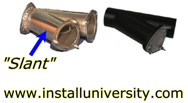
Notice the shape of the cutout is in the shape of a "Y". This is one example of an exhaust cutout. They all favor the basic shape shown in Figure 1.
The purpose of the exhaust cutout is to bypass the remaining exhaust system after the point at which the cutout is installed.
When you bypass the remaining exhaust system you are making it easier for the engine to get rid of the exhaust.
Therefore, you will gain horsepower and torque by making it easier for your engine to work.
The factory exhaust system is restrictive and holds back the full potential of it.
Example: Take a straw and blow through it as hard as you can.
Then open your mouth as wide as possible and blow as hard as you can.
Notice how much easier it is to exhale with your mouth wide open?
Think of your muffler as the straw through which your engine has to blow.
Now think of the cutout as the engine being able to open its "mouth" to exhale easier.
So how is the cutout shown in Figure 1 installed?
A local muffler shop will cut a section out of the existing exhaust pipe that runs back to the muffler the length of the cutout.
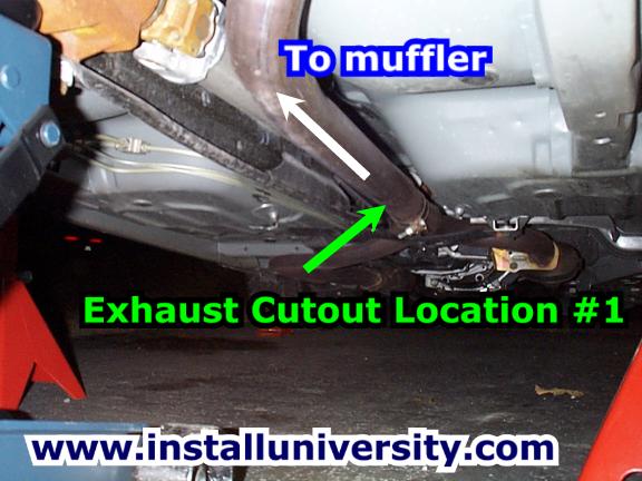
Most people place their cutout right after the exhaust pipe from the driver's side of the engine meets up with the exhaust from the passenger's side of the engine (see green arrow in Figure 2).
The cutout will be positioned so that the "Y" is inline with the pipe and the "slant" off the cutout is facing down toward the ground and the rear of the car.
Figure 2
The other place on the car to get an exhaust cutout installed is at the rear of the car just before the muffler (see blue arrow in Figure 3).
This style cutout can be made at the muffler shop (most common way) or you can have the exhaust shop install the cutout you purchased.
The same procedure for installing the cutout in the middle of the exhaust system is followed for installing the cutout at the rear of the car.
If the exhaust shop makes your cutout then they will take a small exhaust flange (every shop has flanges) and cut it to fit the pipe at an angle.
The flange should be inline with the pipe as it comes down over the axle getting ready to turn and enter the muffler.
They will then cut a hole out of the existing pipe and weld the flange to the pipe.
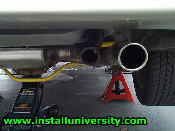
Your final result will look similar to the exhaust cutout in Figure 4.
You can see a view from further out behind the car in Figure 5.
Figure 3
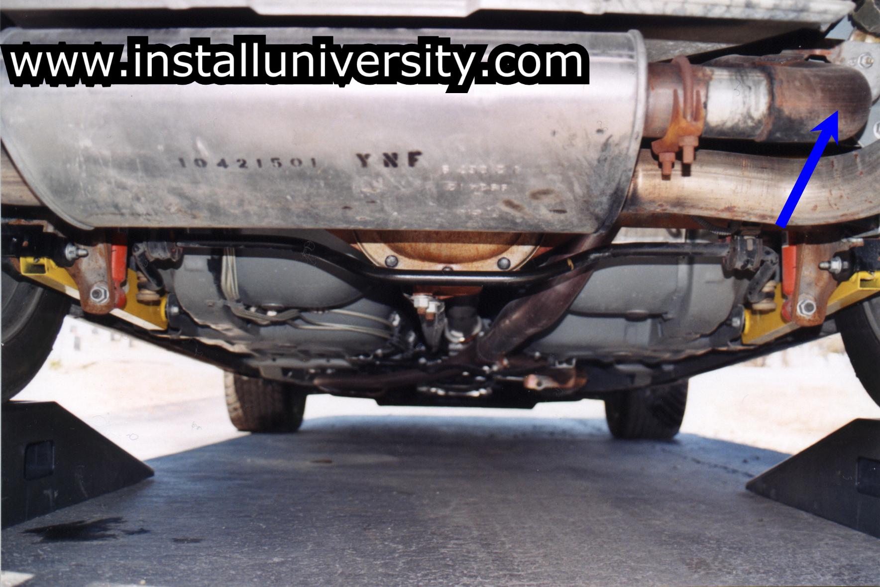
Figure 4
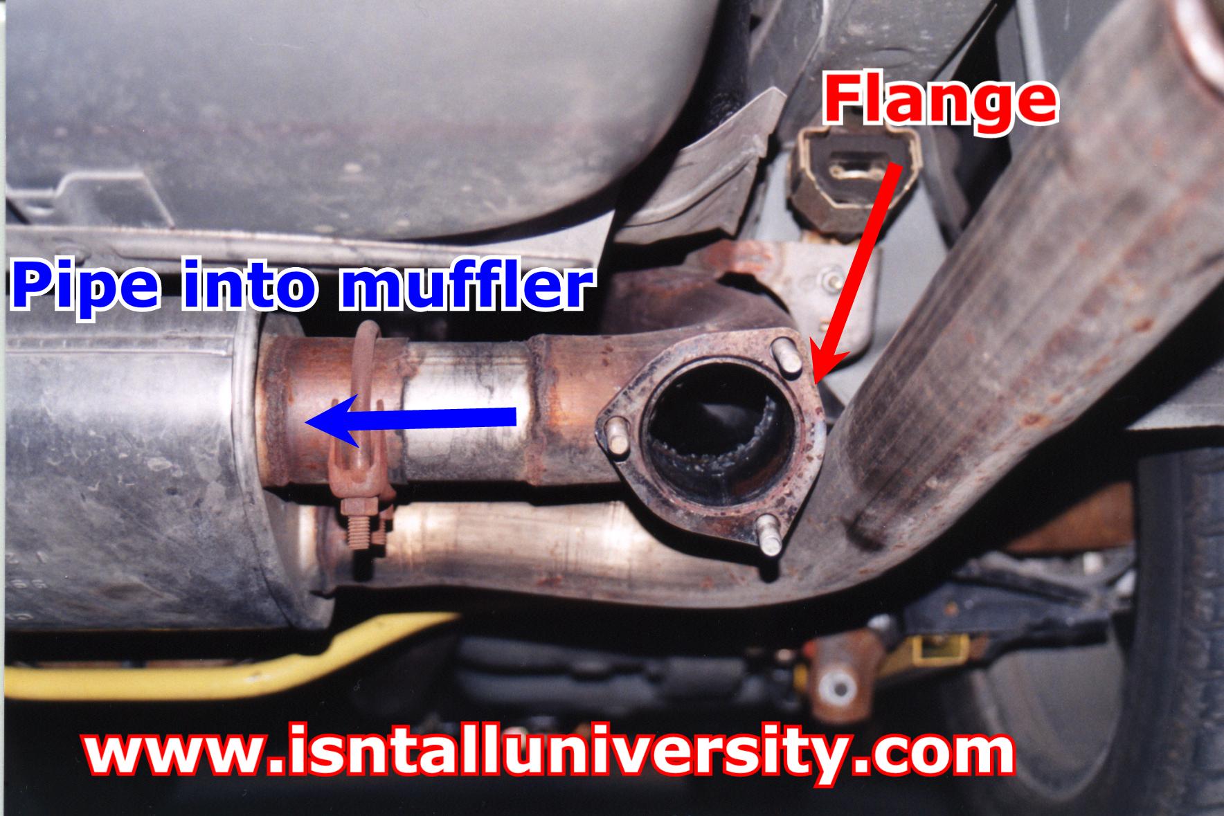
Figure 5
Shoot me a PM if you have anything additional to add to this.
*NOTICE*
If you are reading this and wondered why your cut-out thread has been locked here is why:
Purpose: The purpose of the document is to explain what an exhaust cutout is and its purpose.
Preface: This is an exhausted topic (no pun intended) that we hope we can shed some light on.
We start by showing several pictures of an actual exhaust cutout you can buy from many Sponsors ------------>
(see Figure 1) The cutouts are both made by Flow Tech.
Figure 1
Notice the shape of the cutout is in the shape of a "Y". This is one example of an exhaust cutout. They all favor the basic shape shown in Figure 1.
The purpose of the exhaust cutout is to bypass the remaining exhaust system after the point at which the cutout is installed.
When you bypass the remaining exhaust system you are making it easier for the engine to get rid of the exhaust.
Therefore, you will gain horsepower and torque by making it easier for your engine to work.
The factory exhaust system is restrictive and holds back the full potential of it.
Example: Take a straw and blow through it as hard as you can.
Then open your mouth as wide as possible and blow as hard as you can.
Notice how much easier it is to exhale with your mouth wide open?
Think of your muffler as the straw through which your engine has to blow.
Now think of the cutout as the engine being able to open its "mouth" to exhale easier.
So how is the cutout shown in Figure 1 installed?
A local muffler shop will cut a section out of the existing exhaust pipe that runs back to the muffler the length of the cutout.
Most people place their cutout right after the exhaust pipe from the driver's side of the engine meets up with the exhaust from the passenger's side of the engine (see green arrow in Figure 2).
The cutout will be positioned so that the "Y" is inline with the pipe and the "slant" off the cutout is facing down toward the ground and the rear of the car.
Figure 2
The other place on the car to get an exhaust cutout installed is at the rear of the car just before the muffler (see blue arrow in Figure 3).
This style cutout can be made at the muffler shop (most common way) or you can have the exhaust shop install the cutout you purchased.
The same procedure for installing the cutout in the middle of the exhaust system is followed for installing the cutout at the rear of the car.
If the exhaust shop makes your cutout then they will take a small exhaust flange (every shop has flanges) and cut it to fit the pipe at an angle.
The flange should be inline with the pipe as it comes down over the axle getting ready to turn and enter the muffler.
They will then cut a hole out of the existing pipe and weld the flange to the pipe.
Your final result will look similar to the exhaust cutout in Figure 4.
You can see a view from further out behind the car in Figure 5.
Figure 3
Figure 4
Figure 5
Shoot me a PM if you have anything additional to add to this.
Last edited by orangeapeel; 06-06-2006 at 07:46 PM.