
Port and Polishing heads.
 01-30-2011, 05:46 AM
#1
Ph.D. in HUBRIS
Thread Starter
iTrader: (11)
Join Date: Mar 2009
Posts: 3,964
Likes: 0
Received 0 Likes
on
0 Posts
I am getting ready to port and polish my 317s and I am looking for some info.
I plan to do them my self but would consider having them done professionally if I could get a reasonable price in my area. I know there is Kirt Urban? and someone else in the Detroit area that build LS motors. Can anyone help me find info to get ahold of them?
Again wanting to do them my self I would like to see pics of your ported heads. Professionally done or at home on your own all will be helpful. I have a complete and endless supply of free carbide bits, stones, and abrasive wheels at work. My plan is to take it slow and everything should turn out well. I have done a set of iron heads before just not aluminum.
If anyone know it would help, with these heads is is OK/common to take some of the length out of the valve guide? Many times people take them out completely to the top of the tunnel but don't know how well theses valves and heads like that. With my motor I will benefit from every cc I can flow through the head.
I ask anyone who is going to post, " DON'T PORT THEM YOUR SELF" to not chime in. I understand the time and meticulous detail needed to open the heads up. I am very confident with my take it slow and steady plan that I can make them all nearly identical and should be able to improve flow quite a bit.
 01-30-2011, 10:28 AM
#2

I didn't think it was that big of a deal, especially working with aluminum. The bowls were opened, chambers smoothed, casting removed.
I'll have no dyno comparison, but I'm sure that they breathe better.
Everything here was completed with a dremel w/extension & sandpaper.
Chambers smoothed like mirrors. There was lots of flash on mine.

Other than smooth around the guides, I didn't remove much material from them/didn't feel comfortable grinding them down not knowing exactly how much was structurally safe. Alot of flash removed from exhaust & intakes as well as opening up the areas behind each valve. There was no port matching. I didn't see the point being that I wasn't going for a 'Stage X' head.

The casting flash next to the intakes was indicative of the flash I took out everywhere.

I'll have no dyno comparison, but I'm sure that they breathe better.
Everything here was completed with a dremel w/extension & sandpaper.
Chambers smoothed like mirrors. There was lots of flash on mine.
Other than smooth around the guides, I didn't remove much material from them/didn't feel comfortable grinding them down not knowing exactly how much was structurally safe. Alot of flash removed from exhaust & intakes as well as opening up the areas behind each valve. There was no port matching. I didn't see the point being that I wasn't going for a 'Stage X' head.
The casting flash next to the intakes was indicative of the flash I took out everywhere.
Last edited by gMAG; 01-30-2011 at 05:18 PM. Reason: forgot pics!
01-30-2011, 03:47 PM
#4
TECH Enthusiast
iTrader: (10)

Join Date: Jun 2010
Location: Boston
Posts: 728
Likes: 0
Received 0 Likes
on
0 Posts

Hey man, im starting my heads today, i don't want to hijack but i figure you could use the answer to my question as well!
A porting dvd i have says to match the intake openings exactly to the gasket, i just want to make sure its ok to take off this much material? Im using felpro gaskets, and plan to slightly port the openings on the intake mani to match as well.
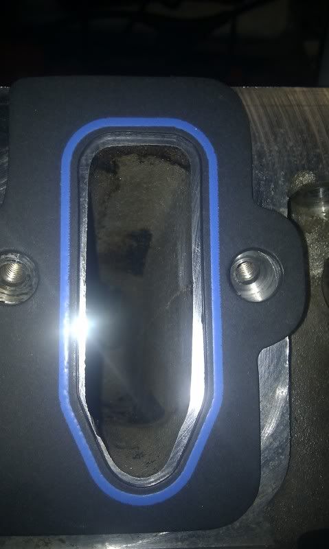
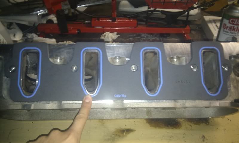
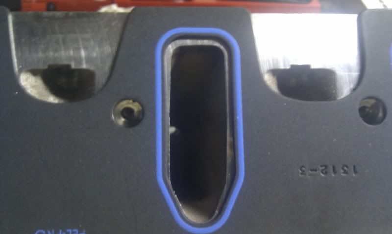
A porting dvd i have says to match the intake openings exactly to the gasket, i just want to make sure its ok to take off this much material? Im using felpro gaskets, and plan to slightly port the openings on the intake mani to match as well.
01-30-2011, 03:50 PM
#5
Ph.D. in HUBRIS
Thread Starter
iTrader: (11)
Join Date: Mar 2009
Posts: 3,964
Likes: 0
Received 0 Likes
on
0 Posts
Yes gasket matching is very common. You don't probably want to take that full 1/16 off the entire lenght of the runner but if you gasket match then open the tunels up some you should help your self out a lot. Just be carefull and go slow. Obviously much easier to take more out then put it back!
Trending Topics
01-30-2011, 07:13 PM
#8
TECH Fanatic
iTrader: (10)

Join Date: Aug 2004
Location: Rochester,Ny
Posts: 1,433
Likes: 0
Received 0 Likes
on
0 Posts
gasket matching is very common practice,but is not really a good practice.You want to match the heads to the intake,not the gasket.This old practice of gasket matching is not for the new lsx motors
01-30-2011, 07:24 PM
#9
TECH Enthusiast
iTrader: (10)
Join Date: Jun 2010
Location: Boston
Posts: 728
Likes: 0
Received 0 Likes
on
0 Posts
I figured i could match both to the gasket, get a win win. What would be the best way to match them. I'm half considering bringing my intake mani into work to photocopy the port and cut it out.
I guess i could use some paper and trace it out with a pencil.
I guess i could use some paper and trace it out with a pencil.
 01-30-2011, 08:01 PM
#12

Matching the head to the intake by enlarging the port openings on both surfaces is a bad idea. You end up creating a wide spot in the air flow path that will slow down airflow velocity right where fuel is injected into the airstream. This is never good.
01-31-2011, 06:51 PM
#15

You cant flatten the valve guides down to the roof of the port. You'd be burning oil in a month. They can, however, be narrowed up a bit, especially on the exhaust side. You can narrow up the tail that extends out behind the valve guides too but don't get carried away. It helps to direct airflow around the guide itself. The best thing we can do as amateurs is blend the bowls into the valve seats. I picked up 20cfm on a set of 243's with mild bowl blending, trimming the guides back a bit, and removing the rocker bolt boss.
01-31-2011, 07:25 PM
#16
Registered User

Join Date: Dec 2010
Location: South Carolina
Posts: 19
Likes: 0
Received 0 Likes
on
0 Posts
I've ported a few heads in my time and it's a bit of an art. Sometimes things that you think would work don't always work well. The safest thing to do is remove any parting lines or casting seems that will disrupt flow. Any sharp edge causes turbulence and should be blended. I typically look at the shape of the port and open it to the point that it straightens flow to the valve while minimizing contour changes. Playing around with the short turn can be disastrous if you don't what your doing so stay away from that. Raising port height is usually good but these heads have that already. So I would start by matching the intake to the head without making the area where they meet any larger than areas that follow in the head. Point here is to not slow velocity going into the port. Don't over polish the intake ports. If they are too smooth the fuel will want to separate from the air and ride the port walls rather than stay atomized in the charge. When you open the intake port, make sure you blend it back into the port so that the air doesn't accelerate around the turn near the push rod. Some people open the port causing a larger volume area near the opening compressing to a smaller volume area going into the port and around the turn. Not good.
You can narrow the guides down toward where the valve stem exits and blend it back toward the roof of the port. The valve pocket can be opened a little but don't over do it. You want a smooth radius to the valve seat area.
Make sure you blend the new matched opening on the intake manifold back into the runner so that there is a smooth transition.
Last of all, look at a set of CNC ported heads, measure them and copy.
02-01-2011, 07:39 AM
#17
TECH Enthusiast
iTrader: (10)
Join Date: Jun 2010
Location: Boston
Posts: 728
Likes: 0
Received 0 Likes
on
0 Posts
Ok guys i have a basic idea of what to do with the valve guide, but i have a more theoretical question. I've seen a sharper ridge around the valve guide and others that have a nice smooth one.
Wouldn't the sharper ridge create more turbulence by splitting the airflow much greater, than letting it take its own smoother path around the guide and over the swirl ridge? I personally feel like the first picture will net more mid-range power due to the swirl ramp and the smoother guide, and second more higher rpm power, but like bracketracer said "Sometimes things that you think would work don't always work well."
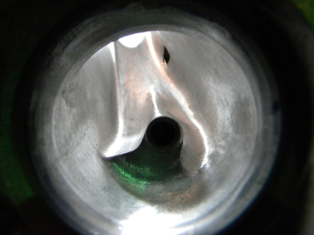
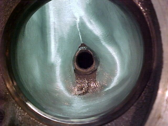
Wouldn't the sharper ridge create more turbulence by splitting the airflow much greater, than letting it take its own smoother path around the guide and over the swirl ridge? I personally feel like the first picture will net more mid-range power due to the swirl ramp and the smoother guide, and second more higher rpm power, but like bracketracer said "Sometimes things that you think would work don't always work well."
02-01-2011, 09:48 AM
#19
TECH Enthusiast
iTrader: (10)
Join Date: Jun 2010
Location: Boston
Posts: 728
Likes: 0
Received 0 Likes
on
0 Posts
Custm2500: i planned the first, although i have more of a high rpm goal, i feel the swirl ramp allows the air to flow around the valve into the cylinder better.
Im waiting on the mechanical engineer here at work to come in to ask about the airflow aspect of the ridge. The snow is holding him up.
Im waiting on the mechanical engineer here at work to come in to ask about the airflow aspect of the ridge. The snow is holding him up.
02-01-2011, 02:33 PM
#20
Ph.D. in HUBRIS
Thread Starter
iTrader: (11)
Join Date: Mar 2009
Posts: 3,964
Likes: 0
Received 0 Likes
on
0 Posts
Well it has begun!!!!! I started with the exhuast ports due to the question of sharp ridge or gut the intake as much as possible. I didn't take much out of the runner or exhaust outlet. I will take some out but wanted to study any pics a little further to get a good idea how much others opened them up. I took a ton of pics so here is the link to my album. They are all on the first page.
http://s111.photobucket.com/albums/n151/custmemaxx/
http://s111.photobucket.com/albums/n151/custmemaxx/