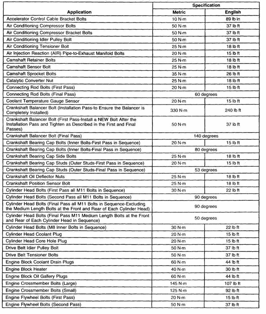
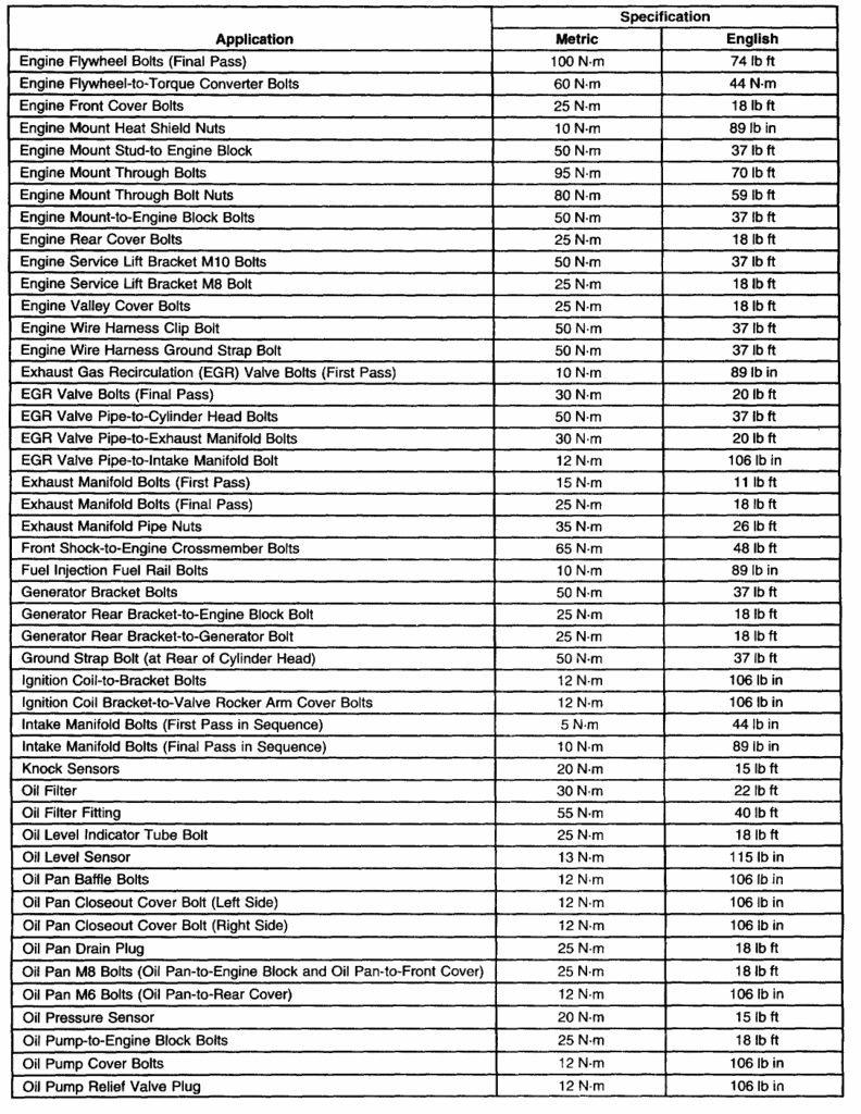
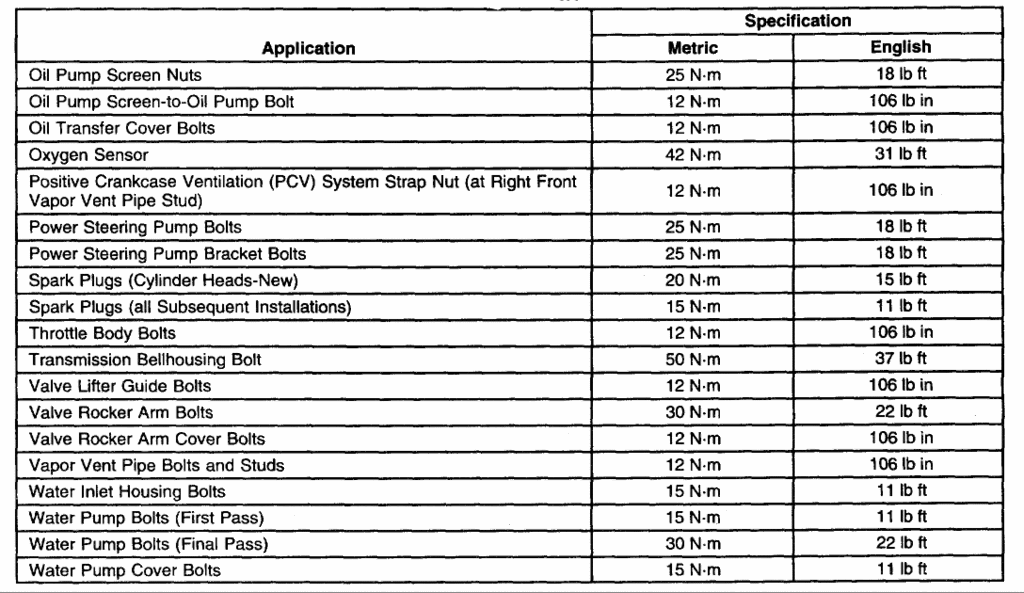
tourqe specs
#1
On The Tree
Thread Starter
iTrader: (105)
Join Date: May 2004
Location: Searcy Arkansas
Posts: 134
Likes: 0
Received 0 Likes
on
0 Posts
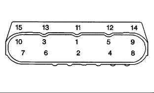
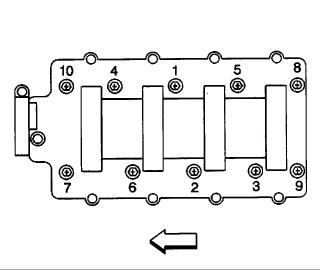
i am going to put my ls1 back together, what sequence do you go in on rods, mains ,a nd heads, is there a picture of what bolt is done first, any help would be nice, thanks
#2
TECH Regular
iTrader: (3)
Join Date: Sep 2005
Location: Its classified.
Posts: 450
Likes: 0
Received 0 Likes
on
0 Posts

From AllData:
Connecting Rod Bolts (First Pass) 15 ft.lb
Connecting Rod Bolts (Final Pass) 60 deg
Connecting Rod Bearing Bore Diameter 2.224 - 2.225 in
Connecting Rod Bearing Bore Out-Of-Round (Production) 0.00015 in
Connecting Rod Bearing Bore Out-Of-Round (Service Limit) 0.0003 in
Connecting Rod Bearing Clearance (Production) 0.0006 - 0.00248 in
Connecting Rod Bearing Clearance (Service Limit) 0.0006 - 0.003 in
Connecting Rod Side Clearance 0.00433 - 0.02 in
File In Section: 06 - Engine/Propulsion System
Bulletin No.: 99-06-01-011
Date: June, 1999
SERVICE MANUAL UPDATE
Subject:
Second Design Connecting Rod Bolt and Torque Specification
Models:
1997-99 Chevrolet Corvette
1998-99 Chevrolet Camaro
1998-99 Pontiac Firebird
1999 Chevrolet and GMC C/K Models (Silverado and Sierra)
with 4.8 L, 5.3 L, 5.7 L, or 6.0 L V8 Engine VINs V, T, G, U - RPOs LR4, LM7, LS1, LQ4)
This bulletin is being issued to revise the Fastener Tightening Specifications and the Piston, Connecting Rod, and Bearing Installation procedures in Section 6 Engine Mechanical of the Service Manual. A second design connecting rod bolt will be introduced for the 1999 model year. Either design bolt, (when used in pairs and properly tightened) may be used with 1997-99 connecting rods. Add the second design bolt description and torque specifications to the appropriate Service Manual information.
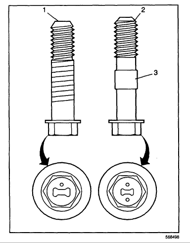
Identify the type of connecting rod bolt.
^ The first design connecting rod bolt (1) can be identified by a single dimple/mark on the head of the bolt and no retaining sleeve (3) on the bolt shank.
^ The second design connecting rod bolt (2) can be identified by two dimples/marks on the head of the bolt and a retaining sleeve (3) on the bolt shank.
Important : When replacing the connecting rod bolts, both bolts MUST be of the same design for each connecting rod assembly. The use of different design connecting rod bolts on the same connecting rod may lead to uneven clamploads and/or connecting rod bearing bore distortion.
Install the bearing, cap, and bolts.
Tighten
^ Tighten the first design bolts:
First pass evenly to 20 N.m (15 lb ft). Final pass to 60 degrees using the J 36660.
^ Tighten the second design bolts:
First pass evenly to 20 N.m (15 lb ft). Final pass to 75 degrees using the J
36660.

#4
TECH Regular
iTrader: (3)
Join Date: Sep 2005
Location: Its classified.
Posts: 450
Likes: 0
Received 0 Likes
on
0 Posts

When cleaning the thread bores for the head bolts in the block you can use some brake cleaner and suck it up with a shop vac. I prefer to tap the threads the problem lies in that most any hardware store including specialty fastener stores do not carry a tap in the correct pitch and size for the M11 bolts (2.75x11) if I remember correctly. I had a tap made so that I could do this. BE SURE TO CLEAN THE THREAD BORES so you get a correct torque on the head bolts.
#6
TECH Regular
iTrader: (3)
Join Date: Sep 2005
Location: Its classified.
Posts: 450
Likes: 0
Received 0 Likes
on
0 Posts

* Tools Required
* J 36660 Torque Angle Meter
Important:
* Crankshaft bearing clearances are critical. Excessive crankshaft bearing clearance may effect crankshaft position sensor signals and/or On-Board Diagnostics (OBD) II system performance.
* Crankshaft bearing caps must be installed to the proper location and direction.
* When installing the crankshaft bearings, align the locating tabs on the bearings with the locating notches in the engine block journal bore and the bearing cap.
* Always install crankshaft bearings with their machined partner. Do not file bearings or mix bearing halves.
* To prevent engine block oil leakage, install NEW M8 crankshaft bearing cap side bolts. The crankshaft bearing cap M8 side bolts have a sealant patch applied to the bolt flange.
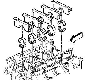
1. Install the crankshaft thrust bearings to the engine block and center bearing cap.
2. Install the remaining crankshaft bearings to the engine block and bearing caps.
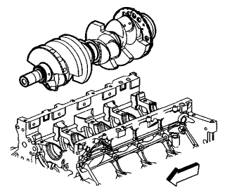
3. Lubricate the bearing surfaces and crankshaft journals with clean engine oil. Notice: To maintain proper crankshaft end play, use extreme care during crankshaft installation. Avoid scoring or damaging the thrust bearing.
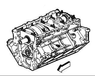
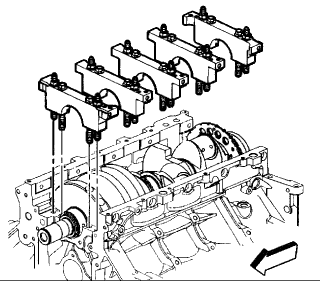
4. Install the crankshaft. Important: The bearing caps must be installed in the proper location and direction.
5. Install the crankshaft bearing caps (with bearings) into the engine block.
6. Start the M10 bolts and studs.
7. Tap the bearing caps into place with a plastic-faced hammer.
8. Install the NEW M8 bearing cap side bolts. Notice: Refer to Fastener Notice in Service Precautions.
9. Tighten the bearing cap bolts and studs.
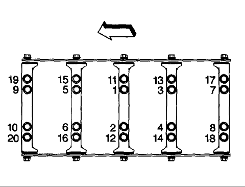
o Tighten the inner M10 bearing cap bolts first pass in sequence to 20 Nm (15 ft. lbs.).
Important: To properly align the crankshaft thrust bearings, the final thrust of the crankshaft MUST be in the forward direction.
10. Using a plastic faced hammer, tap the crankshaft rearward then forward to align the thrust bearings.
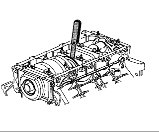
10.1. Tighten the inner M10 bolts final pass in sequence 80 degrees using the J 36660.
10.2. Tighten the outer M10 bolts first pass in sequence to 20 Nm (15 ft. lbs.) .
10.3. Tighten the outer M10 bolts final pass in sequence 53 degrees using the J 36660.
10.4. Tighten the bearing cap side M8 bolts to 25 Nm (18 ft. lbs.).
* Tighten the bolt on one side of the bearing cap and then tighten the bolt on the opposite side of the same bearing cap.
11. Install the crankshaft position sensor.
11.1. Inspect the crankshaft position sensor O-ring seal. If the O-ring seal is not cut or damaged, it may be used.
11.2. Coat the O-ring seal with clean engine oil.
11.3. Install the sensor. Align the notch in the sensor retaining bracket with the bolt hole in the block.
11.4. Install the sensor bolt.
* Tighten the crankshaft position sensor bolt to 25 Nm (18 ft. lbs.).
12. Measure the crankshaft end play.
12.1. Thrust the crankshaft forward or rearward.
12.2. Insert a feeler gauge between the center crankshaft bearing and the bearing surface of the crankshaft and measure the bearing clearance.
* The proper crankshaft end play clearance is 0.04 - 0.2 mm (0.0015 - 0.0078 inch) .
12.3. If the bearing clearance is not within specifications, inspect the thrust surfaces for nicks, gouges or raised metal. Minor imperfections may be removed with a fine stone.


