
PCV Setup - Concurrence/Feedback Desired
 03-04-2013, 12:29 PM
#1
On The Tree
Thread Starter
iTrader: (6)

Join Date: Jun 2007
Location: Cincinnati, OH
Posts: 128
Likes: 0
Received 0 Likes
on
0 Posts

So, after doing the research (a lot of conflicting stuff out there) I think this is how I want to do my PCV system, but was hoping for feedback from the 'experts'....
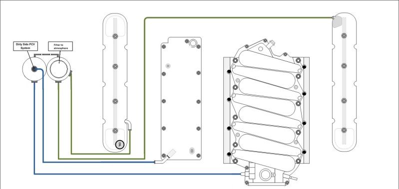
The thought behind this is that the valve covers will be the 'breathing' side of the system holding at or near atmospheric and the crankcase side would be held at a negative dP (lower pressure) being on the suction side of the intake.
The other differences/considerations were to have an oil cap breather filter (came with the Holley VCs I bought) and/or instead of a filter on that catch can, have it route to the intake side (pre "maf" I have in quotes since I no longer have a maf)... which theoretically is also atmospheric pressure. I have a NW102mm DB throttle body, so there is no routing to that 'port'.
Thoughts? Opinions?
 03-05-2013, 08:02 AM
#4
On The Tree
Join Date: Jan 2009
Posts: 194
Likes: 0
Received 0 Likes
on
0 Posts
I'm not feeling it. Are those catch cans? Is that a connection between the two cans? If so, you are running a more complicated open system that is necessary AND you will be allowing unmetered air into the intake, making your LTFT's go through the roof at/near idle. Also your vacuum source at the throttle body will just be pulling from the breather, not from the crankcase. If you want a true positive crankcase ventilation system you need to at least disconnect the two cans. Also, catch cans are designed to have an intake and an output connection. It appears you are using all connections as inputs on your "clean side" can.
03-05-2013, 08:18 AM
#5
I'm not feeling it. Are those catch cans? Is that a connection between the two cans? If so, you are running a more complicated open system that is necessary AND you will be allowing unmetered air into the intake, making your LTFT's go through the roof at/near idle. Also your vacuum source at the throttle body will just be pulling from the breather, not from the crankcase. If you want a true positive crankcase ventilation system you need to at least disconnect the two cans. Also, catch cans are designed to have an intake and an output connection. It appears you are using all connections as inputs on your "clean side" can.
As for the LTFTs, it won't matter since ALL air going into his motor will be unmetered...he's not running a MAF. Therefore, the air being introduced on the make-up side by the breather will be accounted for when tuned in speed density.
03-05-2013, 09:54 AM
#6
On The Tree
Join Date: Jan 2009
Posts: 194
Likes: 0
Received 0 Likes
on
0 Posts
Without a MAF this will work, but why? First, why no MAF? A speed density tune cannot adjust itself as well to density altitude changes as a MAF tune. And while you are getting true PCV to the crank case (a plus) you are also getting the oil laden air from the crank case introduced to the intake (a negative) as I have yet to see a catch can stop all the oil (I have tried 4 different ones). If I was to do it I would eliminate the clean side can, use the valve cover breathers as the air source and tie the lines from the valve covers to the crank case line.
03-05-2013, 10:14 AM
#7
On The Tree
Thread Starter
iTrader: (6)
Join Date: Jun 2007
Location: Cincinnati, OH
Posts: 128
Likes: 0
Received 0 Likes
on
0 Posts
Meent gets it.
As for why no MAF, a few reasons. 1) I have a very solid tune, have been doing this awhile, and I am comfortable, I will not be driving up and down mountains, so I am not worried about altitude changes... Weather is still compensated in the tune, but did take some time to get it right, where a MAF probably wouldnt have needed it.
why else? I didnt want the restriction of a MAF
Why else? I run EFI Live COS5, which forces you to stay in open-loop speed density.... and that is the catch-all.
I am NOT getting oil laden air into the intake, because i am using a proper catch can with a great filter on it. Look into All Angles Design. I am sure there will still be some smaller amount of oil particles in the air to get through, but much less than someone who slaps any catch can on.
I won't go into your suggestion, as it doesnt make any sense from a design standpoint (tying the clean side and dirty side together into 1 can). I know people do it, but that doesnt make it 'right'
Last edited by Juicedh22; 03-05-2013 at 10:36 AM.
Trending Topics
03-05-2013, 10:31 AM
#8
On The Tree
Join Date: Jan 2009
Posts: 194
Likes: 0
Received 0 Likes
on
0 Posts
I still think it's overly complex and the clean side can won't be doing much as it's at near atmospheric pressure on both sides. If you tie the valve cover lines into the crankcase line the clean side will be the breathers. Also, you are not getting oil laden air into the crankcase, it's already there. The purpose of a PCV system is to get rid of it. It goes into the intake where it reduces the octane of the fuel/air mix.
Maybe you don't get much DA changes in OH, we sure do! It can vary from 3,000 feet when it's cold to over 9,000 feet in the summer in ABQ.
I toyed with removing the PCV system on my Z06 but it does so much better than breathers at removing contaminants in the oil that I hooked it back up and use a catch can that does collect some of the oil, better than nothing.
Hope it works for you.
03-05-2013, 10:39 AM
#9
On The Tree
Thread Starter
iTrader: (6)
Join Date: Jun 2007
Location: Cincinnati, OH
Posts: 128
Likes: 0
Received 0 Likes
on
0 Posts
I typod, I should have said oil laden air in the intake... I want the clean side to be at atmospheric, thats the goal....
A CCV system is there to do more than just get "dirty air" out of the crank case, it is also there to keep the crankcase from becoming positively pressurized, which is a primary goal I have. Tying the VCs and the crankcase together, does not accomplish this goal.
A CCV system is there to do more than just get "dirty air" out of the crank case, it is also there to keep the crankcase from becoming positively pressurized, which is a primary goal I have. Tying the VCs and the crankcase together, does not accomplish this goal.
03-05-2013, 12:08 PM
#10

Intereresting as I proposed something similiar on another forum. My thought was to have the filtered air in front of the throttle body but in front of the MAF and air filter go to each valve cover. Then from the valley cover to the oil seperator and from there to the intake manifold behind the throttle body. Very similiar to what you are proposing. I see no reason why it would not work. Might work better than the factory routing.