427ci LS2 Sleeved, 4 barrel TB, port FI, NA, dry sump, engine build.
 05-13-2012, 02:30 PM
#41


Sweet dude. You are gonna have one bad *** car!!!
 05-13-2012, 10:53 PM
#42
Staging Lane
Thread Starter
Join Date: Apr 2012
Location: Pacific NW
Posts: 94
Likes: 0
Received 0 Likes
on
0 Posts

 06-14-2012, 01:38 AM
#45
Staging Lane
Thread Starter
Join Date: Apr 2012
Location: Pacific NW
Posts: 94
Likes: 0
Received 0 Likes
on
0 Posts
Hey guys... yeah I wish I was out driving the car... unfortunately the engine is still in the shop waiting for my custom wiring harness. The harness was ordered 3 months ago and is now six weeks past due. The harness is supposed to be here this week so if all goes well I will pick the engine up this Saturday.
Since my last post I have been working on the dry sump tank and plumbing. I ordered a Stef's dry sump tank that will be mounted in the trunk area. The tank is 3 gallon with 16AN fittings for return and 16AN into 12AN for the pump. I put the tank in the right side of the trunk area for better weight distribution and to keep things clean under the hood.
Also, I am working on setting up the ZR1 twin disk clutch with mechanical linkage instead of hydraulic, custom electric fan mount for the radiator, and cold air intake (cowel induction set up). I decided to go with cowel induction setup and a speed density tune for maximum HP. The two maf set ups I made were too restrictive.
When I get the engine back I'll post up some pictures of the install, the dry sump system, and cowel induction setup.
06-16-2012, 12:42 PM
#46
Hey guys... yeah I wish I was out driving the car... unfortunately the engine is still in the shop waiting for my custom wiring harness. The harness was ordered 3 months ago and is now six weeks past due. The harness is supposed to be here this week so if all goes well I will pick the engine up this Saturday.
12-05-2012, 01:32 AM
#47
Staging Lane
Thread Starter
Join Date: Apr 2012
Location: Pacific NW
Posts: 94
Likes: 0
Received 0 Likes
on
0 Posts
The rainy season is here now, so it�s a good time to follow up on this build thread. Since the last post in June I have finished installing the engine, trans, dry sump oil system, cooling, electronics, wiring, instrumentation and exhaust. I�ve had the car on the road since August and have several thousand miles of street driving, and some track time. During a track day in September I ended up seizing up 3rd gear on the main shaft of my Muncie transmission (the rear end locked up at about 80 mph).
It was a huge project to switch from the original carburated small block to the Gen IV LS engine. More than I imagined (time and money). The dry sump oil system added quite a bit of extra time to do all the plumbing. I�ll go through the process of installing the engine, computer, dry sump system�. and show pictures of how everything fit together.
I learned quite a bit about the dry sump system (tank installation, filters, and venting) for anyone interested in going to a dry sump.
In the end it has been totally worth it, I got what I was looking for. The new engine is amazing in comparison to the old small block. The engine starts easy, runs smooth, and the difference in power and acceleration is night and day difference
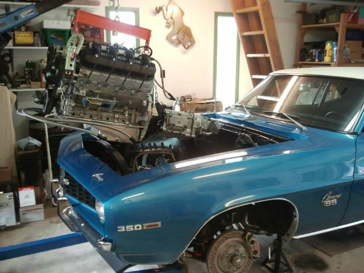
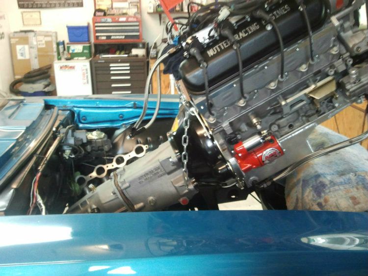
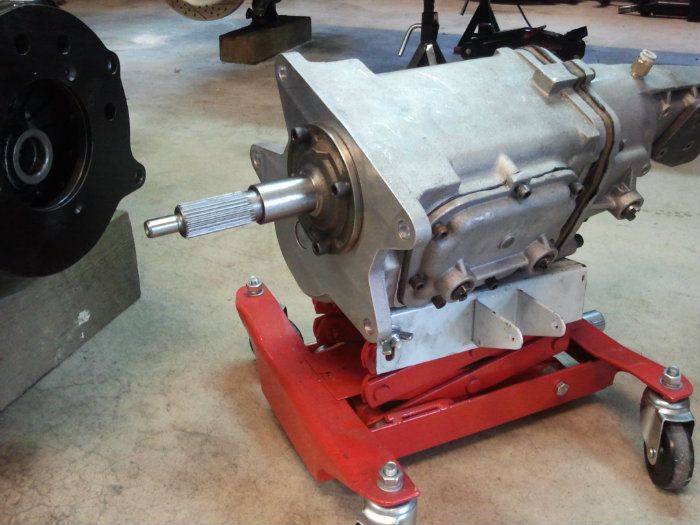
Tight fit with trans
It was a huge project to switch from the original carburated small block to the Gen IV LS engine. More than I imagined (time and money). The dry sump oil system added quite a bit of extra time to do all the plumbing. I�ll go through the process of installing the engine, computer, dry sump system�. and show pictures of how everything fit together.
I learned quite a bit about the dry sump system (tank installation, filters, and venting) for anyone interested in going to a dry sump.
In the end it has been totally worth it, I got what I was looking for. The new engine is amazing in comparison to the old small block. The engine starts easy, runs smooth, and the difference in power and acceleration is night and day difference
Tight fit with trans
Last edited by DaleTx; 12-29-2012 at 01:50 PM.
 12-05-2012, 04:06 PM
#50
Staging Lane
Thread Starter
Join Date: Apr 2012
Location: Pacific NW
Posts: 94
Likes: 0
Received 0 Likes
on
0 Posts
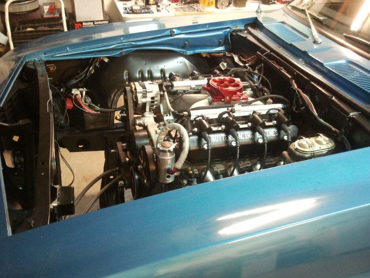
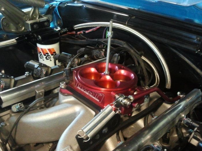
If you compare the new LS engine to my old 450HP carbureted small block. There is a difference of over 200 HP�. It is an absolute kick to drive now� whole different experience! There are no flat spots, no surging, no problems in hot weather. I should have done this conversion a long time ago. I will never go back to a carb set up.
The engine has smooth linear power from off idle to redline. The LS7 heads are great. They have a very unique sound when you get on it. I was worried about streetablity with the larger cam and single plane intake� no problem, very smooth and easy to drive.
I ended up going with a speed density tune.... no maf for now.
12-05-2012, 07:56 PM
#51
Staging Lane
Thread Starter
Join Date: Apr 2012
Location: Pacific NW
Posts: 94
Likes: 0
Received 0 Likes
on
0 Posts
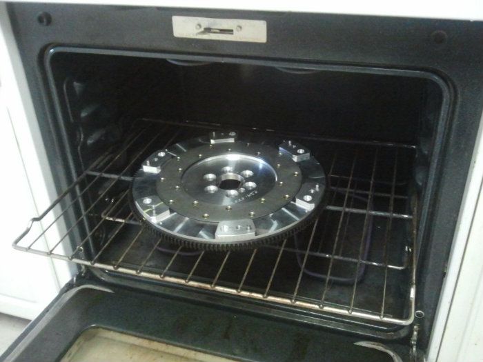
Aluminum flywheel and clutch install.
I have not used an aluminum flywheel before... there are some extra steps you have to take when installing. Since aluminum expands at a greater rate than steel.... the bore is a little bit tighter than on a cast iron or steel flywheel (the aluminum flywheel will not fit on the crank when cold). The manufacturer (Katech) recommended to heat the flywheel prior to installing on the crank.
I heated the flywheel up to about 250 degrees in the oven and then I was able to slip it on the crank... this worked good.
(sorry for the large pictures in the previous post... I got lazy and didn't re-size.... this size is better!)
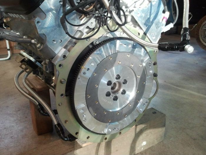
I purchased some ARP 12 point high strength bolts to attach the flywheel and they did not allow enough clearance for the clutch. I ended up having to buy the stock GM flywheel mounting bolts... they have a lower profile. The ARP bolts were just too close for comfort. The ARP bolts are shown in the picture.
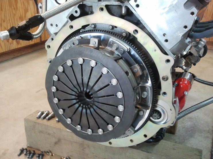
This time around I spent a bit of extra money and got a Corvette ZR1 twin disc clutch. On my previous build I used a Mcleod twin disc clutch. The Mcleod worked good for a while but as soon as it saw any abuse (slipping) and heated up, the floating disc tended to warp. When the floater disc warped then the clutch would slip under hard acceleration and also it became difficult to shift gears because the clutch would not disengage all the way. I went through three of these clutches in two years (had to be rebuilt... hassel).
So far the ZR1 clutch is proving to be the best clutch I've ever had. The floater disc is about 3 times thicker than the Mcleod unit. This does make the clutch heavier..... that's why I went with the aluminum flywheel to offset the extra weight. This new setup works great. Absolutely no slippage and a great feel.... very smooth.... no chatter whatsoever.
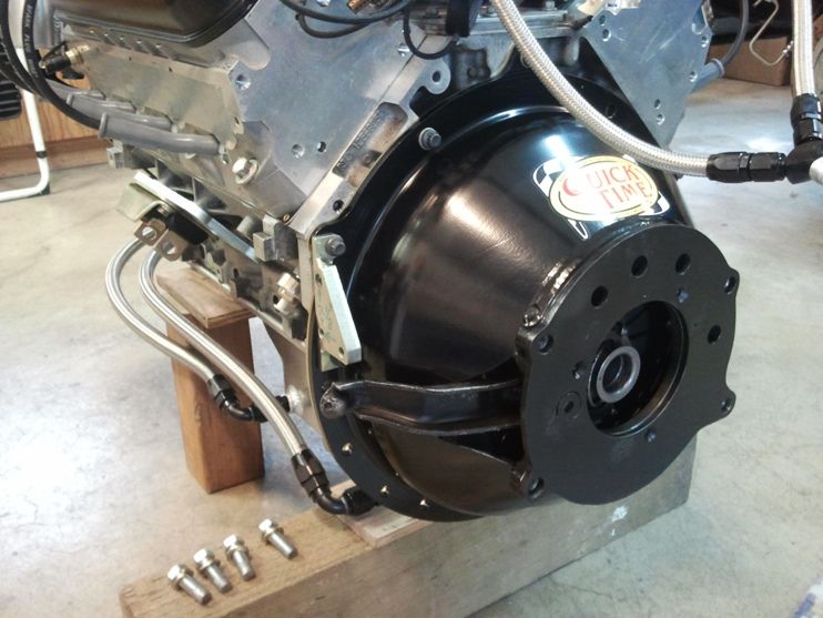
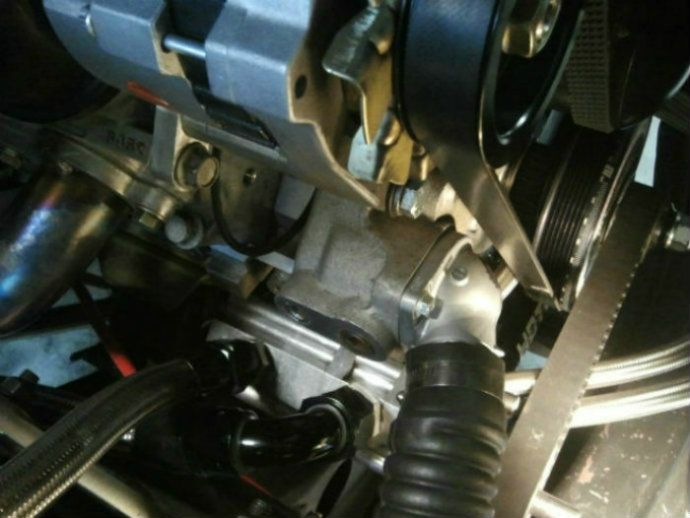
Bell housing installed with mechanical linkage.
Muncie transmisssion with heavy duty Autogear Supercase. The Autogear case is sturdier than the original case and rated for higher horsepower. I ended up siezing up this trans the first time on the roadcouse with the new engine. Previously I have done dozens of events with the old smallblock. When you add horsepower you find the weak link.
Thats all for now... next up will be the steam vent plumbing, radiator and fan set up. Hopefully this information is useful. I know I have picked up lots of info here on this site so now I am giving something back!

I have not used an aluminum flywheel before... there are some extra steps you have to take when installing. Since aluminum expands at a greater rate than steel.... the bore is a little bit tighter than on a cast iron or steel flywheel (the aluminum flywheel will not fit on the crank when cold). The manufacturer (Katech) recommended to heat the flywheel prior to installing on the crank.
I heated the flywheel up to about 250 degrees in the oven and then I was able to slip it on the crank... this worked good.
(sorry for the large pictures in the previous post... I got lazy and didn't re-size.... this size is better!)
I purchased some ARP 12 point high strength bolts to attach the flywheel and they did not allow enough clearance for the clutch. I ended up having to buy the stock GM flywheel mounting bolts... they have a lower profile. The ARP bolts were just too close for comfort. The ARP bolts are shown in the picture.
This time around I spent a bit of extra money and got a Corvette ZR1 twin disc clutch. On my previous build I used a Mcleod twin disc clutch. The Mcleod worked good for a while but as soon as it saw any abuse (slipping) and heated up, the floating disc tended to warp. When the floater disc warped then the clutch would slip under hard acceleration and also it became difficult to shift gears because the clutch would not disengage all the way. I went through three of these clutches in two years (had to be rebuilt... hassel).
So far the ZR1 clutch is proving to be the best clutch I've ever had. The floater disc is about 3 times thicker than the Mcleod unit. This does make the clutch heavier..... that's why I went with the aluminum flywheel to offset the extra weight. This new setup works great. Absolutely no slippage and a great feel.... very smooth.... no chatter whatsoever.
Bell housing installed with mechanical linkage.
Muncie transmisssion with heavy duty Autogear Supercase. The Autogear case is sturdier than the original case and rated for higher horsepower. I ended up siezing up this trans the first time on the roadcouse with the new engine. Previously I have done dozens of events with the old smallblock. When you add horsepower you find the weak link.
Thats all for now... next up will be the steam vent plumbing, radiator and fan set up. Hopefully this information is useful. I know I have picked up lots of info here on this site so now I am giving something back!
12-06-2012, 01:19 AM
#52
Staging Lane
Thread Starter
Join Date: Apr 2012
Location: Pacific NW
Posts: 94
Likes: 0
Received 0 Likes
on
0 Posts
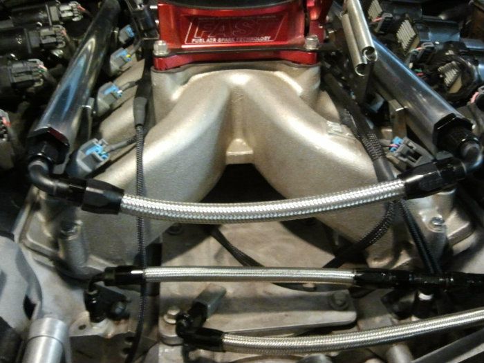
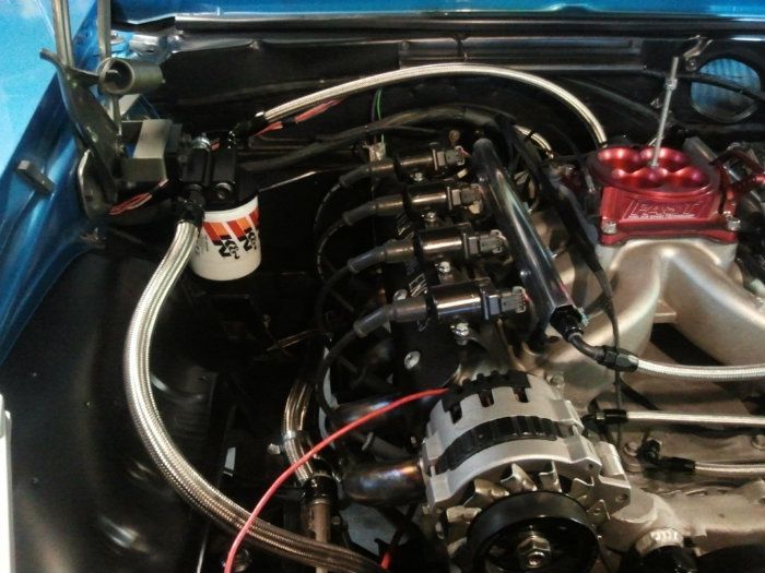
I did a lot of research on here and other sites regarding the steam vent plumbing. The steam vents are a nice feature on the LS block. On the gen 1 I used to take out the plugs on the front of the intake manifold when filling the block to let the air bleed out.
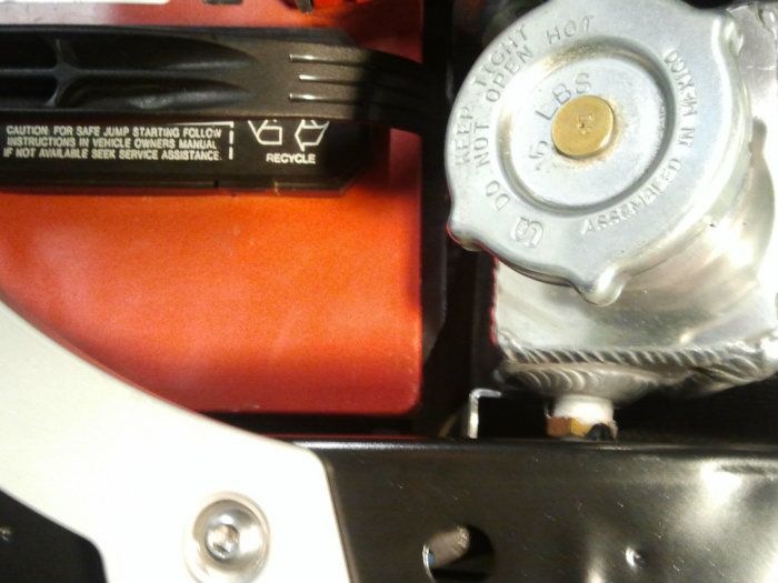
On the new engine the rear two vents are blocked off. On the front two vents I used 4 AN fittings (one 90 deg and one "T") then ran stainless braided hose over to the left fender.... through the core support and then over to the low pressure side of the radiator tank. I had an aluminum bung welded in two inches below the top of the tank for 1/8 pipe thread.... then I used a 4 AN fitting to complete the plumbing.
When I filled the engine with coolant you could hear the air come out of the tube as the block filled up. Once I topped off the fluid and put the cap on it was good to go. I never had to add any more fluid. The engine is angled back about 2.5 degrees (lower in the back) so I don't think it's a problem to plug the rear vents. Any air pockets should form at the front of the block.
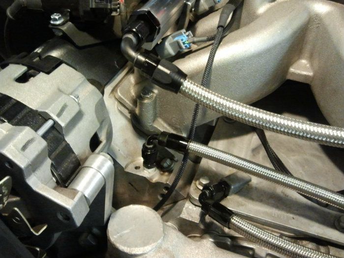
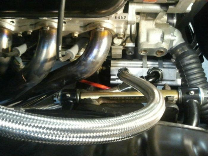
As a side note!!: Be sure to use the right size pressure rated hose for the pressure side of the power steering pump!! IT turns out that the stainless braided lines I used are rated for 1000 PSI, and the KRC power steering pump requires a 2,250 PSI rated hose (on the pressure side). When I had the car out on the road course last September the fluid was dripping out when I got back to the pits. The hose was barely hanging on. This was a big mistake on my part and I could have had a major fire if the hose had come off. The loose hose end was right next to the header. The new hose (black one) is rated at 2,500 PSI.
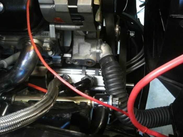
The hose on the upper right is the steam vent line and goes to low pressure side of the radiator and the line on the left comes from the vent on the valley plate. A little over kill on the air vent tank and filter but I already had the tank and mounting bracket so I used it. This engine actually pulls a vacuum because of the dry sump pump.
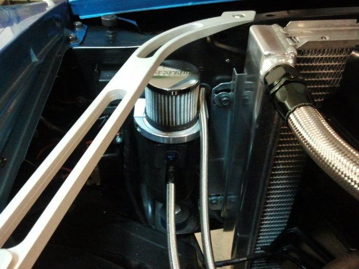
This is a shot of the bung I had welded into the low pressure side of the radiator tank.
I am new to setting up the LS engines, so if anyone sees any errors in this set up please let me know. I am always open to learn something new. Feel free to add information or pictures about your steam vent plumbing in the thread or any other information.
On the new engine the rear two vents are blocked off. On the front two vents I used 4 AN fittings (one 90 deg and one "T") then ran stainless braided hose over to the left fender.... through the core support and then over to the low pressure side of the radiator tank. I had an aluminum bung welded in two inches below the top of the tank for 1/8 pipe thread.... then I used a 4 AN fitting to complete the plumbing.
When I filled the engine with coolant you could hear the air come out of the tube as the block filled up. Once I topped off the fluid and put the cap on it was good to go. I never had to add any more fluid. The engine is angled back about 2.5 degrees (lower in the back) so I don't think it's a problem to plug the rear vents. Any air pockets should form at the front of the block.
As a side note!!: Be sure to use the right size pressure rated hose for the pressure side of the power steering pump!! IT turns out that the stainless braided lines I used are rated for 1000 PSI, and the KRC power steering pump requires a 2,250 PSI rated hose (on the pressure side). When I had the car out on the road course last September the fluid was dripping out when I got back to the pits. The hose was barely hanging on. This was a big mistake on my part and I could have had a major fire if the hose had come off. The loose hose end was right next to the header. The new hose (black one) is rated at 2,500 PSI.
The hose on the upper right is the steam vent line and goes to low pressure side of the radiator and the line on the left comes from the vent on the valley plate. A little over kill on the air vent tank and filter but I already had the tank and mounting bracket so I used it. This engine actually pulls a vacuum because of the dry sump pump.
This is a shot of the bung I had welded into the low pressure side of the radiator tank.
I am new to setting up the LS engines, so if anyone sees any errors in this set up please let me know. I am always open to learn something new. Feel free to add information or pictures about your steam vent plumbing in the thread or any other information.
12-06-2012, 03:14 PM
#53
TECH Apprentice
iTrader: (2)
Join Date: Aug 2008
Location: DC Suburbs
Posts: 305
Likes: 0
Received 0 Likes
on
0 Posts
Aluminum flywheel and clutch install.
I have not used an aluminum flywheel before... there are some extra steps you have to take when installing. Since aluminum expands at a greater rate than steel.... the bore is a little bit tighter than on a cast iron or steel flywheel (the aluminum flywheel will not fit on the crank when cold). The manufacturer (Katech) recommended to heat the flywheel prior to installing on the crank.
I heated the flywheel up to about 250 degrees in the oven and then I was able to slip it on the crank... this worked good.
(sorry for the large pictures in the previous post... I got lazy and didn't re-size.... this size is better!)
12-07-2012, 12:38 AM
#55
Staging Lane
Thread Starter
Join Date: Apr 2012
Location: Pacific NW
Posts: 94
Likes: 0
Received 0 Likes
on
0 Posts
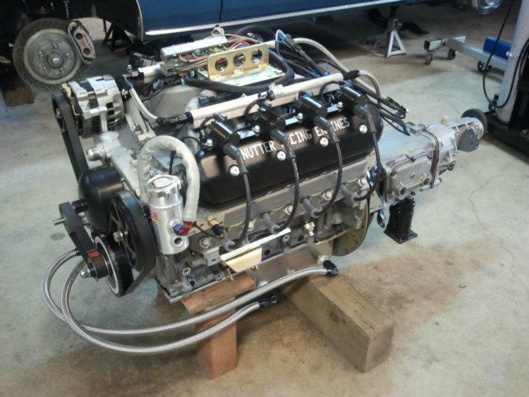
For this engine build I had the engine built from the ground up 100% complete from purchased parts. The engine builder started with a bare aluminum LS2 block and then did the machining and installed the sleeves. Then the rest of the engine was assembled including the dry sump pump system, electronic sensors, wiring harness and ECU.
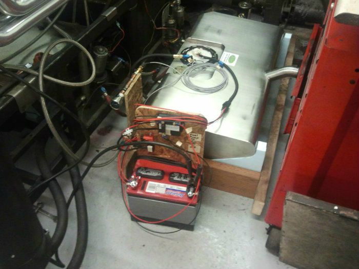
I put together the fuel supply system; CTSV fuel pump and Vaporworx digital fuel pressure controller... then I built a test stand with a 12 volt power supply, voltmeter, and fuel pressure gauge. When the engine was ready to go on the engine dyno I brought in the fuel tank and pump set up.
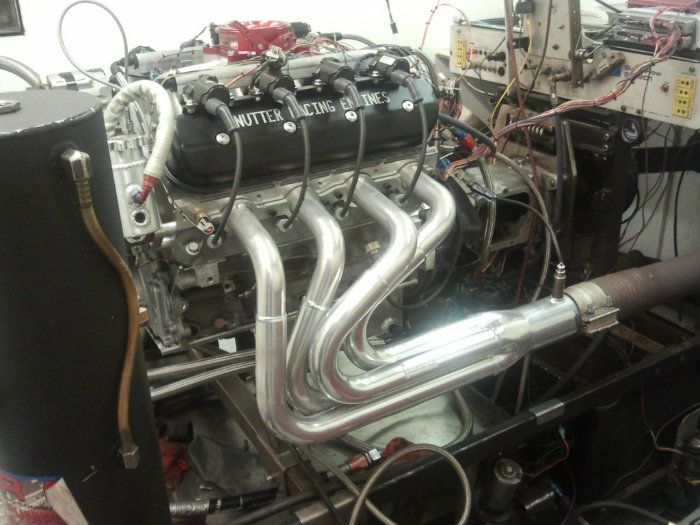
The engine was then tested and tuned on the dyno exactly as it would be set up in the car. I was able to measure the fuel pressure and voltage to the pump from idle up to redline at 7,400 rpm. I tested the fuel system while Brian Nutter put the engine through testing and dialed in the tune.
This was a great way to go..... I wanted to make sure once the engine was installed there would be no issues. It's just too much work to find out there is a problem after the install. When I cranked the engine for the first time after the install it fired instantly... no issues.
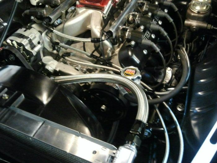
Here is a shot of the engine and fuel system during testing on the engine dyno
Fuel tank plumbed to engine with volt meter, digital controller, and pressure gauge
When I have done engine projects in the past I have always assembled the engine in the garage... roughed in the tune in the driveway and on the street, and then done the final tuning on a chassis dyno. Doing everything up front on the engine dyno was a great way to go! Not only is the engine tuned properly... but the engine is also broken in and rings seated.
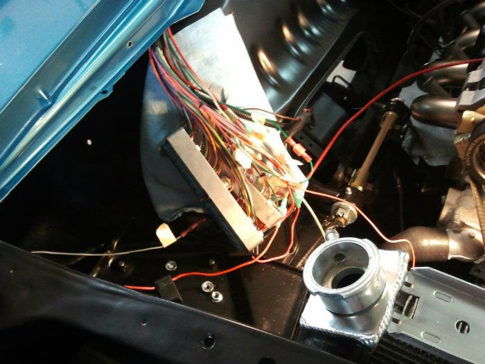
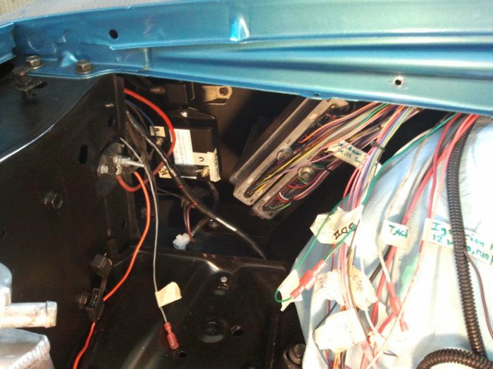
When I got the engine home I installed the ECU and fuel pump controller. I had labeled all the wires before we disconnected the engine from the dyno. This made it easy to make all the connections in the car. Here is a shot of the wiring harness installed inside right front fender and routed to firewall and behind the engine
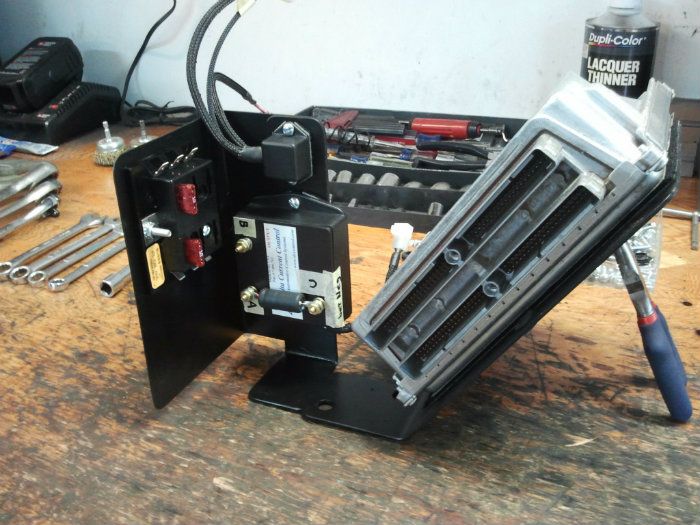
Home made ECU and fuel pump controller mount
The next post on here will cover the installation of the 4 stage dry sump pump, oil pan plumbing, remote dry sump tank and plumbing, remote oil filter, and breather system.
Installing the dry sump system in the car was a lot of extra work. I wanted to make sure that the engine always has a good oil supply whether I'm driving on the street, or on the track. The dry sump system worked out great. I run 5-30 weight synthetic oil (3 gallons). The oil pressure runs just under 60 psi while driving and jut under 40 psi at idle.
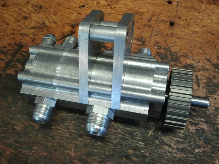
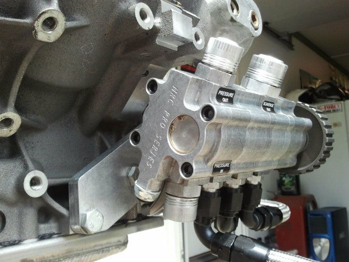
4 stage NRC dry sump pump
I put together the fuel supply system; CTSV fuel pump and Vaporworx digital fuel pressure controller... then I built a test stand with a 12 volt power supply, voltmeter, and fuel pressure gauge. When the engine was ready to go on the engine dyno I brought in the fuel tank and pump set up.
The engine was then tested and tuned on the dyno exactly as it would be set up in the car. I was able to measure the fuel pressure and voltage to the pump from idle up to redline at 7,400 rpm. I tested the fuel system while Brian Nutter put the engine through testing and dialed in the tune.
This was a great way to go..... I wanted to make sure once the engine was installed there would be no issues. It's just too much work to find out there is a problem after the install. When I cranked the engine for the first time after the install it fired instantly... no issues.
Here is a shot of the engine and fuel system during testing on the engine dyno
Fuel tank plumbed to engine with volt meter, digital controller, and pressure gauge
When I have done engine projects in the past I have always assembled the engine in the garage... roughed in the tune in the driveway and on the street, and then done the final tuning on a chassis dyno. Doing everything up front on the engine dyno was a great way to go! Not only is the engine tuned properly... but the engine is also broken in and rings seated.
When I got the engine home I installed the ECU and fuel pump controller. I had labeled all the wires before we disconnected the engine from the dyno. This made it easy to make all the connections in the car. Here is a shot of the wiring harness installed inside right front fender and routed to firewall and behind the engine
Home made ECU and fuel pump controller mount
The next post on here will cover the installation of the 4 stage dry sump pump, oil pan plumbing, remote dry sump tank and plumbing, remote oil filter, and breather system.
Installing the dry sump system in the car was a lot of extra work. I wanted to make sure that the engine always has a good oil supply whether I'm driving on the street, or on the track. The dry sump system worked out great. I run 5-30 weight synthetic oil (3 gallons). The oil pressure runs just under 60 psi while driving and jut under 40 psi at idle.
4 stage NRC dry sump pump
12-07-2012, 04:29 PM
#57
TECH Apprentice
iTrader: (2)
Join Date: Aug 2008
Location: DC Suburbs
Posts: 305
Likes: 0
Received 0 Likes
on
0 Posts
Thanks, it was about 3/4" lower when I got it but it was just too much of a pain to drive so I raised it a bit. Best combo of ground clearance and looks IMO right now.
Check my old threads, I've got one with a bunch of pics if you want to see more.
Check my old threads, I've got one with a bunch of pics if you want to see more.
12-16-2012, 04:56 PM
#58
Staging Lane
Thread Starter
Join Date: Apr 2012
Location: Pacific NW
Posts: 94
Likes: 0
Received 0 Likes
on
0 Posts
Going to a dry sump oil system on this build added quite a bit of extra $, and extra work to install. If I planned to only drive the car on the street I would have opted for a wet sump system. Since I will be running my car on the street and road courses (track day events) I opted for the dry sump system. The dry sump set up should make the engine live longer.
The advantage of the dry sump set up is that when you get into high G cornering.� left or right hand turns.� the engine always gets a good oil supply. With a wet sump pump.... the oil pick-up can become exposed (no oil) for brief periods during hard cornering, depending where the oil pick-ups located. Providing a constant oil supply to the engine under all conditions was the main reason I went with the dry sump system.
The dry sump pump is mounted outside the engine and is driven by a cog belt off the front of the crankshaft. This required a special crankshaft with an extended nose. The dry sump pump I used is a 4 stage pump. One stage is for pumping oil into the engine, and the other 3 stage�s are for sucking the oil out of the engine and returning the oil to the oil supply tank.
This shows the extra length on the front of the crank for the cog belt drive.
The line on the left is the pressure line that goes to a remote oil filter.
The line on the right is the main oil return line that goes to the oil tank in the trunk.
The pressure line into filter is 12AN.
The pressure line from filter into engine is 10AN
The oil goes into the port at the top of the block in the rear
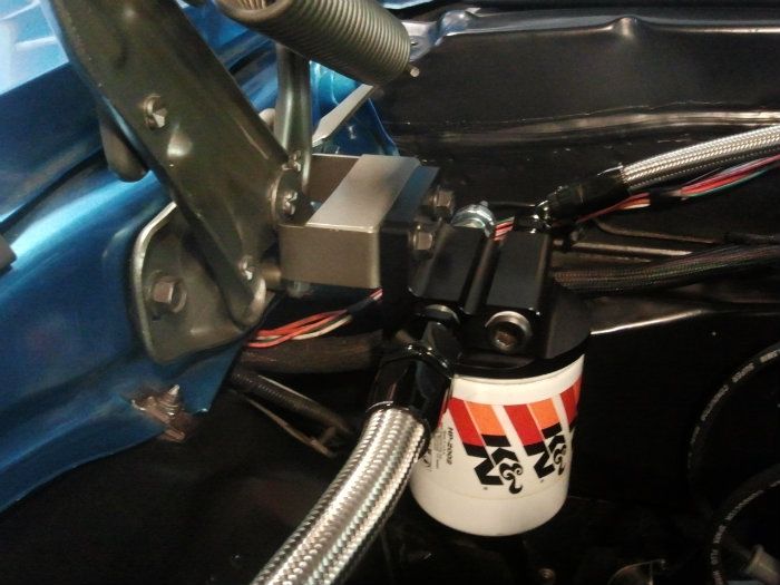
I plumbed in a pressure switch on the remote filter housing that will turn on a big red light inside the car if the oil pressure drops below 18 psi. If there is an oil leak or any other problem with oil pressure I will know right away. With this set up I don't have to monitor the oil pressure gauge while driving. I used the same size light as I used for the shift light.
The advantage of the dry sump set up is that when you get into high G cornering.� left or right hand turns.� the engine always gets a good oil supply. With a wet sump pump.... the oil pick-up can become exposed (no oil) for brief periods during hard cornering, depending where the oil pick-ups located. Providing a constant oil supply to the engine under all conditions was the main reason I went with the dry sump system.
The dry sump pump is mounted outside the engine and is driven by a cog belt off the front of the crankshaft. This required a special crankshaft with an extended nose. The dry sump pump I used is a 4 stage pump. One stage is for pumping oil into the engine, and the other 3 stage�s are for sucking the oil out of the engine and returning the oil to the oil supply tank.
This shows the extra length on the front of the crank for the cog belt drive.
The line on the left is the pressure line that goes to a remote oil filter.
The line on the right is the main oil return line that goes to the oil tank in the trunk.
The pressure line into filter is 12AN.
The pressure line from filter into engine is 10AN
The oil goes into the port at the top of the block in the rear
I plumbed in a pressure switch on the remote filter housing that will turn on a big red light inside the car if the oil pressure drops below 18 psi. If there is an oil leak or any other problem with oil pressure I will know right away. With this set up I don't have to monitor the oil pressure gauge while driving. I used the same size light as I used for the shift light.
12-16-2012, 06:46 PM
#59
Staging Lane
Thread Starter
Join Date: Apr 2012
Location: Pacific NW
Posts: 94
Likes: 0
Received 0 Likes
on
0 Posts
Another advantage of a dry sump pump system is that there is no oil sloshing around inside the oil pan. The dry sump pump creates a vacuum inside the crankcase and sucks the oil out that gathers at the bottom of the pan. My set up has two oil pick-ups on the left side of the pan, and one on the right side. Whether I�m in a hard left hand turn or hard right hand turn, the oil gets picked up and returned to the oil tank.
This set up also keeps oil from splashing up on the crank counterweights while cornering or braking. No windage tray or crank scraper is required. Keeping oil off the crank is also good for a little extra HP�. I'll take it
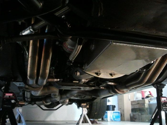
My engine builder (A.C. Nutter) provided a custom oil pan for my engine designed to fit my car. I took the measurements and they built the pan. They purchased a Canton fabricated aluminum oil pan, modified it, and then added the bungs for the oil pick-ups.
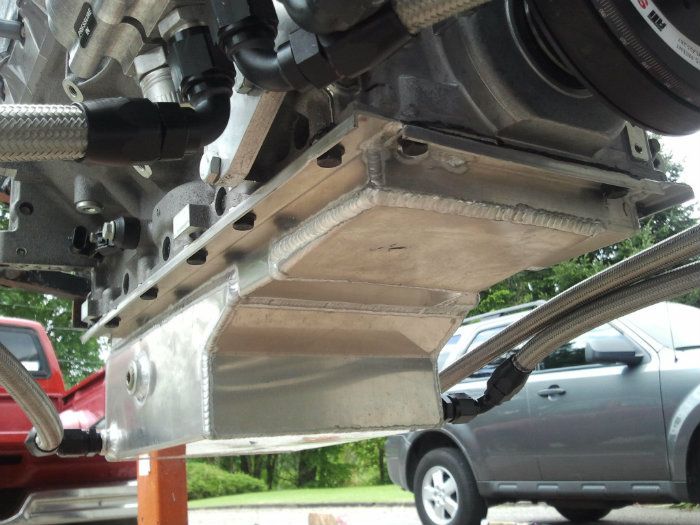
Installed in car... Right side oil pick up.
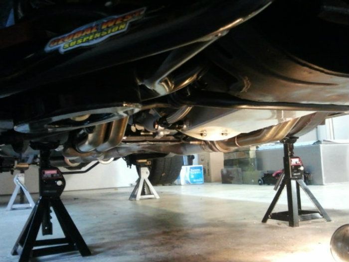
Left side oil pick ups
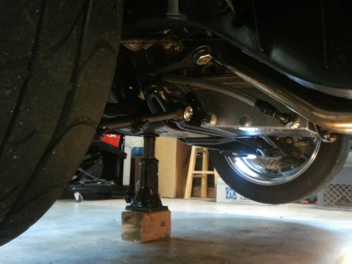
The pan has a nice low profile and fits up above the sub-frame cross member and steering tie-rod.
This set up also keeps oil from splashing up on the crank counterweights while cornering or braking. No windage tray or crank scraper is required. Keeping oil off the crank is also good for a little extra HP�. I'll take it
My engine builder (A.C. Nutter) provided a custom oil pan for my engine designed to fit my car. I took the measurements and they built the pan. They purchased a Canton fabricated aluminum oil pan, modified it, and then added the bungs for the oil pick-ups.
Installed in car... Right side oil pick up.
Left side oil pick ups
The pan has a nice low profile and fits up above the sub-frame cross member and steering tie-rod.
