Install help on my aps asap..!
 10-18-2008, 02:49 PM
#1

Ok was going to start putting the turbo assemblies and stuff together.
So pulled out think lhs turbo..they really should mark the parts but at least have pics and stuff to figure things out and it is a good installation guide..well pretty good.
So left hand turbo..I put in the two water inlets,outlets whatever on each side and they are the ports under the screwed in hex plugs. They fit perfectly no problem.
Then go to right side turbo and seems now the hex plugs are reversed they are in the farther away from the drains holes. So you are supposed to screw in the water inlets,outlets to the holes close to the oil drain?
Problem they are not going in there worth crap..might be just threads in the one hole but wondering have the plugs been put in wrong holes.??
I guess pics are easier to explain this stuff. I am looking thru the manuals and the lhs on the manual is very clear with many good pics so sure its right but the rhs mabye is wrong..maybe even aps is using the wrong holes..After all why would they use different holes if its same turbo? those farther from the oil return are water..the oil is another place like on top and what the hell are the hex head holes about..they seem not thru like the water holes on the lhs turbo.the holes that are open on the left hand side are blocked with restrictors or something..
Maybe this is why some are dying..maybe someone is using the wrong holes or the guys at factory are using the wrong ones. Course the threads could be messed bad if the hex plugs are in the wrong holes.
Maybe someone can clear this up..Seems I can't get a break lately with this stuff. Some clear pics of the proper holes to use would be appreciated.
My garretts are so simple..you have oil and water port and thats it.
Why four holes on this thing..are these actual 20gs?
 10-18-2008, 03:33 PM
#2
Figures my camera is dead..Anyone that hasn't installed your aps turbos can take a pic of them showing which ports have the hex plugs in them. On the gto and corvette they seem to have pressed in plugs. I suspect the pressed in plugs are extra oil ports or something they seem to have a plug and restrictor hole or something in those ports.
The water ports on the lhs turbo are wide open on plug looking thing and no restrictor.
I may have to use my macro lense.
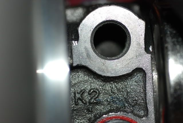
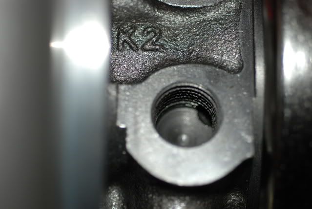
I don't understand these are all water feeds so why would they look different inside the housing is same..k2 . So seriously have to wonder if people are using the wrong ports?
The pictures are not so good and has anyone had trouble with the fittings not going in . Maybe thats cause the holes are not the right ones for size,thread. The oil feed holes are very different of course much smaller so no problem there. I am used to normal turbo housings.you have oil feed, you have big oil return ,you have coolant in and coolant out.So whats with all these darn holes is it cause they are twins and get daisy chained?
But still why the restriction looking holes and why don't the fittings go in there nicely?Threads look ok and its not the fittings they work fine in the other turbo..
I could chase the threads or something but more worried this is sometime serious possibly accounting for some dead f body turbos. Maybe starving the turbo of coolant by using those blocked looking ports.
Well at worse will have some pics in hour or so when battery camera charges up.
The water ports on the lhs turbo are wide open on plug looking thing and no restrictor.
I may have to use my macro lense.
I don't understand these are all water feeds so why would they look different inside the housing is same..k2 . So seriously have to wonder if people are using the wrong ports?
The pictures are not so good and has anyone had trouble with the fittings not going in . Maybe thats cause the holes are not the right ones for size,thread. The oil feed holes are very different of course much smaller so no problem there. I am used to normal turbo housings.you have oil feed, you have big oil return ,you have coolant in and coolant out.So whats with all these darn holes is it cause they are twins and get daisy chained?
But still why the restriction looking holes and why don't the fittings go in there nicely?Threads look ok and its not the fittings they work fine in the other turbo..
I could chase the threads or something but more worried this is sometime serious possibly accounting for some dead f body turbos. Maybe starving the turbo of coolant by using those blocked looking ports.
Well at worse will have some pics in hour or so when battery camera charges up.
10-18-2008, 03:58 PM
#3
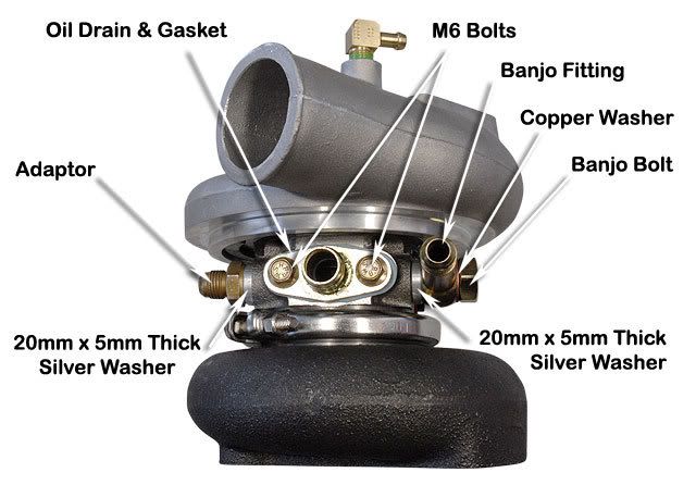
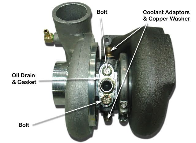
left hand side gto..just like my one lhs.notice the water fittings go into the holes one down from the oil return and nearer the oil feed on top of the housing. The hex plugs are in the holes close to the oil return.these holes are not coolant holes. Bet a million bucks..not sure what they are for.be nice if Peter chimes in here and explains this .
Ok on the rhs gto its flipped over but you can see that again the water lines go into the holes farther away from the oil return. It makes sense since the turbos and housings are identical to our f body.
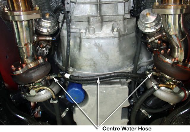
In this picture you are seeing if you hit magnify or enlarge the pic that both turbos are using the same holes.coolant is just going into the one turbo out and across to the other turbo and then out to the head. Both feeds are into the same holes and both plugs are in the holes closest to the drain feeds.
So plugs in mine are in the wrong holes..! now question is how tight are they and are they going to come out without problems. I am trying to do my install and have the wrong holes plugged. Now maybe they are loose didn't try yet those plugs can strip so easy and not sure where can get them. And think they must be special high heat sealer.
SO and the big SO..how many of you f body guys have those plugs in the wrong holes and is that the cause of some dead turbos..The gto guys and vette guys so far don't seem to have near the problems..
Oh also checked sort of my shaft play..seems ok. Unless the turbos actually hit the housing and destroy themselves will run them till they drop and then rebuild with better wheels. But if they are not getting proper coolant that could be a big factor in failure don't you guys thing..
Someone is asleep at the wheel at aps factory putting in those hex plugs. Or as said has anyong removed a hex and reinstalled and did any of you find your water fittings were not going in very good?Did you force the fitting in there and was that one of your dead turbos..Actually being daisy chained not sure what the wrong holes would do.It might kill the feeding turbo or the fed turbo..no idea.. Normal mits are not set up like this..
They could have just used normal housing and y lines I think no freaking idea what those extra weird looking inside inlets.outlets do.
And repeat if anyone that hasn't installed could post some pics lets see if yours are also screwed up.
10-18-2008, 04:13 PM
#4
Ok can post some f body pics and they are reversed on the f body! So that means that maybe they are both cooling ports but not sure why the inner ones look different when you look in. So they can maybe use whatever one is best in the postion and stuff ,routing of the lines and oil lines..so double coolant fittings.Makes some sense as they are completely different hole size then the oil feeds.
Ok then guess I need to get may holes retapped as have a problem with them but maybe shouldn't take out plugs they might strip or they might not seal well again
So would still like Peter to please reply if they are indeed dual water feeds on both sides.
And if there is any effect from using one hole or the other..
Now guess assemble my one side for now but still be a bit pissed if have to retap out think both holes on that one. Guess not the end of the world.machinist was maybe hung over that day!
 10-18-2008, 04:23 PM
#6
I would appreciate knowing what tap to use if need be to clean these threads out.
Well if they are dual feed then guess their goes my theory of what was maybe killing some of the turbos. Back to maybe the inlet collapsing theory on those..much more f body problems then gto or vette it looks like.
And collapsing tubes will for sure make turbos blow oil out the back..
And how many have actually totally failed..no boost or hitting the housings ?
Maybe not that many,most were fixed for oil out the back??
Also looks like intstructions for pcv are not right for 98.99 cars..?Crankcase ventilation can also cause oil out the back as well. Usually that problem goes away when ventilation is repaired. Had it happen several times on my talons with mits turbos and no ill effects when solved the exceessive crankcase ventilationi problem. It was pcv related.
Trending Topics
 10-19-2008, 10:34 AM
#9
Sorry I am hyper to get an answer on this question since doing my install now.
It looks like every f body kit has the rhs coolant lines into the holes close to the coolant return while the c5,gto and g8 don't and use the farther from the oil return lines on both left and right turbos.
I did manage to take out a plug and it wasn't hard to do so could likely switch to the farther holes as well.
I wouldn't be worried if the holes were the same but if you look into the rhs f body holes and then look into the left hand side f body holes you will see that on the left its pretty much a staiight in hole..on the right the holes look more dead headed but with some little hole in the side of the shaft..again not describing too good.
I may try to get a pic today of what I mean.
We have fair amount of aps guys running hooked up like this in the f bodies but we have seen some f body failures but not read about hardly any gto,c5 or g8 failures. I realize some problems in the f body are likely due to the intake tube thing but some might be do to this water line connection isssue in the f body.
If either port works then would still like to understand the difference in way they look. Can't see that close to drain hole port working that great.
If do use those icloe to drain ports then looks like need to retap the holes or threads on my fitting as seems to not want to go into there very good.
10-19-2008, 10:55 AM
#10
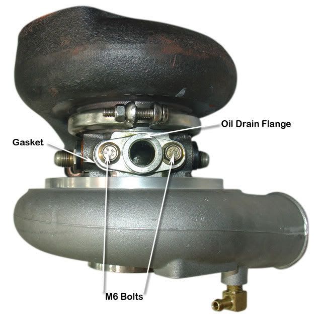
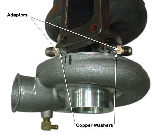
Ok so there are no torque specs on almost every place and fitting that uses the copper washers.
so just make those "tight" is the key not too tight or too loose. A bit vague torque specs are so much nicer and more precise.
Could I use high temp permatex thread sealer along with the copper washers on the fittings or will the heat from the turbo just melt off the permatex sealer. I have read how some have some leaking at the fittings and don't want any and understand it might be pretty hard to get to some of the fittings when installed in the car.
It looks like head bolt retorque will not be possible without removing the aps manifolds at least on the drivers side havent' put the passenger side up to the block yet.
Later today.