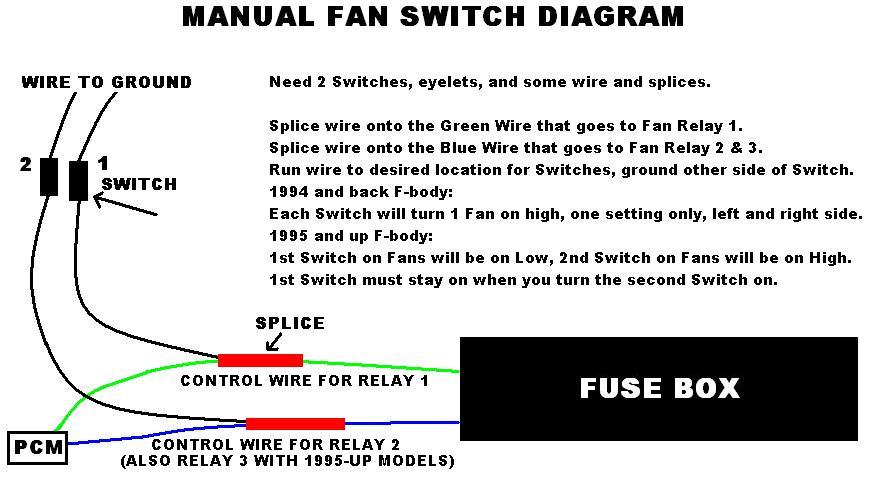
Manual Fan Switch Diagram
 01-25-2009, 01:00 PM
#1

Figure this can help some people out..
I currently have my Fuse Box setup with only 2 Relays, I re-built it cause the LT1 PCM stopped sending the signal to turn the Fans on. Then I used the Fan Wiring for some of the circuits for the LQ4 Swap.
I plan on tearing down the Wiring from the Wheel Well Harness Connectors all the way to the Fuse Box, cleaning it up and re-wiring everything the way it should be. I'll also be adding in a couple of Fused Circuits I need to make the LQ4 Swap run a little better.
The LS1 PCM will be able to send the signals for the Fans, so I am going to wire them again and build the 3-Relay setup for them. I'm also keeping my Manual Switces in the car, wiring them into the Fan Relay Control Wires to have a Manual backup.
It will take some time, but it will be done right.
 01-25-2009, 01:10 PM
#2
Should help some people, I think Shoebox's(I know you are on here now, thanks for your site!) diagram screws some people up due to the optional LED lighting.
Surprised you didn't use a double pole double throw switch so you would only need one switch. Your stuff is always really clean though, did you make a switch panel anywhere?
I used the one switch method and installed it in the lighter panel. They changed the fans in the tune though and the low speed is on almost all the time though, guess unless I have that changed I have no use for my fan switch anymore.
01-25-2009, 01:24 PM
#4

Currently with mine I have 2 Switches so I could control each side, that way if one of the Relays went out I could tell.
Yea, I have a little mounted Switch Panel, it's on the driver's side about 6" under the left Heater Vent. I made it out of some 1/16" Aluminum that I had left over from my AC Delete Panel. I was going to get rid of it, but I said F it and decided to keep it and wire it in clean since I'm going to be stripping all that apart and re-building it.
The main reason is cause I'm not too sure if my PCM has the Fans tuned out, so I'll have the Manual Switches just incase the PCM doesn't turn them on when I have everything re-wired and the car is together running.
Then when I get it Tuned for the T56 I'll have the Fans set, and still have a Manual Backup if needed.


