
Need a bit of wiring help,read stickies twice
 08-08-2009, 10:09 PM
#1
Launching!
Thread Starter
iTrader: (6)

Join Date: Nov 2003
Location: Boynton Beach
Posts: 210
Likes: 0
Received 0 Likes
on
0 Posts

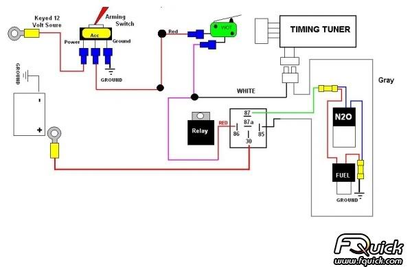
I'm trying to figure out how to add a Dynotune lean shutdown switch to the diagram above. I have a FPSS inline on the grey wire coming from timing tuner.According to Dynotunes instructions I need to put their White/yellow wire on pine 85 of the relay as well. Does it just splice into the grey wire after the FPSS?
Second problem is that the Timing tuner Instructions say to remove chasis ground for NOS relay and attach the Gray wire . Is that's what's shown above, and I can just splice in my yellow shutdown wire?I have about 20 hours installing this NX wet kit,heater,wideband and now these two problems. I think I could have done a heads and cam swap in half the time so far.In the morning I'm rewiring the stuff in the enging compartment. I made a couple mistakes I want to fix.First is that I didn't feel like running out to get multiple wire colors, I had a spool of red so I used it. It makes it way to confusing with all red wires..DOH!.Getting colored wire tomarrow.Second mistake was tidying everything up and putting on plastic tubing over everything before doing ALL the wiring and testing.It's coming off tomarrow too.
Anyways if anyone could explain this it would be greatly appreciated.
 08-09-2009, 12:47 AM
#2
10 Second Club

First, a comment concerning wire colors. Using multiple colors will help make sense of your circuits but it is also a good idea to follow common conventions such as using red for positive (power) and black for negative (ground). Colors for other electrical functions are more flexible.
You need to understand your circuit. In order to understand your circuit, you need to know the pin assignments of the standard automotive relay in your diagram. You need to know that pins 85 and 86 are the coil, and pins 87 and 30 are the contacts. Without this information, you can’t follow the circuit. If you keep this information in mind, the circuit is fairly simple. Your system will spray when relay contacts 87 and 30 close and make a path for current to flow from the battery, through the solenoids, to ground. The relay contacts close only if current flows through the relay coil, pins 85 and 86. The key to understanding the circuit is to know when current flows through the relay coil. Current flows through the relay coil when power is applied to pin 86, and pin 85 is connected to ground – both conditions must be simultaneously met. Pin 86 receives power only when your system is armed and the WOT switch is closed. So, the final key is connecting pin 85 to ground. In your circuit, the Timing Tuner connects pin 85 to ground through the grey wire.
There are various ways to add additional safety devices to your basic circuit. I'm not familaiar with the dynotune lean shutdown but it would be a mistake to connect pin 85 to ground through another (parallel) path. Good luck.