2 stages Nitrous wiring
 01-05-2010, 01:34 AM
#1
Teching In
Thread Starter

Join Date: Aug 2007
Posts: 19
Likes: 0
Received 0 Likes
on
0 Posts
Hi, im putting togheter my nitrous system with 2 wet stages and controlled by the microedge and using a stand alone for the fuel.
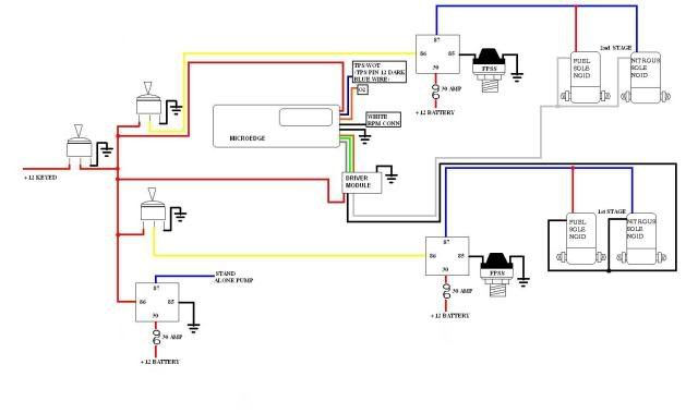
Here is a schematic that I draw, im thinking on use one general swtich to turn on all, and besides one indivual switch for each one of the stages. To provide the fuel for both stages Ill be using a "y" fitting, with these I have one doubt on the wiring, its ok to run only 1 fpss for 2 stages(first draw) before the fitting or I nead one fpss for each stage(second draw) after the y fitting.
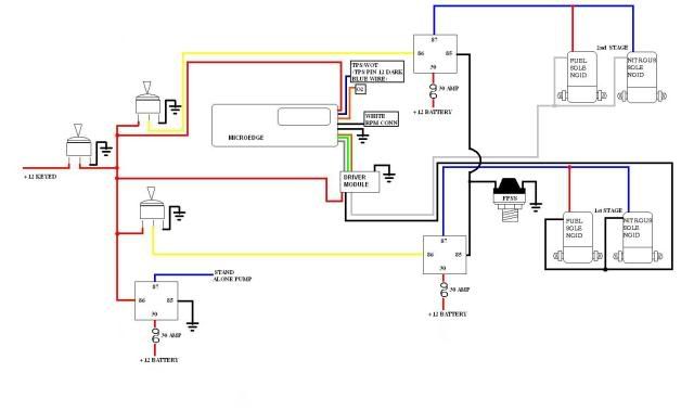
If I go only with one before the "y" and one stage is running when the second stage goes in, it wont shut down all of the system because of the pressure being dropping by the demand of fuel , or can be corrected with a good regulator.
Im thinking on use one stage of 150 hps on the progressive, and the second will be 100 with some timing delay.
Here is a schematic that I draw, im thinking on use one general swtich to turn on all, and besides one indivual switch for each one of the stages. To provide the fuel for both stages Ill be using a "y" fitting, with these I have one doubt on the wiring, its ok to run only 1 fpss for 2 stages(first draw) before the fitting or I nead one fpss for each stage(second draw) after the y fitting.
If I go only with one before the "y" and one stage is running when the second stage goes in, it wont shut down all of the system because of the pressure being dropping by the demand of fuel , or can be corrected with a good regulator.
Im thinking on use one stage of 150 hps on the progressive, and the second will be 100 with some timing delay.
 01-05-2010, 09:38 AM
#2
FormerVendor
iTrader: (4)
Join Date: Jul 2005
Location: Glenolden, PA
Posts: 1,954
Likes: 0
Received 0 Likes
on
0 Posts
Some of the colors are off on the diagram, I don't know if thats because they weren't showing up well or not...
One thing for sure get the 12+ switched on the microedge off of the main arming switch. You'll want this hard wired to kick on every time the key is tripped.
I'd personally run the fpss as close to the solenoid as possible to monitor pressure drop where it counts the most. If that means you need 2 of them then go with diagram 2. I personally wouldn't run them but I've never been a huge fan of them.
Nick
01-07-2010, 01:33 AM
#3
Teching In
Thread Starter
Join Date: Aug 2007
Posts: 19
Likes: 0
Received 0 Likes
on
0 Posts
Some of the colors are off on the diagram, I don't know if thats because they weren't showing up well or not...
One thing for sure get the 12+ switched on the microedge off of the main arming switch. You'll want this hard wired to kick on every time the key is tripped.
I'd personally run the fpss as close to the solenoid as possible to monitor pressure drop where it counts the most. If that means you need 2 of them then go with diagram 2. I personally wouldn't run them but I've never been a huge fan of them.
Nick
One thing for sure get the 12+ switched on the microedge off of the main arming switch. You'll want this hard wired to kick on every time the key is tripped.
I'd personally run the fpss as close to the solenoid as possible to monitor pressure drop where it counts the most. If that means you need 2 of them then go with diagram 2. I personally wouldn't run them but I've never been a huge fan of them.
Nick
ok Im taking out an making there own switch for the microedge and the driver module.
The leanout function on the microedge can act like some kind of a replacement for the fspp? as soon it get lean will turn off the system(after all gets thrashed lol).
Continuing whit installation, so far Im just hooked some wires for the microedge: power, ground, tps voltage and rpm, maybe tomorrow Ill do the o2 sensor narrowband(expecting on get a wideband later).
Can somebody explain me why on the microedge the readings of the rpm are like 250 lower than the tach in the board?, I take the signal from the white wire on pin 35, which one it more accurate?
My tps voltage on idle its 0.59 is this ok?
01-07-2010, 09:38 AM
#4
FormerVendor
iTrader: (4)
Join Date: Jul 2005
Location: Glenolden, PA
Posts: 1,954
Likes: 0
Received 0 Likes
on
0 Posts
the quality of the image went off crappy on the process of hosting, the only wire that I didnt draw its the pink one, because at this moment I dont think on using a purge, so whats the best thing to do whit that wire, isolate it and leave it loose, wire up to a graund or to a hot wire?
Nick
01-08-2010, 01:03 AM
#5
Teching In
Thread Starter
Join Date: Aug 2007
Posts: 19
Likes: 0
Received 0 Likes
on
0 Posts
I set it like the manual says on the 1-8 p/rev when connecting to a tach out signal on the lsx, and on number 2 its where the rpm reading gets closer to the cluster, if I go up on the p/rev option the rpm displayed get lower, and if I set it on 1 the value goes very high, on 2 Im good?
Also I already have done the O2 sensor, narrowband, but went kind off wrong I guess, because when I turn on the engine displays a value and it remains ok but a soon the engine starts to get warm the value begins to jumping and for some moments reads 0 the voltage, this maybe can be product of a bad connection?, or this is normal on the narrowband.
I got a set of jet hot headers with the 4 wires o2, Im conected on the extension on the purple wire.
01-08-2010, 09:28 AM
#6
FormerVendor
iTrader: (4)
Join Date: Jul 2005
Location: Glenolden, PA
Posts: 1,954
Likes: 0
Received 0 Likes
on
0 Posts
I set it like the manual says on the 1-8 p/rev when connecting to a tach out signal on the lsx, and on number 2 its where the rpm reading gets closer to the cluster, if I go up on the p/rev option the rpm displayed get lower, and if I set it on 1 the value goes very high, on 2 Im good?
Also I already have done the O2 sensor, narrowband, but went kind off wrong I guess, because when I turn on the engine displays a value and it remains ok but a soon the engine starts to get warm the value begins to jumping and for some moments reads 0 the voltage, this maybe can be product of a bad connection?, or this is normal on the narrowband.
I got a set of jet hot headers with the 4 wires o2, Im conected on the extension on the purple wire.
That is normal on a narrowband sensor.
Nick
01-09-2010, 01:33 AM
#7
Teching In
Thread Starter
Join Date: Aug 2007
Posts: 19
Likes: 0
Received 0 Likes
on
0 Posts
Thanks Nick for taking the time to solve my doubts jeje, but I hope not to bother whit so many questions, cause I think there are more to come as continue the installation of the whole system 
Another question that I have is about the jetting on your kits, one of the stage is a brand new nozzle kit that I got whit the microedge on your blackfriday sale, and the other one is a tnt that a friend sold me pretty cheap. And Im thinking on make my own stand alone whit some parts that I have laying around. I have a black holley pump that is rated at 140 gph and 14psi, this pump is good for the dedicated?
What jets will you suggest usin 14 psi for a 100 hps and for 150?
Trending Topics
01-11-2010, 10:35 AM
#8
FormerVendor
iTrader: (4)
Join Date: Jul 2005
Location: Glenolden, PA
Posts: 1,954
Likes: 0
Received 0 Likes
on
0 Posts
Thanks Nick for taking the time to solve my doubts jeje, but I hope not to bother whit so many questions, cause I think there are more to come as continue the installation of the whole system
Another question that I have is about the jetting on your kits, one of the stage is a brand new nozzle kit that I got whit the microedge on your blackfriday sale, and the other one is a tnt that a friend sold me pretty cheap. And Im thinking on make my own stand alone whit some parts that I have laying around. I have a black holley pump that is rated at 140 gph and 14psi, this pump is good for the dedicated?
What jets will you suggest usin 14 psi for a 100 hps and for 150?
Shoot me a PM and we can discuss further.
Nick
01-22-2010, 04:32 PM
#10
Teching In
Thread Starter
Join Date: Aug 2007
Posts: 19
Likes: 0
Received 0 Likes
on
0 Posts
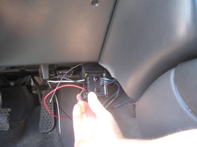
Continuing with all the wiring now with the driver module, this needs go as close as I can to the solenoids or I can make some extension for the wires and let it inside, I was thinking on putting it next to the ALDL here an image of where I want to mount it