Rodent problem...
 03-20-2010, 06:40 AM
#1
Registered User
Thread Starter

Join Date: Mar 2010
Location: Indianapolis
Posts: 11
Likes: 0
Received 0 Likes
on
0 Posts
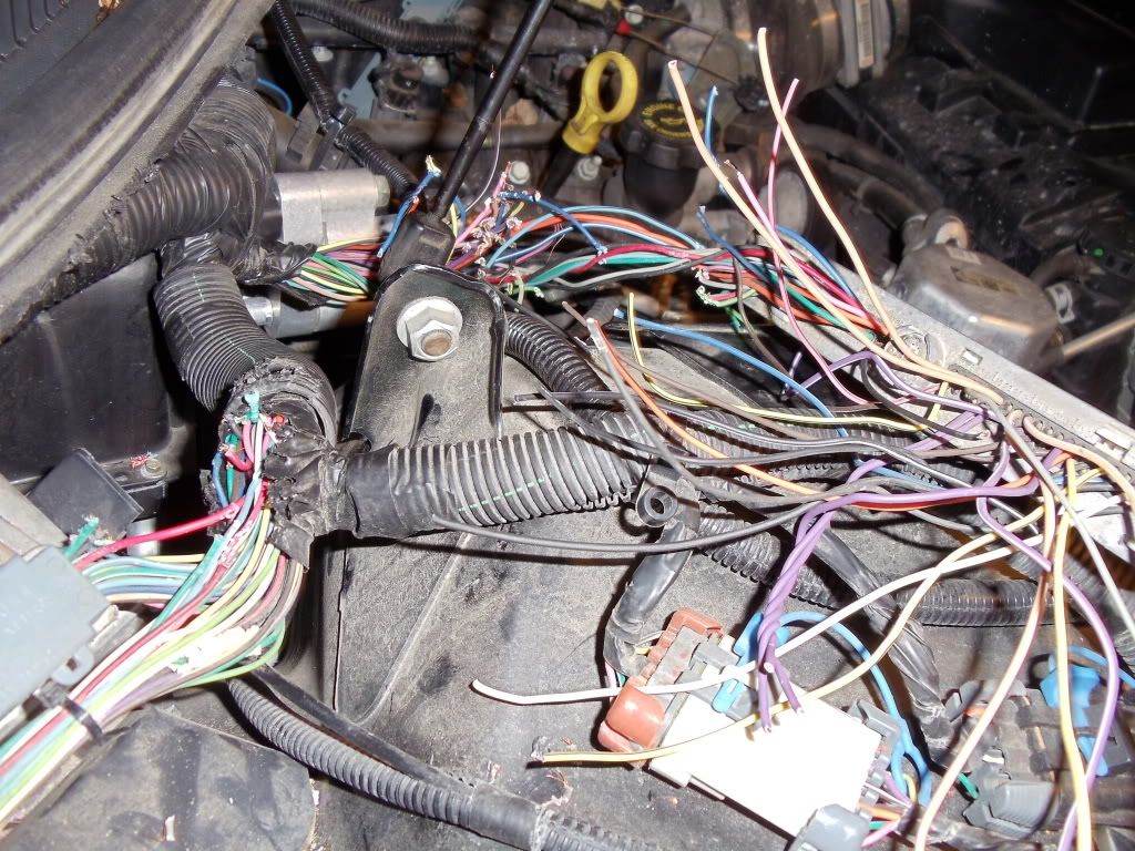
Rat, Squirrel, or Chipmunk ate through every one of the wires by the PCM. Luckily the Red connector wires were only eaten to where I could find the proper color matches. Unfortunately the Blue connector has too many wires of the same color. Trying to narrow it down, I am down to the HO2 sensors and fuel injector pins. I was able to find the pins here, but not sure where bank 1 and 2 sensors are. I can eliminate the wires by tracing the injector placement, but not sure where the Bank 1 sensors 1&2 are, and where bank 2 sensors 1&2 are. Does anyone have a picture I can locate where this is? Mostly trying to eliminate pruple and tan wires now. I am hoping I can use an ohmmeter and trace the similar colored wires and fix this damn thing! Warning, I have no idea what I am doing but trying like hell! Any attempted help would be greatly appreciated!

 03-20-2010, 04:34 PM
#5
Registered User
Thread Starter
Join Date: Mar 2010
Location: Indianapolis
Posts: 11
Likes: 0
Received 0 Likes
on
0 Posts
Here..this might help ya..peel back the wires to see the color..
http://www.lt1swap.com/2001_PCM_CONN_PINOUT.htm
http://www.lt1swap.com/2001_PCM_CONN_PINOUT.htm
Wires not connected on blue with similar colors...
3,61 (PNK/BLK)
46,48(GRA)
25,26 (TAN)
28,29(TAN/WHT)
33,65,66(PPL)
68,69(PPL/WHT)
21,37(YEL/BLK)
17,51(BLU)
36,60,80(BLK)
I'm thinking I should be able to trace injector numbers and eliminate other similar colors with process of elimination. But locating the "bank 1, sensor 1&2" and "bank 2, sensor 1&2", I don't know where they are. I'm hoping I can splice in and figure out the wires by using an ohmmeter, but I need to know where the bank sensors are. I can't find out where they are, been googling with no luck. As much as I can make sense, the bank 1 is the left side of the motor, and bank two is on the right side...? Are they hooked in to one of the coils on each side? If so, which coil!
03-20-2010, 04:53 PM
#7
Registered User
Thread Starter
Join Date: Mar 2010
Location: Indianapolis
Posts: 11
Likes: 0
Received 0 Likes
on
0 Posts
Also...when it says Bank one sensor 1 for the high signal HO2 sensor, is that located on one of the coils, or elsewhere?
Need to locate...
HO2 high signal bank 1 sensor 1
HO2 high signal bank 1 sensor 2
HO2 high signal bank 2 sensor 1
HO2 high signal bank 2 sensor 2
HO2 low signal bank 1 sensor 1
HO2 low signal bank 1 sensor 2
HO2 low signal bank 2 sensor 1
HO2 low signal bank 2 sensor 2
I'm thinking it is either two plugs with 4 inputs, or 4 plugs with two inputs, just need to know where this would be. I appreciate your help.
Trending Topics
03-27-2010, 01:26 AM
#9
Registered User
Thread Starter
Join Date: Mar 2010
Location: Indianapolis
Posts: 11
Likes: 0
Received 0 Likes
on
0 Posts
I was able to eliminate the o2 sensors! Thanks for your help on where to find them.
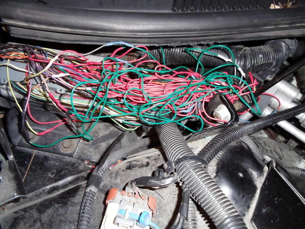
Coming along...here is what I have left to connect.
Dark blue pin 51 (knock sensor 1), behind the intake? I don't see me getting behind the intake to see it. The other dark blue is Pin 17(Transmission fluid pressure switch signal B) If I knew where the transmission pressure switch was for sure, I would easily be able to eliminate disconnecting and getting to the knock sensor.
Gray 48 (MAP sensor), again behind the intake? Gray 46 (fuel tank pressure sensor), where is this?. Gray 23 (low reference), wtf?
60,80 Black(low reference) No clue how I could possibly eliminate these two. I have a Predator tuner, if I start touching these wires (assuming it will start now), will I damage anything other than maybe popping a fuse? I'm wondering if my tuner will show the codes saying the sensors are bad, then codes disappear if I connect the proper wire? Hoping I can finish this way...?
03-27-2010, 04:48 AM
#10
Registered User
Thread Starter
Join Date: Mar 2010
Location: Indianapolis
Posts: 11
Likes: 0
Received 0 Likes
on
0 Posts
I figured out the black wires, there were better descriptions on another listings for pins. The one I really want to know now is where the transmission fluid pressure switch signal B is located (pin 17) Please help!!! I'm almost done! 
 03-27-2010, 05:54 PM
#12
Registered User
Thread Starter
Join Date: Mar 2010
Location: Indianapolis
Posts: 11
Likes: 0
Received 0 Likes
on
0 Posts
I went to the fuel tank, I see a connector plug going into the body on the drivers side. I tried running the gray wires, I only got one to read on the ohmmeter from the pcm, but it was to a gray/black wire in the connector instead of all gray. Anyone know where I can find the related wire numbers for this connector? I have three solid gray wires, two of them go to the fuel tank
Last edited by Treefifty; 03-27-2010 at 05:55 PM. Reason: clarity
04-02-2010, 11:48 PM
#13
Registered User
Thread Starter
Join Date: Mar 2010
Location: Indianapolis
Posts: 11
Likes: 0
Received 0 Likes
on
0 Posts
Update...
Car runs now, but when I give it wot around 20-30, it doesn't kick down. Same thing from 60-70. The AT does not down shift ever. I thought it might be wires mixed up for the TP sensor, but I cut and retraced them to the PCM...it is only giving me one code on my scanner, p1635. Anyone have ideas what exactly this code is telling me and if it has anything to do with the transmission not downshifting?
Car runs now, but when I give it wot around 20-30, it doesn't kick down. Same thing from 60-70. The AT does not down shift ever. I thought it might be wires mixed up for the TP sensor, but I cut and retraced them to the PCM...it is only giving me one code on my scanner, p1635. Anyone have ideas what exactly this code is telling me and if it has anything to do with the transmission not downshifting
04-03-2010, 12:32 AM
#14
Registered User
Thread Starter
Join Date: Mar 2010
Location: Indianapolis
Posts: 11
Likes: 0
Received 0 Likes
on
0 Posts
Ok, this is very strange....
I was down to three gray wires on blue connector (48,46,23) Out of instinct I decided to cut the soldered wire on 48 to see if there would be a MAP sensor code come on just in case I got it mixed up with another gray wire....now it downshifts and I noticed my gas gage isn't pegged past full and working properly....and the code disappeared and it's acting like nothing is wrong.
I DARE you guys explain why this is happening! Lol. Should I leave 48 wire disconnected? Will anything happen down the road if I do, or should I expect sluggish behavior down the road? It's running tip top
04-04-2010, 05:46 AM
#15
Registered User
Thread Starter
Join Date: Mar 2010
Location: Indianapolis
Posts: 11
Likes: 0
Received 0 Likes
on
0 Posts
SUCCESS!!!! Apparently the MAP was running off the fuel 5v line, had the ground connected to a the 5v MAP line, that';s why it was giving me a code and disappeared after I cut it. Had to do some problem solving on paper to figure it out. Funny the last three wires gave me the most trouble. I was able to figure out the two blue wires because luckily they were .010 difference in diameter using micrometers and process of elimination. Runs perfect! It's not pretty, but it works....