LC-1 through 02 sensor
 12-20-2010, 06:40 PM
#1

So I played with this for awhile and got frustrated, and just started working on it again. My AFR pegs at 20.9 and doesn't move... Any Ideas what could be wrong? I'm using this as my guide...
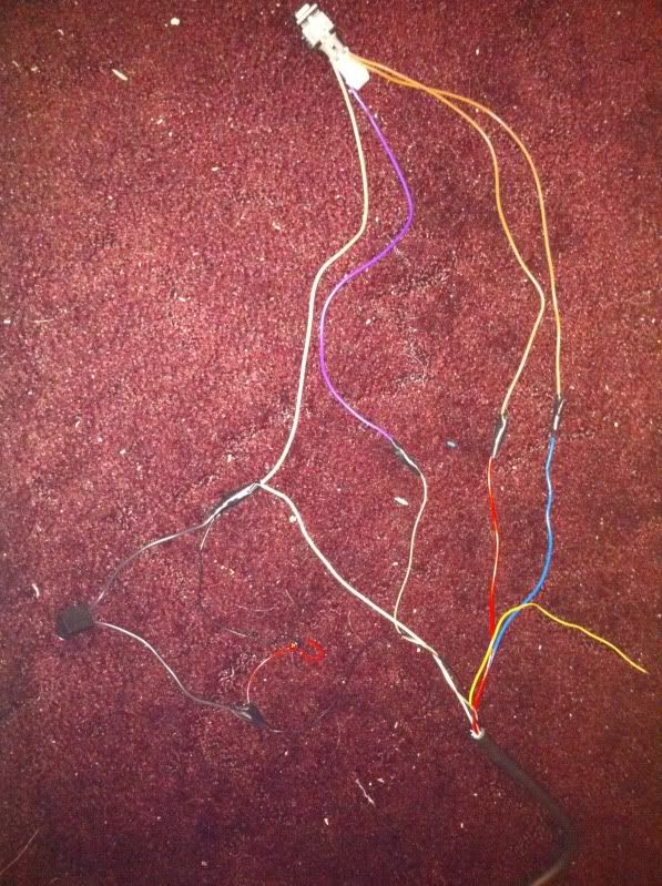
Hard to see but this is my actual wiring. Soldered to the best of my abilities
OK, I just got done wiring my LC-1 to be used connected to the rear o2 sensor. I used the following wiring diagram.

The beauty of this set up is that it is self contained. So I can move it between my 2 Fbodies. All I need to do is put the WB into a welded bung. And connect the harness to the rear o2 sensor connector. Then Log with HP tuners. Note the wiring above is looking at the female end of the connector when you wire the male connector into your LC-1 unit you need to take that into account otherwise you will be flipping A and C, and B and D.
As far as the PID I had to do a bit of extra work. First you need to log the rear o2 sensor voltage. It is under Fuel System>Oxigen Sensors>O2 Voltage B1S2 (SAE) (mV) (if connected to the drivers rear O2)/O2 Voltage B2S2 (SAE) (mV) (if connected to the passenger rear O2). Then you need to create a custom PID. I called mine Rear O2 Voltage (WB), under Abbrv: o2 wb, then leave sensor blank and select afr under units. Now in the Function: this is what I used (([PID.21]/1000)/.125)+10. Note the PID.21 is the rear Driver's side o2 you will want PID.25 for the passenger. Also note that I divided the output of the PID by 1,000. The reason for that is that the pid's output is in mV (millivolts) I need the number in volts so I can compare it with my set range output in the LC-1 (0-1v). .125 is derived for 1v/8. As mentioned in previous posts. So now to the AFR Error. I create another custom PID called AFR Error, under Abbrv: AFR E2, then leave sensor blank and select % under units. Now in the Function: this is what I used 100*(((([PID.21]/1000)/.125)+10)-[SENS.121])/[SENS.121]. As far as explanation for this one notice I use the same formula that I used in my wideband pid then I subtracted [SENS.121] (which is the commanded AFR) then divided it by the commanded AFR and multiplied it by 100 to get the percentage of error.
I did a couple of logs tonight and started tunning my VE tables and this is so much easier that using fueltrims. I got my VE pretty close in 2 runs. I need to do another run to verify. But it looking good so far. I'll post a picture later of the harness I made for reference purposes.
Enjoy!
Hard to see but this is my actual wiring. Soldered to the best of my abilities