
Foxbody and PSI Conversion guys
 04-09-2012, 12:36 PM
#1
Staging Lane
Thread Starter
iTrader: (1)

Join Date: Sep 2011
Location: Cleveland
Posts: 60
Likes: 0
Received 0 Likes
on
0 Posts
Car is getting close just gotta get the wiring down. A few questions for you.
The brown wire for ignition relay on the harness should go where? I was thinking of just using the 12v power wire that would normally run the mustang ecu but it is a 12ga wire and the brown wire to the relay is only 18ga. Where should I tie it into?
Also for the gauge cluster, simple enough to run speedo and tach wires to it from the harness, but what about power to the gauge, I know the grounds and have the pin outs. It is a 98 gauge cluster.
Lastly is the alternator, it is a gto drop out and has the two wire alternator. I know white traces back to the battery and brown usually goes to gauge, but can just wire a 470 ohm resistor in there, could I also run this just to the ignition power. But again its 12ga to 18ga. What do I do!?
 04-09-2012, 03:22 PM
#2
TECH Apprentice
iTrader: (12)
Join Date: Oct 2011
Location: Denton Md
Posts: 381
Likes: 0
Received 0 Likes
on
0 Posts
Car is getting close just gotta get the wiring down. A few questions for you.
The brown wire for ignition relay on the harness should go where? I was thinking of just using the 12v power wire that would normally run the mustang ecu but it is a 12ga wire and the brown wire to the relay is only 18ga. Where should I tie it into?
Also for the gauge cluster, simple enough to run speedo and tach wires to it from the harness, but what about power to the gauge, I know the grounds and have the pin outs. It is a 98 gauge cluster.
Lastly is the alternator, it is a gto drop out and has the two wire alternator. I know white traces back to the battery and brown usually goes to gauge, but can just wire a 470 ohm resistor in there, could I also run this just to the ignition power. But again its 12ga to 18ga. What do I do!?
The brown wire for ignition relay on the harness should go where? I was thinking of just using the 12v power wire that would normally run the mustang ecu but it is a 12ga wire and the brown wire to the relay is only 18ga. Where should I tie it into?
Also for the gauge cluster, simple enough to run speedo and tach wires to it from the harness, but what about power to the gauge, I know the grounds and have the pin outs. It is a 98 gauge cluster.
Lastly is the alternator, it is a gto drop out and has the two wire alternator. I know white traces back to the battery and brown usually goes to gauge, but can just wire a 470 ohm resistor in there, could I also run this just to the ignition power. But again its 12ga to 18ga. What do I do!?
04-09-2012, 04:01 PM
#3
Staging Lane
Thread Starter
iTrader: (1)
Join Date: Sep 2011
Location: Cleveland
Posts: 60
Likes: 0
Received 0 Likes
on
0 Posts
Alright thanks lol, the one wire I was looking into running it off of used to power the ford ecu, so I am guessing that should have power while cranking, its off of the ignition switch. Just don't like the different size wire.
04-09-2012, 10:10 PM
#4
TECH Regular
iTrader: (5)

Join Date: Feb 2010
Location: Celina, Texas
Posts: 456
Likes: 0
Received 0 Likes
on
0 Posts

If the wire gauge size is larger on the Mustang, it's ok to connect it to the PSI harness. Just put the appropriate size fuse recommended for the relay. just don't use a smaller size wire than on the new harness.
04-10-2012, 06:47 AM
#5
DoWant,
Zipster is correct.
Regarding the gage pinout. If you need the pinout for an F-Body Gage cluster let me know and we can email it. Actually, we should probably make it downloadable on our site. Either way let us know.
Jon
PSI
Zipster is correct.
Regarding the gage pinout. If you need the pinout for an F-Body Gage cluster let me know and we can email it. Actually, we should probably make it downloadable on our site. Either way let us know.
Jon
PSI
__________________

Your Source for LSX Conversion Parts!
www.psiconversion.com
Ebay Store
Facebook/psiconversion
Instagram/psiconversion
'Dont Let EFI Pass You By!'
Your Source for LSX Conversion Parts!
www.psiconversion.com
Ebay Store
Facebook/psiconversion
Instagram/psiconversion
'Dont Let EFI Pass You By!'
04-10-2012, 07:55 AM
#6

The brown wire needs to go to the white/pink wire on the mustang ignition switch. If your not running the neutral safety switch or clutch interlock sw. If you are running the factory NSS or CIS then connect it to the I think red/lt grn or red/lt gray wire. It's the wire that leaves the safety switches and activates the factory starter relay.


Trending Topics
04-10-2012, 10:28 AM
#8
Staging Lane
Thread Starter
iTrader: (1)
Join Date: Sep 2011
Location: Cleveland
Posts: 60
Likes: 0
Received 0 Likes
on
0 Posts
The brown wire needs to go to the white/pink wire on the mustang ignition switch. If your not running the neutral safety switch or clutch interlock sw. If you are running the factory NSS or CIS then connect it to the I think red/lt grn or red/lt gray wire. It's the wire that leaves the safety switches and activates the factory starter relay.
Or should I run brown wire from harness to white/pink and use a 12g wire to go to the small terminal on starter?
04-10-2012, 12:11 PM
#9
So here is how you should have it then:
White/pnk wire from ign sw. This wire will need to be soldered onto brown wire in the PSI harness. The whatever color PSI uses for the starter solenoid control which I would think would be purple. But it should be on pin 87A or 87.
Pins
86 ground
85 Brown wire to white/pink wire
30 12V power, (this is fused already from PSI)
87A this wire will go to the small terminal on the starter.
The starter solenoid does not draw many amps. It's the large terminal on the starter that connects directly to the battery that pulls all the amps.
Also the white/pink wire should be 18ga.
04-10-2012, 08:23 PM
#10
Staging Lane
Thread Starter
iTrader: (1)
Join Date: Sep 2011
Location: Cleveland
Posts: 60
Likes: 0
Received 0 Likes
on
0 Posts
So here is how you should have it then:
White/pnk wire from ign sw. This wire will need to be soldered onto brown wire in the PSI harness. The whatever color PSI uses for the starter solenoid control which I would think would be purple. But it should be on pin 87A or 87.
Pins
86 ground
85 Brown wire to white/pink wire
30 12V power, (this is fused already from PSI)
87A this wire will go to the small terminal on the starter.
The starter solenoid does not draw many amps. It's the large terminal on the starter that connects directly to the battery that pulls all the amps.
Also the white/pink wire should be 18ga.
White/pnk wire from ign sw. This wire will need to be soldered onto brown wire in the PSI harness. The whatever color PSI uses for the starter solenoid control which I would think would be purple. But it should be on pin 87A or 87.
Pins
86 ground
85 Brown wire to white/pink wire
30 12V power, (this is fused already from PSI)
87A this wire will go to the small terminal on the starter.
The starter solenoid does not draw many amps. It's the large terminal on the starter that connects directly to the battery that pulls all the amps.
Also the white/pink wire should be 18ga.
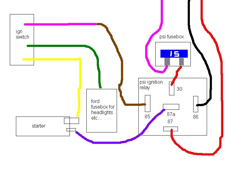
86 has black wire from it already, assuming it will be grounded when ground the ones provided.
85 the brown wire to white/pink as you said
30 goes to the number 4 fuse
87 goes up into harness, not sure where? Pcm?
87a is empty so I run my own wire to the starter solenoid from here?
Then the 12g yellow wire goes straight to the big terminal on starter, as well as the battery, and will power the ford fusebox for lights etc.
There are two wires run down to starter from psi harness as well, says starter(ground) these both go to the big terminal on starter correct?
Sorry I am a noob at wiring.
Like so?
Last edited by DoWantLS1; 04-10-2012 at 08:45 PM.
04-11-2012, 06:12 AM
#11
It looks like the relay is correctly wired in the diagram. The only thing is I don't know why the red wire is coming out of pin 87? I'm assuming it's to power something that they do not want powered during starting. Either way, yes you have it correct.
The yellow wire is what powers up the ignition switch. It should have a fusible link in it where it used to connect to the factory ford solenoid on the fender.
There should not be any other wires needed to run to the starter. Should only be 2 wires: call wire from ign sw, and the large gauge wire from battery. The starter has a ground wire when you buy it that grounds the starter solenoid to the starter motor. Then when you bolt the starter to the block it's grounded that way.
Just an FYI, the rule of thumb is to use the same gauge size wire for grounds that you use on the + battery terminal. This is for main grounds, like block to frame, block to body, body to frame.
04-11-2012, 06:41 AM
#12
Staging Lane
Thread Starter
iTrader: (1)
Join Date: Sep 2011
Location: Cleveland
Posts: 60
Likes: 0
Received 0 Likes
on
0 Posts
Alright sweet thanks for all the help man! And yes the yellow wire has a fuseable link and turns into a few other wires, I just extended it.
As for only 2 wires going to starter then, battery and yellow ign wire, where do the two wires run that come from the harness? Looking at the instructions from psi they are number 26 on their picture and says starter(battery), I assumed that these would also go to the starter?
As for only 2 wires going to starter then, battery and yellow ign wire, where do the two wires run that come from the harness? Looking at the instructions from psi they are number 26 on their picture and says starter(battery), I assumed that these would also go to the starter?
04-11-2012, 07:03 AM
#13
EDIT: looking on their site, it looks like this is the signal wire (26) this wire should go to the small terminal on the starter.
The yellow wire that runs to the starter from factory on the fords, this is just where they borrow power to power up the ign switch. Ford just used the starter as the dist point. But it is not needed for the starting of the car.
The yellow wire that runs to the starter from factory on the fords, this is just where they borrow power to power up the ign switch. Ford just used the starter as the dist point. But it is not needed for the starting of the car.
04-11-2012, 08:18 AM
#14
Staging Lane
Thread Starter
iTrader: (1)
Join Date: Sep 2011
Location: Cleveland
Posts: 60
Likes: 0
Received 0 Likes
on
0 Posts
Oh ok gotcha, wonder why there is two different wires on mine for 26, dont think they would both go to the small terminal, actually I dont even know if they will fit properly, the connector is the size of the big terminal?
04-11-2012, 09:08 AM
#15
Our large wires on for the starter/battery need to have constant power. Remember, your actual 'STARTER' wires must come from the Mustang, not our harness.
Jon
PSI
Jon
PSI
__________________
Your Source for LSX Conversion Parts!
www.psiconversion.com
Ebay Store
Facebook/psiconversion
Instagram/psiconversion
'Dont Let EFI Pass You By!'
Your Source for LSX Conversion Parts!
www.psiconversion.com
Ebay Store
Facebook/psiconversion
Instagram/psiconversion
'Dont Let EFI Pass You By!'
04-11-2012, 09:30 AM
#16
Staging Lane
Thread Starter
iTrader: (1)
Join Date: Sep 2011
Location: Cleveland
Posts: 60
Likes: 0
Received 0 Likes
on
0 Posts
And I guess I should ask what do those 2 wires power?
Last edited by DoWantLS1; 04-12-2012 at 06:05 PM.
 04-12-2012, 08:25 PM
#18
Staging Lane
Thread Starter
iTrader: (1)
Join Date: Sep 2011
Location: Cleveland
Posts: 60
Likes: 0
Received 0 Likes
on
0 Posts
Ok never mind. I figured out the 2 wires from the psi harness to the starter. Which is constant power.
One goes to a fuse in the box supplied by psi, which is for the pcm.
The other goes to the ignition relay. So therefore my drawing should be correct for the starter wiring?
As for alternator wiring, it is out of a gto with a 2 wire plug. Brown and white wires. I plan on just running the gto battery/starter/alter harness in the fox. I know there needs to be a 470 ohm resistor from a power wire to the brown wire on the alternator. So for this, I can connect brown wire to power wire from ignition that is not being used, like the old ecu wire. But this is 12g to 18g. So 12g from ignition switch to fuse(not sure on size here?) then from fuse is the 18g with a 470 ohm resistor in it which goes to alternator. And the white wire ends up going back to the battery.
04-13-2012, 05:14 PM
#20
Please keep notes and take some pics...........I am doing this swap with a PSI harness soon. Any help you can offer/document will be great
The mustang im doing is a 93 so hopefully the wiring will be close to what you are doing.
The mustang im doing is a 93 so hopefully the wiring will be close to what you are doing.