Stroker 383 iron block, AFR heads, FAST top end build thread, lots of pics
 06-21-2012, 07:37 PM
#1
TECH Fanatic
Thread Starter

I realize now that for the amount of $$ spent on this build I could have done a 408 or maybe even more, however the scope and budget of this build has evolved significantly since I started it 1 year ago... It was the power bug, I was totally helpless 
Here are the specs:
LM7 block bored to 3.905", line honed with ARP studs, decked to -0.010" by HKE.
Forged balanced stroker rotating assembly by TSP: Wiseco -3cc pistons, Eagle H-beam rods, K1 4" crankshaft.
Assembled by me with mitutoyo instrumentation.
AFR 210 heads, Pat G camshaft, FAST LSXRT 102mm topend and supporting components, 36lb injectors, 1-3/4" SS LT headers.
Tuning by Pat G in Victoria, TX.
The current planned host vehicle is a 2001 Suburban 2500 4x4. When I have a bigger shop the engine will go in an old muscle car, or whatever I feel like (Grand Wagoneer?).
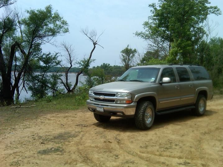
The truck is currently stock, however it has dual 3" exhaust with 2 massive cats, 4l80e tranny, 14-bolt rear end with 4.10 gears, so its a good platform for the high hp engine.
Here are my goals for the engine:
1. Torque
2. Longevity
3. Driveability
4. Good peak power at 6k RPMs
Here is the status of the engine today (21 June):
1. Forged shortblock is assembled and ready.
2. AFR 210 heads and Pat G cam are on order (due in near the end of July)
3. Intake/TB/remaining top end not ordered yet.
Here are the cam specs:
224/228, .566/.571, 115+1 LSA, XE lobes
SCR = 11.3
DCR = 8.5
This is my first engine build so I do not claim to be an expert, I welcome any criticism/suggestions. This is a hobby for me.
Here are the pics!
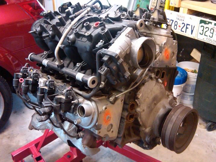
Fresh from LKQ online - $400 engine special!
back from the machine shop
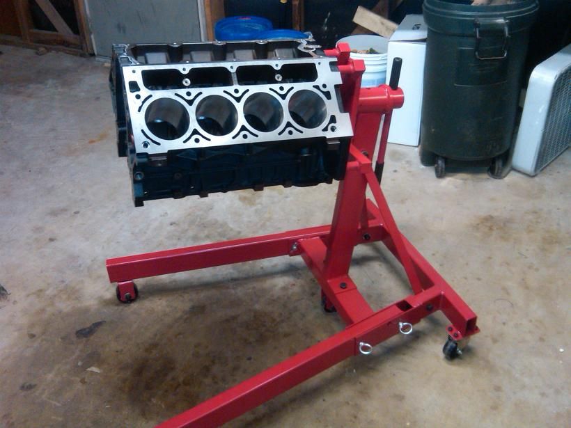
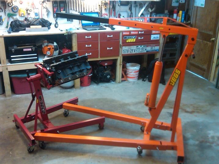
aligning 4-leg engine stand with hoist can be a pain in the ***!
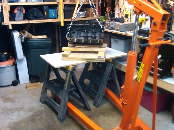
setting block on table for cam bearing install
installing new cam bearings with homemade tool
test fit with OEM camshaft
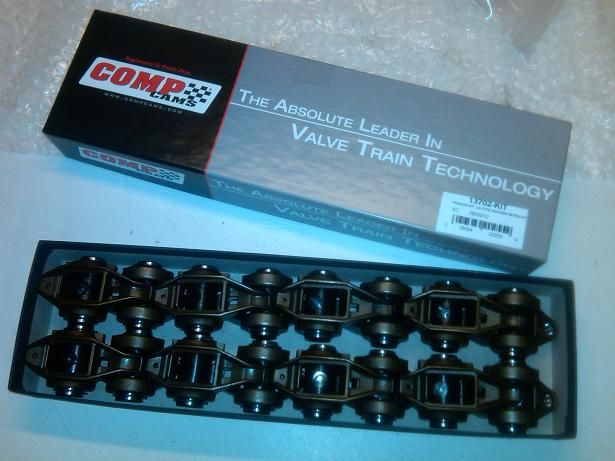
modifying stock rockers for bearing upgrade
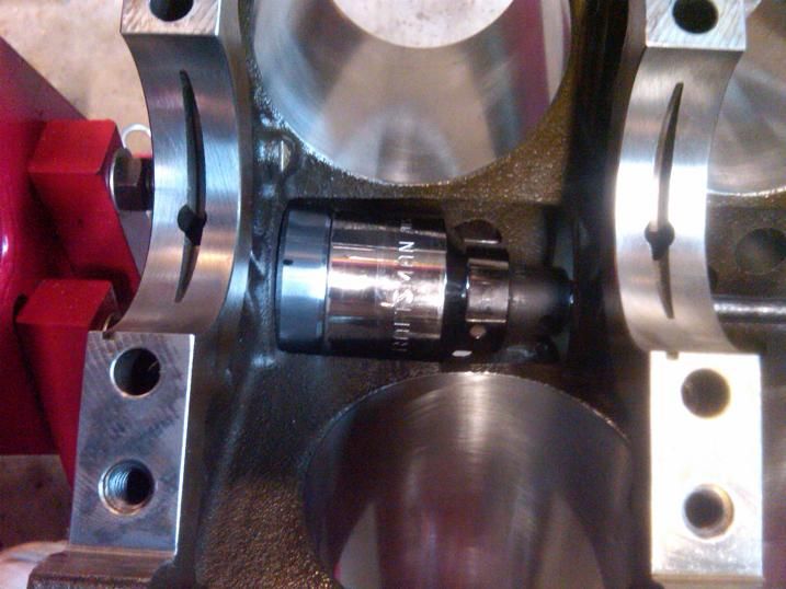
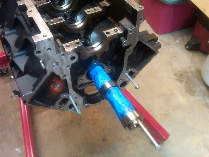
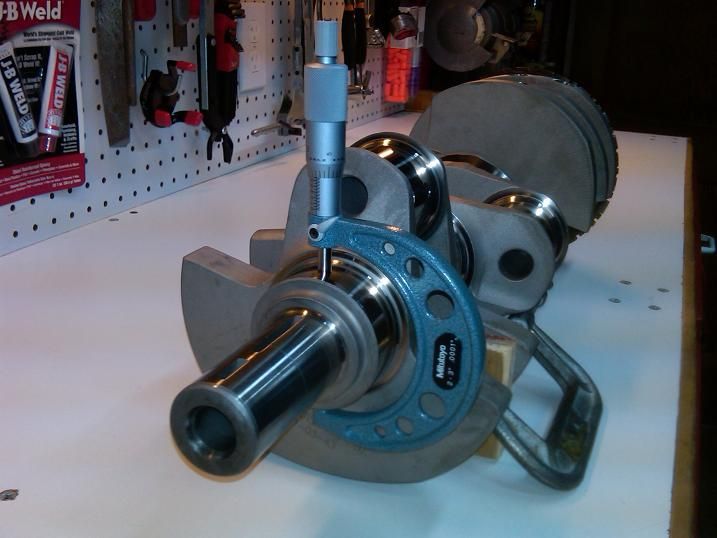
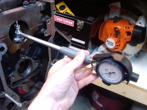
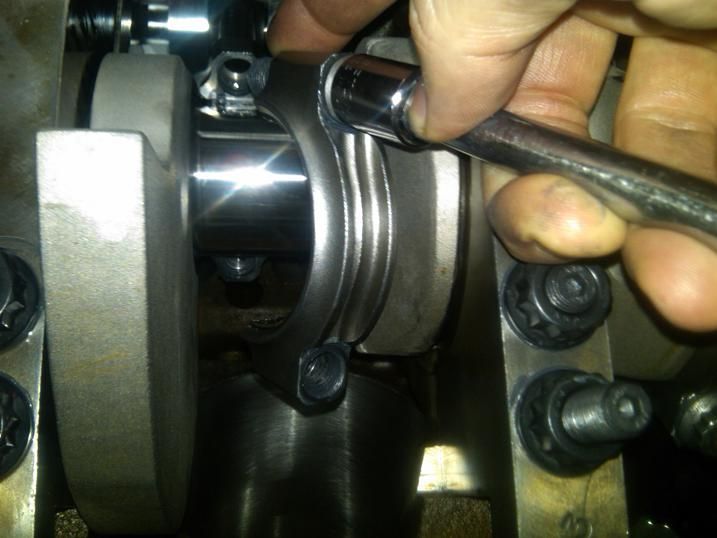
measuring crank journal OD dimensions (as noted, don't do it this way, use the ratchet!)
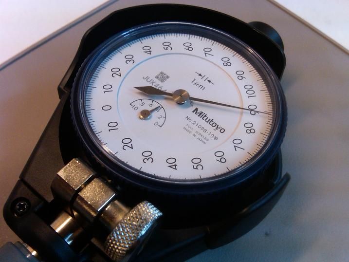
dial bore gauge with 0.001mm resolution
setting up dial bore gauge to crank OD dimensions
measuring main bore ID dimensions
measuring rod bore ID dimensions
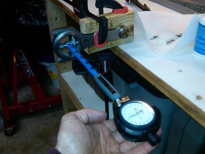
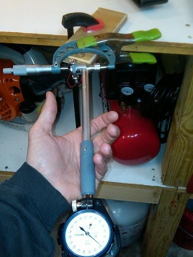
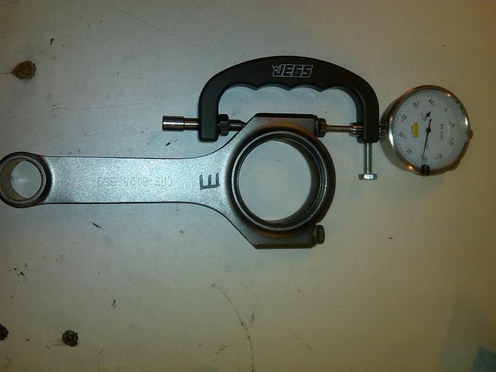
calibrating rod bolt stretch gauge to 2" micrometer standard
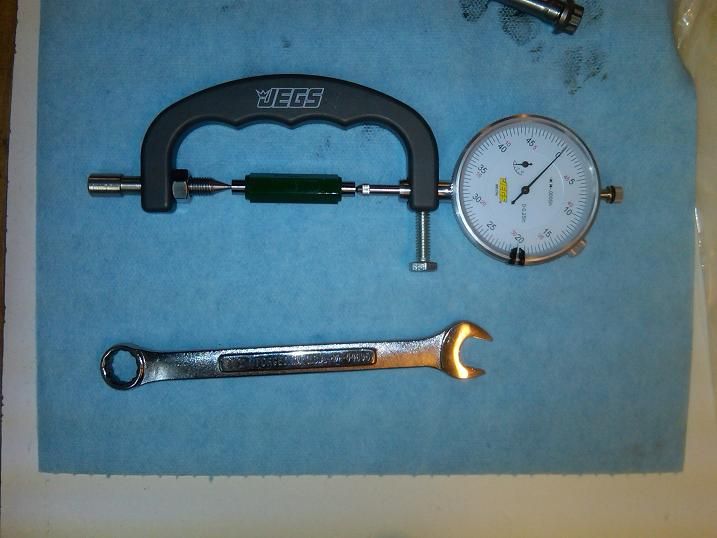
measuring installed stretch of rod bolts (loose rods)
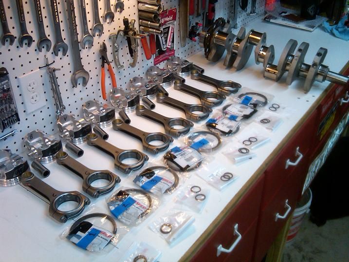
balanced rotating assembly ready for install
studs installed in bare block
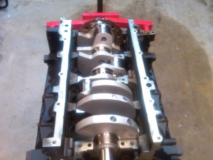
crank set in block
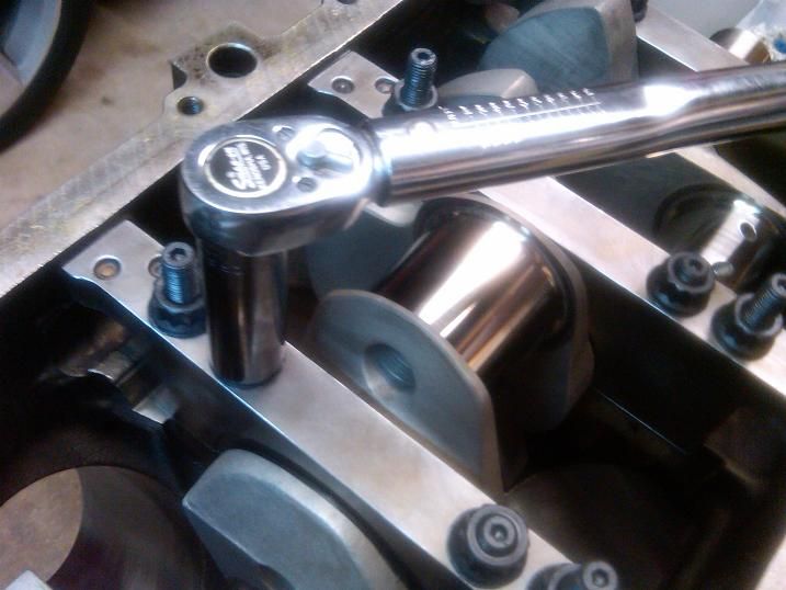
torquing main studs
checking to ensure smooth rotation of crank
installing piston pins
installing piston rings
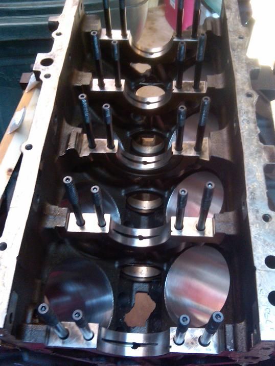
installing pistons/rods to block
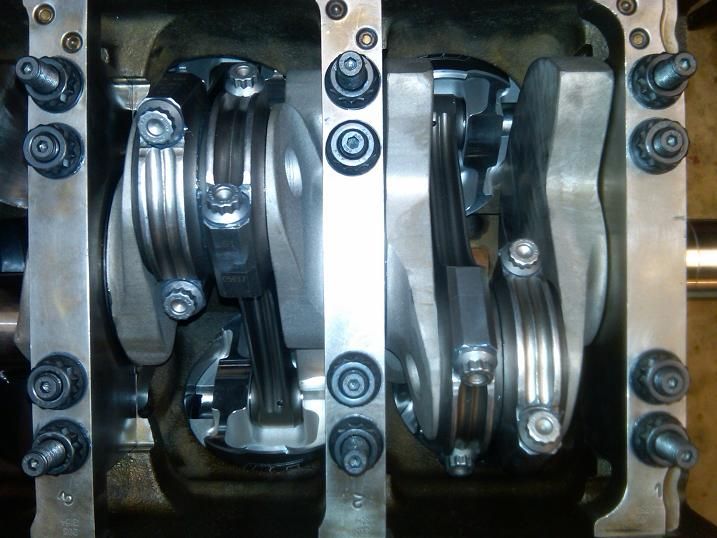
installing rod caps
confirming correct rod bolt stretch after install
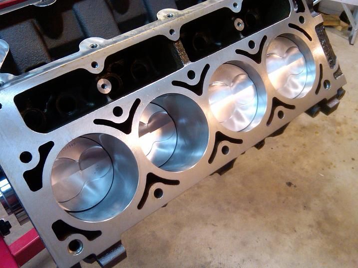
finished shortblock
Thanks for looking, I'll be updating this over the next few months as the build, swap, and tuning come along.

Here are the specs:
LM7 block bored to 3.905", line honed with ARP studs, decked to -0.010" by HKE.
Forged balanced stroker rotating assembly by TSP: Wiseco -3cc pistons, Eagle H-beam rods, K1 4" crankshaft.
Assembled by me with mitutoyo instrumentation.
AFR 210 heads, Pat G camshaft, FAST LSXRT 102mm topend and supporting components, 36lb injectors, 1-3/4" SS LT headers.
Tuning by Pat G in Victoria, TX.
The current planned host vehicle is a 2001 Suburban 2500 4x4. When I have a bigger shop the engine will go in an old muscle car, or whatever I feel like (Grand Wagoneer?).
The truck is currently stock, however it has dual 3" exhaust with 2 massive cats, 4l80e tranny, 14-bolt rear end with 4.10 gears, so its a good platform for the high hp engine.
Here are my goals for the engine:
1. Torque
2. Longevity
3. Driveability
4. Good peak power at 6k RPMs
Here is the status of the engine today (21 June):
1. Forged shortblock is assembled and ready.
2. AFR 210 heads and Pat G cam are on order (due in near the end of July)
3. Intake/TB/remaining top end not ordered yet.
Here are the cam specs:
224/228, .566/.571, 115+1 LSA, XE lobes
SCR = 11.3
DCR = 8.5
This is my first engine build so I do not claim to be an expert, I welcome any criticism/suggestions. This is a hobby for me.
Here are the pics!
Fresh from LKQ online - $400 engine special!
back from the machine shop
aligning 4-leg engine stand with hoist can be a pain in the ***!
setting block on table for cam bearing install
installing new cam bearings with homemade tool
test fit with OEM camshaft
modifying stock rockers for bearing upgrade
measuring crank journal OD dimensions (as noted, don't do it this way, use the ratchet!)
dial bore gauge with 0.001mm resolution
setting up dial bore gauge to crank OD dimensions
measuring main bore ID dimensions
measuring rod bore ID dimensions
calibrating rod bolt stretch gauge to 2" micrometer standard
measuring installed stretch of rod bolts (loose rods)
balanced rotating assembly ready for install
studs installed in bare block
crank set in block
torquing main studs
checking to ensure smooth rotation of crank
installing piston pins
installing piston rings
installing pistons/rods to block
installing rod caps
confirming correct rod bolt stretch after install
finished shortblock
Thanks for looking, I'll be updating this over the next few months as the build, swap, and tuning come along.
Last edited by RezinTexas; 07-14-2012 at 07:04 AM.


Trending Topics
06-27-2012, 12:33 PM
#8
I literally cringed at the picture of the piston rings being installed with needle nose pliers.
The attention to detail is fantastic, but they make a piston ring spreader which would have been a good investment. I think Sears even sells them for about $5.
The attention to detail is fantastic, but they make a piston ring spreader which would have been a good investment. I think Sears even sells them for about $5.
06-27-2012, 02:44 PM
#9
TECH Fanatic
Thread Starter
Thanks for all the replies.
The cylinder walls were coated in oil, and all bearing surfaces with engine assembly lube.
Good point on the pliers on the piston rings. I got the rings 90 percent on by hand, then used the small needle nose pliers for a smooth pull in one direction for the final setting. The force required was quite small. I carefully inspected each ring afterwards to ensure there was no effect.
I just ordered the rest of the valvetrain, and all tooling to check ptv, and degree the cam. More pics to come soon!
 06-30-2012, 09:24 AM
#12
TECH Fanatic
Thread Starter
Got a few more parts in the mail 
- New GM Lifters
- Melling HP Oil Pump, 10295
- Cam Degree and PtV checking tools, etc.
Also should arrive later today:
- Hawk balancer install tool
- Rocker arm bearings
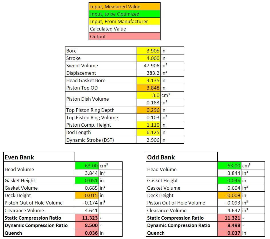
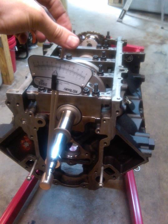
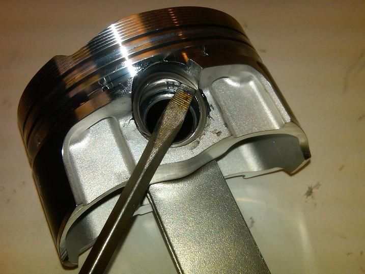
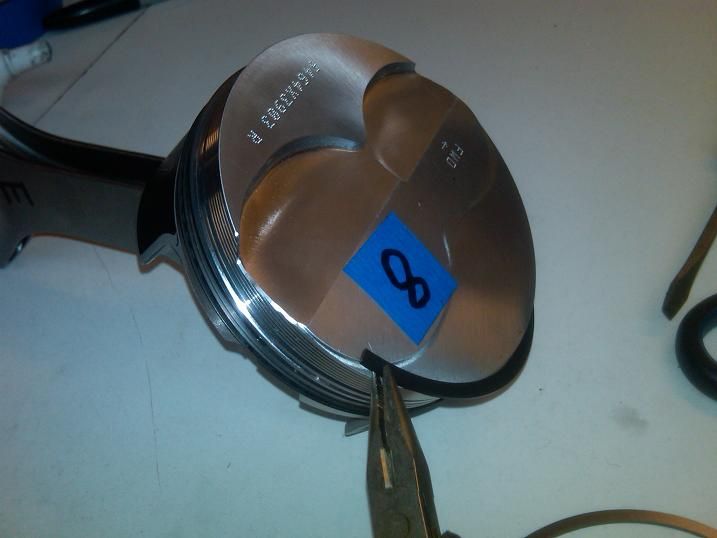
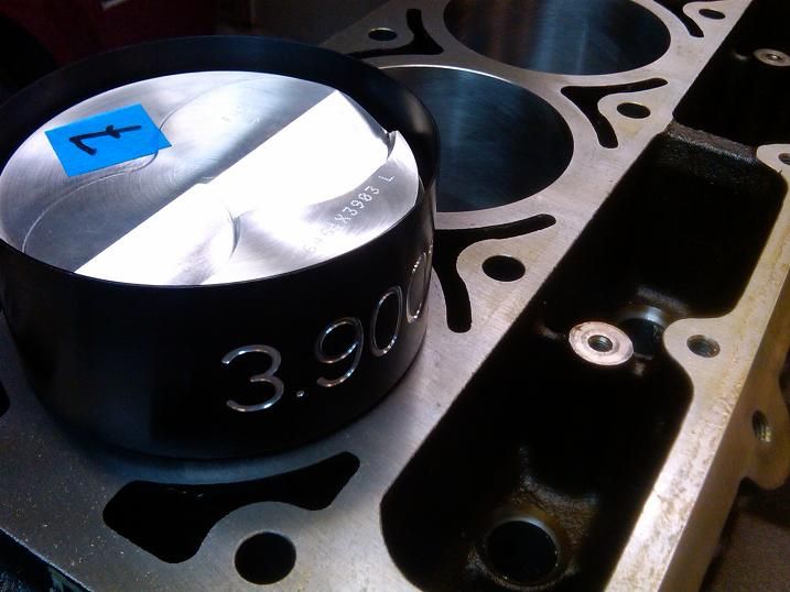
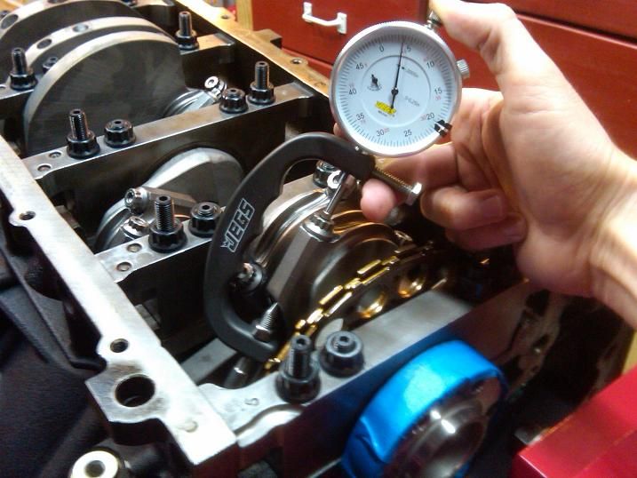
For measuring the deck height, my goal was to measure the height at 3 places on the piston as shown below (both A's are the same elevation).
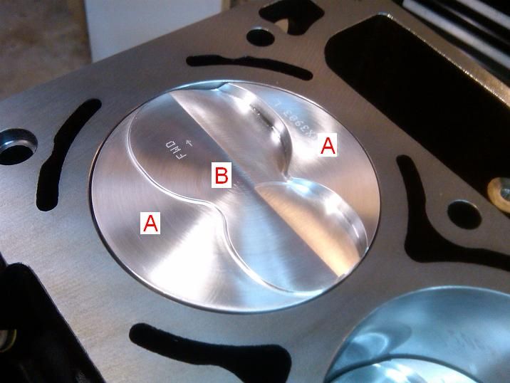
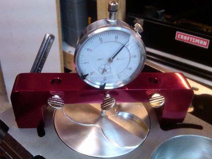
For measurement B, the dial was placed in the geometric center of the piston:
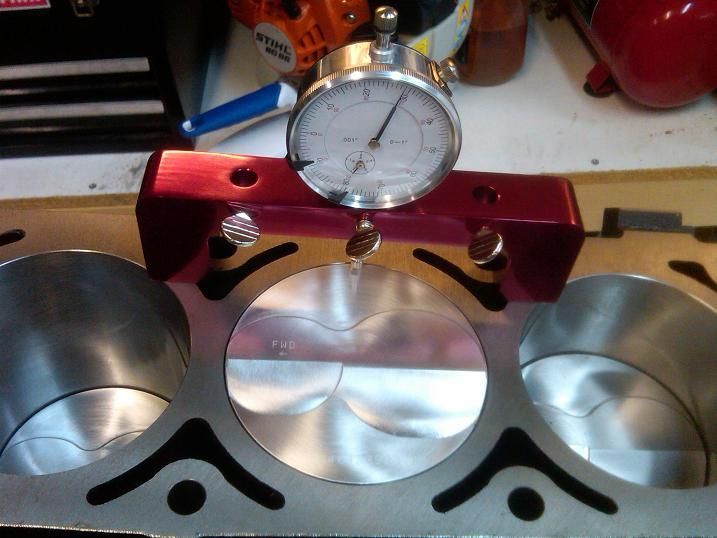
For measurement A, I measured min and max for each side. Min and max were found by rocking the piston by hand. Average values were then calculated.
Here are the results:
Measurement B: Even cylinders were 0.044", Odd cylinders were 0.037". Variance in both cases was 0.000".
Measurement A: Even cylinders averaged 0.015", Odd cylinders averaged 0.008". Variance in both cases was up to 0.004".
Both measurements show that the even cylinders (passenger side bank) all come out of the hole 0.007" more than the other bank.
I'm sure this is not really an issue, but since I'm going full nerd on this build, I might as well try to fix it
If I run a 0.051" head gasket on the even bank, and a 0.045" gasket on the odd bank, I'll equalize the SCR and Quench on both sides...
- New GM Lifters
- Melling HP Oil Pump, 10295
- Cam Degree and PtV checking tools, etc.
Also should arrive later today:
- Hawk balancer install tool
- Rocker arm bearings
For measuring the deck height, my goal was to measure the height at 3 places on the piston as shown below (both A's are the same elevation).
For measurement B, the dial was placed in the geometric center of the piston:
For measurement A, I measured min and max for each side. Min and max were found by rocking the piston by hand. Average values were then calculated.
Here are the results:
Measurement B: Even cylinders were 0.044", Odd cylinders were 0.037". Variance in both cases was 0.000".
Measurement A: Even cylinders averaged 0.015", Odd cylinders averaged 0.008". Variance in both cases was up to 0.004".
Both measurements show that the even cylinders (passenger side bank) all come out of the hole 0.007" more than the other bank.
I'm sure this is not really an issue, but since I'm going full nerd on this build, I might as well try to fix it
If I run a 0.051" head gasket on the even bank, and a 0.045" gasket on the odd bank, I'll equalize the SCR and Quench on both sides...
Last edited by RezinTexas; 06-30-2012 at 10:34 AM.
 06-30-2012, 07:16 PM
#14
TECH Fanatic
Thread Starter
 07-06-2012, 05:36 PM
#16
TECH Fanatic
Thread Starter
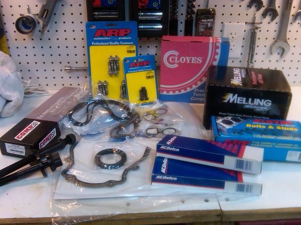
Just ordered a few more parts:
ARP fasteners: head studs, SS header studs, balancer bolt, cam bolts
Cam install gasket kit
Cometic head gaskets
OEM LS2 timing set
Cam from EPS should be in next week
Heads from AFR hopefully in 2-3 weeks...
ARP fasteners: head studs, SS header studs, balancer bolt, cam bolts
Cam install gasket kit
Cometic head gaskets
OEM LS2 timing set
Cam from EPS should be in next week
Heads from AFR hopefully in 2-3 weeks...
07-07-2012, 11:21 AM
#17
TECH Fanatic
Thread Starter
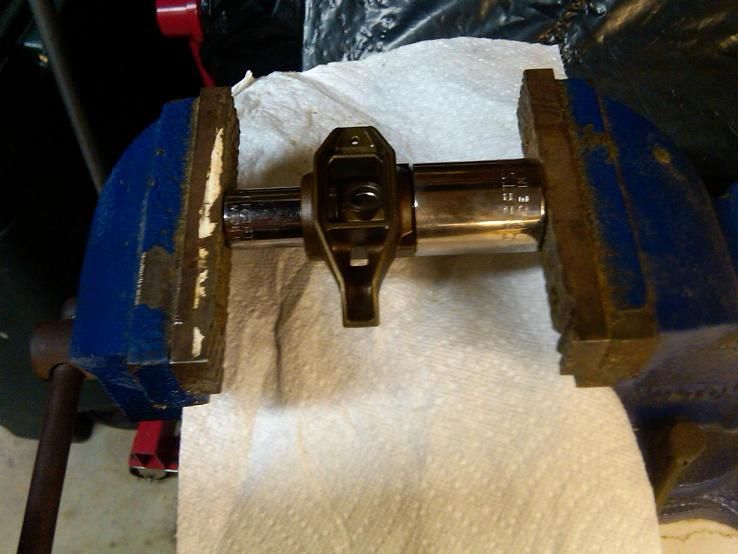
Pressed on the new rocker arm bearings, here is the sequence of pictures.
I do have a vertical hydraulic press, however I found the horizontal screw vice to be quicker.
Parts:
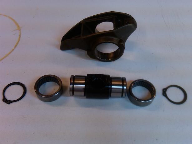
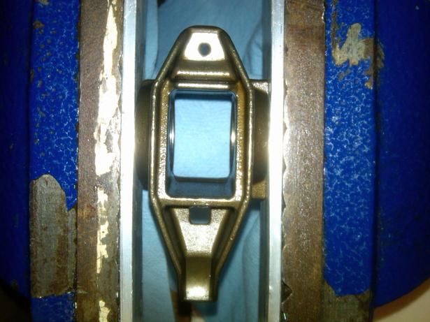
Step 1: Push in first bearing into bare rocker frame
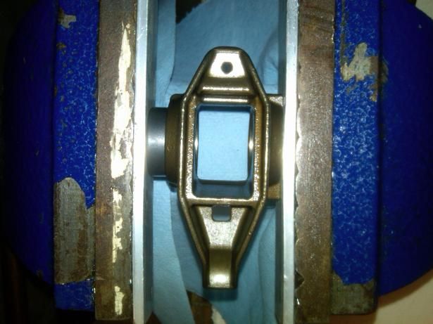
Step 2: Bottom out on rocker frame
Step 3: Insert trunnion (center shaft piece), align 2nd bearing on the right side, add spacer washer (included with kit) on the left side, and press until it bottoms out on trunnion.
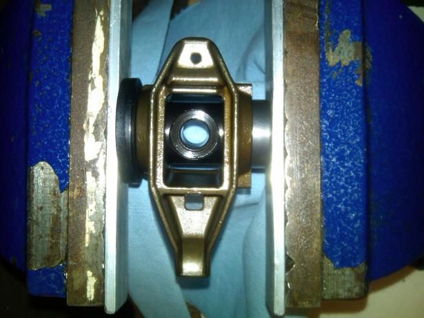
Step 4: Add 2nd spacer washer on right side, centralize trunnion inside each washer. This step is tricky at first to align each washer properly.
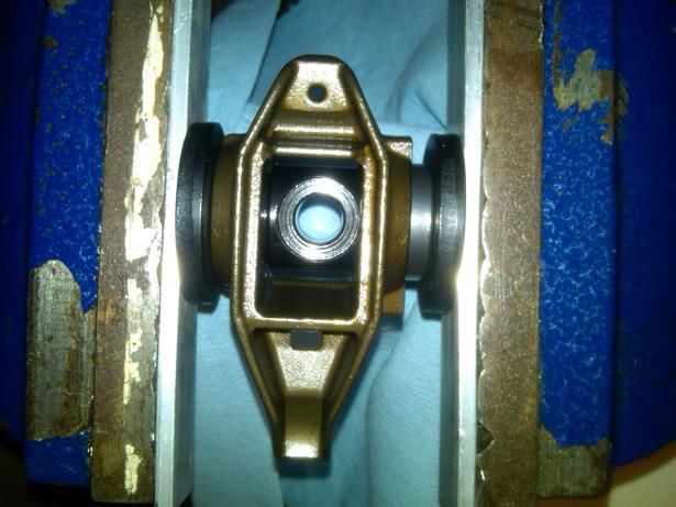
Step 5: Press until it bottoms out on rocker frame.
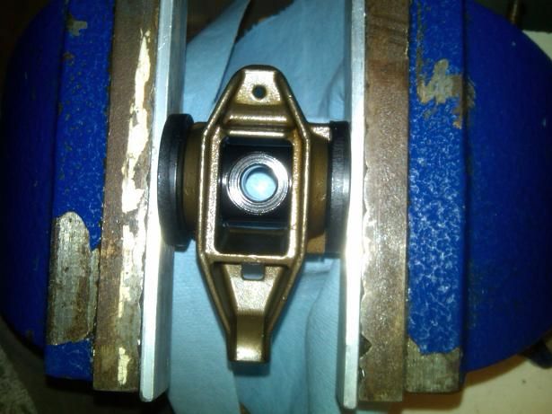
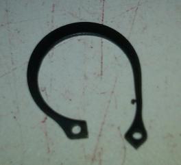
Step 6: Install snap ring.
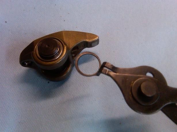
One bent
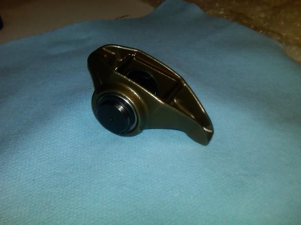
Finished:
I do have a vertical hydraulic press, however I found the horizontal screw vice to be quicker.
Parts:
Step 1: Push in first bearing into bare rocker frame
Step 2: Bottom out on rocker frame
Step 3: Insert trunnion (center shaft piece), align 2nd bearing on the right side, add spacer washer (included with kit) on the left side, and press until it bottoms out on trunnion.
Step 4: Add 2nd spacer washer on right side, centralize trunnion inside each washer. This step is tricky at first to align each washer properly.
Step 5: Press until it bottoms out on rocker frame.
Step 6: Install snap ring.
One bent
Finished:
 07-13-2012, 08:09 PM
#19
TECH Fanatic
Thread Starter
got a few more parts in the mail
Pat G cam from EPS should be here early next week. AFR heads should be here in a week or two.
I have to order 4.135" bore head gaskets (at the recommendation of AFR) even though my engine is 3.905" bore. I'm planning on custom thickness from Cometic.
Pat G cam from EPS should be here early next week. AFR heads should be here in a week or two.
I have to order 4.135" bore head gaskets (at the recommendation of AFR) even though my engine is 3.905" bore. I'm planning on custom thickness from Cometic.