
Microsquirt LSx Walkthrough
 02-18-2013, 12:20 PM
#1
TECH Apprentice
Thread Starter
Join Date: Apr 2011
Posts: 390
Likes: 0
Received 0 Likes
on
0 Posts
I claim no advice from this exercise as all information was obtained through Denmah's article. However, sometime people are more visual learners, or newbys and need a lot of questions answered. I am by no means a savant or serious mechanic, but I do love building hot rods on a budget, and if it wasn't for people like Denmah giving help to the masses, I probably wouldn't have been able to do this.
I am currently working on a fox-chassis 5.3/76mm/th400/8.8/microsquirt setup and have build 90% of my harness and took step by step pictures as WHAT I BELIEVE TO BE CORRECT. I hope Denmah will review this and see any inconsistencies.
Start by just reviewing what all is needed for the Microsquirt:
Required:
Microsquirt
MS harness
Map sensor + pigtail
Coolant Temp + pigtail
Intake air temp + pigtail
Injectors + pigtails x 8
Throttle position sensor + pigtail
Coils + pigtail x2 (bank harness for lsx)
Optional:
02 sensor (recommended)
I ordered all of my supplies from EFI source..
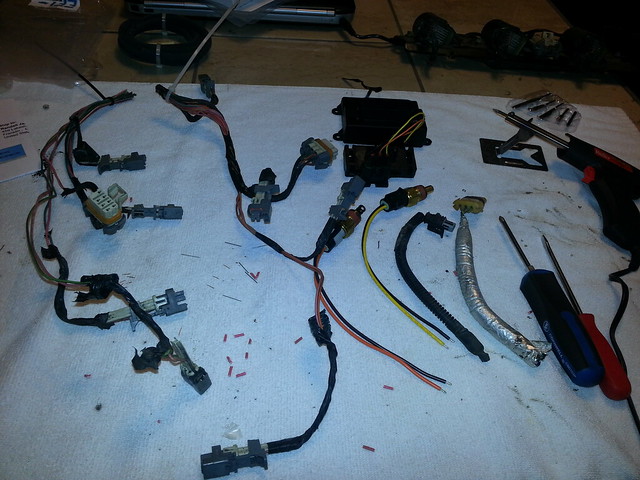
I also clipped off the whole injector/coil harness from each side to give me a rough estimate on length to get going.. looked like this..
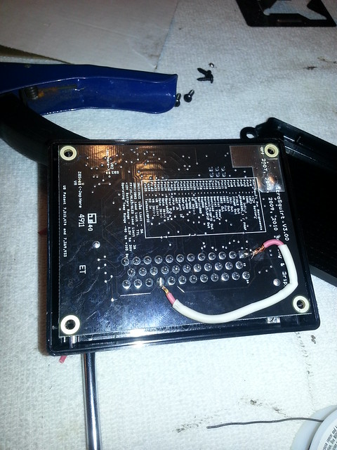
Next, find your Microsquirt computer.. flip it to the backside and find the 4 small screws. Open it up

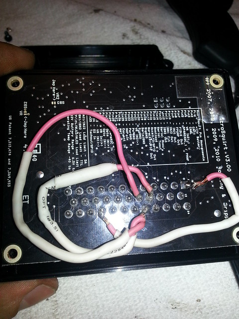
On the back you will see pins for each piece of the MS harness. Start by taking a 1k 1/4watt resistor, and attaching the leads as shown...
Now take 2 4.7k 1/4watt resistors and attach to pins shown..
Note, my pin #1 is soldered like complete ***, ill probably go back and fix it but you get the idea...
Adding these jumpers are for the correct signal for crank sensor and adding two additional circuits for a v8 in wasted spark ignition
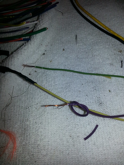
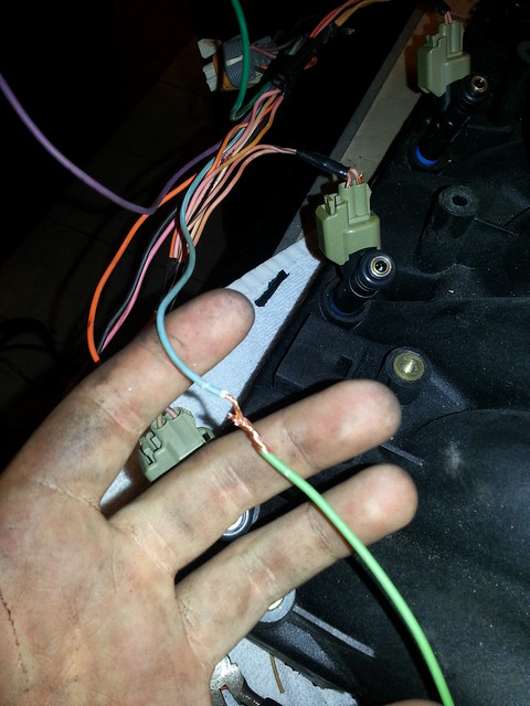
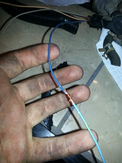
Put the case back together and look for vr1+, this is a shielded wire, but all that is attached is the red wire. This goes to yellow wire on the crank sensor pigtail. (signal)
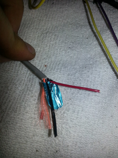
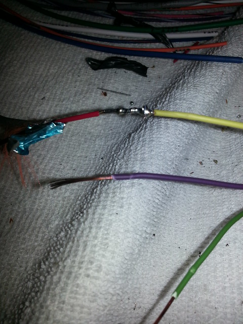
The purple wire (which i indicated by looping) will go to sensor ground (later on in walkthrough)
The last wire, green, will have a 12v source connected to it from fuse box
Crank sensor is done!
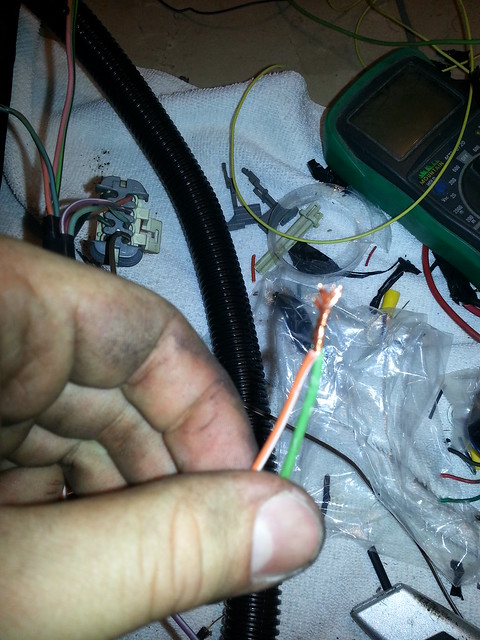
Next find the wires from Microsquirt harness that says INJ1 and INJ2, since this will be a batch fire ignition system, one side is fired, and then the other side.. hence all signals for one side of the engine will be connected to either the green, or the blue respectively.
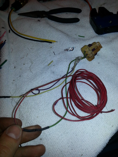
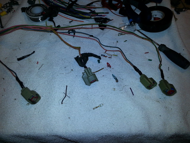
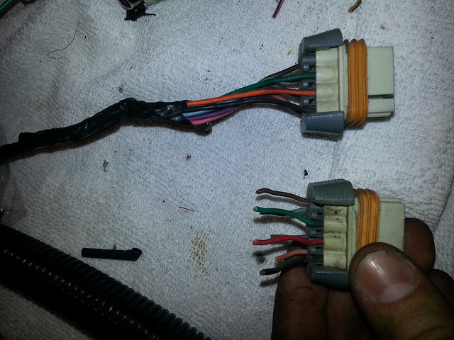
Next, find your injector harness including clips. I cut this off the donor harness as it makes it easier to visualize how long they need to be, and it also helps keep colors somewhat coordinated.
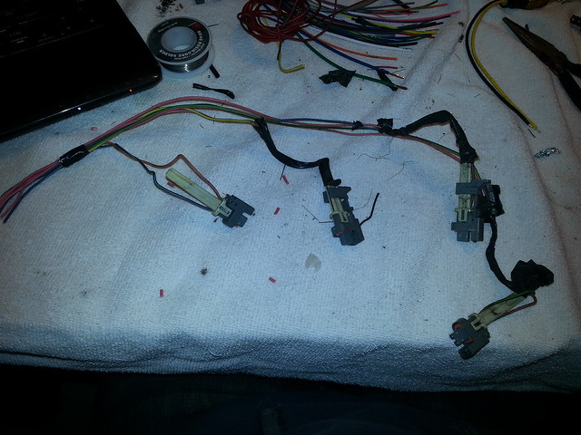
Either reuse the factory connectors (this was off a truck, if you plan to use truck injectors), or switch clips to these (newer style ford clips I think ev6 is the name)
Now, go grab a soda, beer, sweet tea, because your probably thirsty.
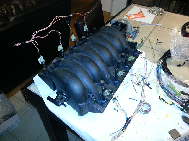
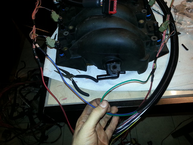
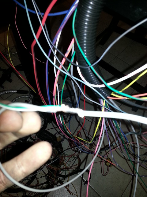
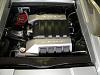
It helps to have your intake pulled where you can set it on a table or work bench and mock everything up.
I put the injectors in half assed and set injector wiring on it (note, wires havent be loomed or routed to not look like butt.
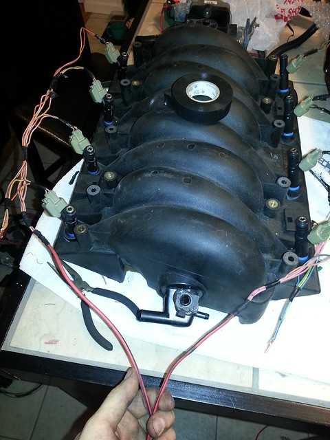
Repeat for the other side of injector clips. Keep in mind that injectors are solenoids. When power is on (key on), and signal (from pcm) sends ground to injector, it opens. So in this case, my power wires were farthest away from the snap clip, so that's where I routed my power wires, and signal wires to the other.
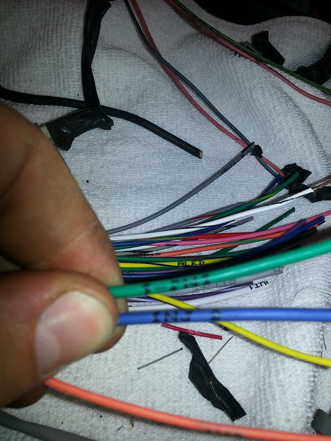
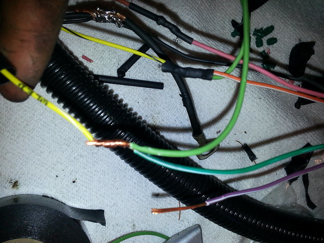
Now you will have 8 wires per side. 4 will be pink, the others are purple, blue, green and orange(red on earlier harnesses) I believe.
Take one bank's pink wires (all 4) and run a power wire to them from the fuse box. I used a 10-12 ga wire, it's probably overkill but it will work.
Do this for both sides
Remember the INJ1 INJ2 green and blue wires? You need these now. Again, since it's batch fire, one side is for one injector, the other is for you guess it, the other bank.
Now you're all done with Crank angle sensor, and all 8 injectors YAY!!
Lets move onto ignition.. it's not tricky but just make sure you read a few times to get them correct.
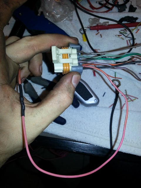
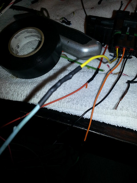
One note: depending on year of coil pack plug, all the colors are the same, except later models may have an orange wire in place of red. Doesn't really matter as long as they are positioned correctly. early and late model shown here:
Start off by finding the pink wires on the coil pack harness connectors. This will provide 12v to coils. Run a power wire from fuse box.
Next find the black wires on the coil pack harness connectors. These will be grounded. Also find the two larger ground wires in the microsquirt harness. I joined all four of these wires to one fat ground wire with a hoop to ground to the head.
Note: the orange wire shown here may be red on earlier harnesses.
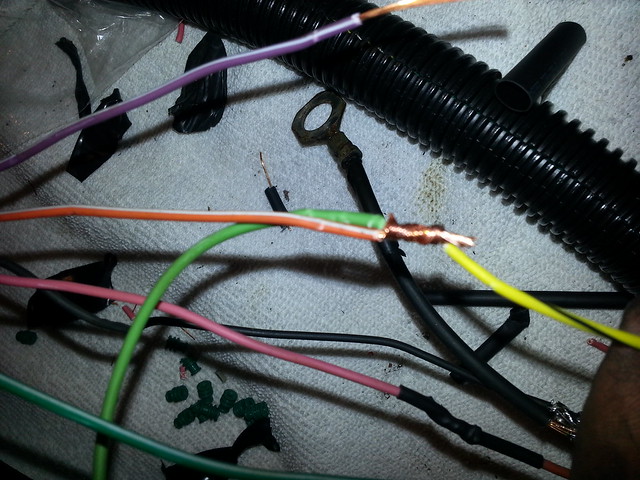
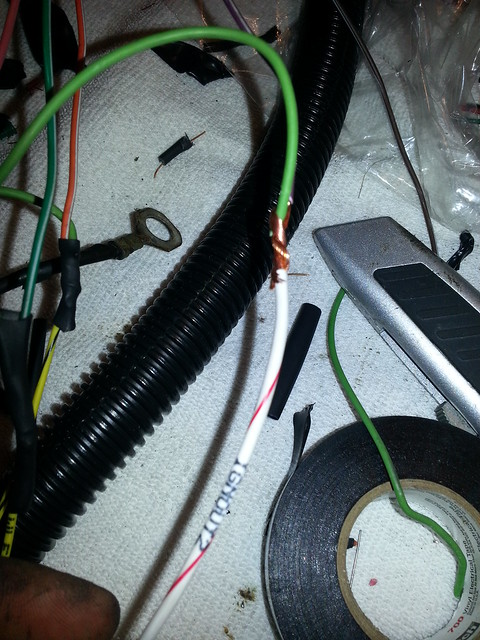
Find the blue wire on the drivers side harness. Note: I used green only to extend length to other side
Connect it to orange on passenger side (may be red on earlier harness)
Connect these two wires driver blue and passenger orange (or red) to Microsquirt yellow/black
Find the orange (or red) wire on drivers side harness, extend it to passenger side. Connect it to green on passenger.

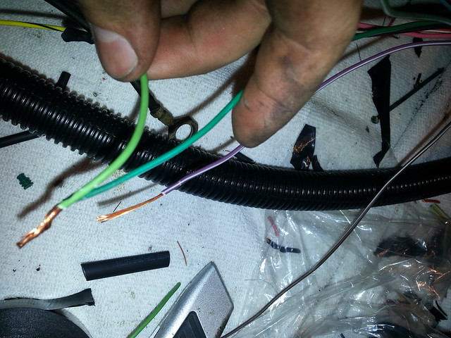
Connect these, orange (or red) from driver, and green from passenger to yellow/white on microsquirt
Next find green on drivers side harness. Connect it to to purple on passenger side
Take both of these green from driver, and purple on passenger and connect them to white/red from microsquirt harness
next take purple from drivers side, connect it to blue on passenger side.
Connect these to white from microsquirt

Now you're all done with Crank angle sensor, Injectors, and coil wiring.
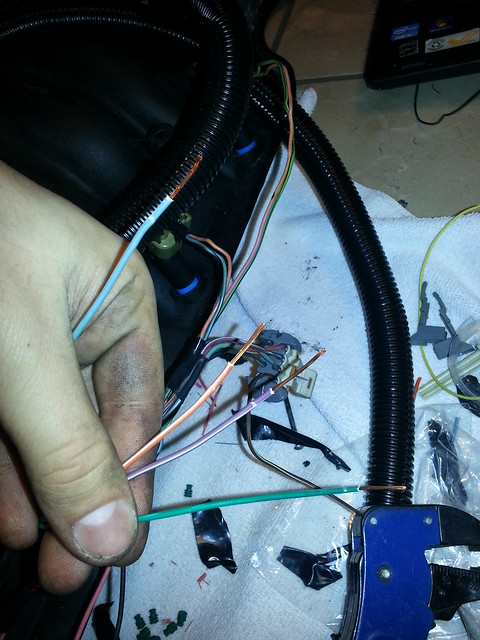
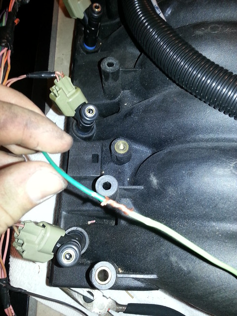
Next up is the AIT sensor. Very easy as colors match. Orange wire labeled AIT goes to the orange on AIT sensor. The black wire from AIT goes to sensor ground (will wire later)
Now Crank angle sensor, injectors, coils and AIT are done.
The next is Coolant Temp. Is it also color correct. My picture turned out like donkey doo doo, but find the yellow wire labeled Coolant and match it to the yellow cts wire. The black wire will go to sensor ground (wire later).
Now CAS, INJ, Coils, AIT and CTS are done.
Next up is the Throttle Position Sensor TPS
Find the blue wire on TPS plug, connect it to tps signal on microsquirt ( believe blue also)
The tan (could be black) wire from TPS plug goes to sensor ground (wired later)
The grey wire from TPS plug goes to 5v reference, shared with MAP
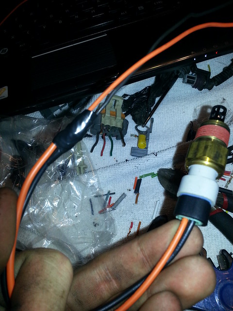
Find your MAP, connect the middle pin orange and connect it to red/green wire from microsquirt harness. Should be labeled MAP
Black wire will go to sensor ground (wired later)

Now connect the TPS Ref 5v wire to grey on TPS plug and yellow (or the last wire left on map)
Note yellow goes to a light blue wire, but only for extension purposes. It connects to TPS reference
Now you're done with CAS, INJ, Coils, AIT, CTS, TPS, and MAP.
Alternate (which I haven't wired yet is o2 sensor) pink wire on microsquirt goes to 02 signal if you are running narrowband.
You should have a total of these power wires: Injectors, Coils, CAS, 12v to pcm.
Outputs reccomended to be wired are for TACH, bootloader and fuel pump.
After testing the harness for continuity at each pin, or hooking it up and loading up MS, you can move tps and see if it moves and changes.. Good indication that things are wired correctly.
I am currently working on a fox-chassis 5.3/76mm/th400/8.8/microsquirt setup and have build 90% of my harness and took step by step pictures as WHAT I BELIEVE TO BE CORRECT. I hope Denmah will review this and see any inconsistencies.
Start by just reviewing what all is needed for the Microsquirt:
Required:
Microsquirt
MS harness
Map sensor + pigtail
Coolant Temp + pigtail
Intake air temp + pigtail
Injectors + pigtails x 8
Throttle position sensor + pigtail
Coils + pigtail x2 (bank harness for lsx)
Optional:
02 sensor (recommended)
I ordered all of my supplies from EFI source..
I also clipped off the whole injector/coil harness from each side to give me a rough estimate on length to get going.. looked like this..
Next, find your Microsquirt computer.. flip it to the backside and find the 4 small screws. Open it up
On the back you will see pins for each piece of the MS harness. Start by taking a 1k 1/4watt resistor, and attaching the leads as shown...
Now take 2 4.7k 1/4watt resistors and attach to pins shown..
Note, my pin #1 is soldered like complete ***, ill probably go back and fix it but you get the idea...
Adding these jumpers are for the correct signal for crank sensor and adding two additional circuits for a v8 in wasted spark ignition
Put the case back together and look for vr1+, this is a shielded wire, but all that is attached is the red wire. This goes to yellow wire on the crank sensor pigtail. (signal)
The purple wire (which i indicated by looping) will go to sensor ground (later on in walkthrough)
The last wire, green, will have a 12v source connected to it from fuse box
Crank sensor is done!
Next find the wires from Microsquirt harness that says INJ1 and INJ2, since this will be a batch fire ignition system, one side is fired, and then the other side.. hence all signals for one side of the engine will be connected to either the green, or the blue respectively.
Next, find your injector harness including clips. I cut this off the donor harness as it makes it easier to visualize how long they need to be, and it also helps keep colors somewhat coordinated.
Either reuse the factory connectors (this was off a truck, if you plan to use truck injectors), or switch clips to these (newer style ford clips I think ev6 is the name)
Now, go grab a soda, beer, sweet tea, because your probably thirsty.
It helps to have your intake pulled where you can set it on a table or work bench and mock everything up.
I put the injectors in half assed and set injector wiring on it (note, wires havent be loomed or routed to not look like butt.
Repeat for the other side of injector clips. Keep in mind that injectors are solenoids. When power is on (key on), and signal (from pcm) sends ground to injector, it opens. So in this case, my power wires were farthest away from the snap clip, so that's where I routed my power wires, and signal wires to the other.
Now you will have 8 wires per side. 4 will be pink, the others are purple, blue, green and orange(red on earlier harnesses) I believe.
Take one bank's pink wires (all 4) and run a power wire to them from the fuse box. I used a 10-12 ga wire, it's probably overkill but it will work.
Do this for both sides
Remember the INJ1 INJ2 green and blue wires? You need these now. Again, since it's batch fire, one side is for one injector, the other is for you guess it, the other bank.
Now you're all done with Crank angle sensor, and all 8 injectors YAY!!
Lets move onto ignition.. it's not tricky but just make sure you read a few times to get them correct.
One note: depending on year of coil pack plug, all the colors are the same, except later models may have an orange wire in place of red. Doesn't really matter as long as they are positioned correctly. early and late model shown here:
Start off by finding the pink wires on the coil pack harness connectors. This will provide 12v to coils. Run a power wire from fuse box.
Next find the black wires on the coil pack harness connectors. These will be grounded. Also find the two larger ground wires in the microsquirt harness. I joined all four of these wires to one fat ground wire with a hoop to ground to the head.
Note: the orange wire shown here may be red on earlier harnesses.
Find the blue wire on the drivers side harness. Note: I used green only to extend length to other side
Connect it to orange on passenger side (may be red on earlier harness)
Connect these two wires driver blue and passenger orange (or red) to Microsquirt yellow/black
Find the orange (or red) wire on drivers side harness, extend it to passenger side. Connect it to green on passenger.
Connect these, orange (or red) from driver, and green from passenger to yellow/white on microsquirt
Next find green on drivers side harness. Connect it to to purple on passenger side
Take both of these green from driver, and purple on passenger and connect them to white/red from microsquirt harness
next take purple from drivers side, connect it to blue on passenger side.
Connect these to white from microsquirt
Now you're all done with Crank angle sensor, Injectors, and coil wiring.
Next up is the AIT sensor. Very easy as colors match. Orange wire labeled AIT goes to the orange on AIT sensor. The black wire from AIT goes to sensor ground (will wire later)
Now Crank angle sensor, injectors, coils and AIT are done.
The next is Coolant Temp. Is it also color correct. My picture turned out like donkey doo doo, but find the yellow wire labeled Coolant and match it to the yellow cts wire. The black wire will go to sensor ground (wire later).
Now CAS, INJ, Coils, AIT and CTS are done.
Next up is the Throttle Position Sensor TPS
Find the blue wire on TPS plug, connect it to tps signal on microsquirt ( believe blue also)
The tan (could be black) wire from TPS plug goes to sensor ground (wired later)
The grey wire from TPS plug goes to 5v reference, shared with MAP
Find your MAP, connect the middle pin orange and connect it to red/green wire from microsquirt harness. Should be labeled MAP
Black wire will go to sensor ground (wired later)
Now connect the TPS Ref 5v wire to grey on TPS plug and yellow (or the last wire left on map)
Note yellow goes to a light blue wire, but only for extension purposes. It connects to TPS reference
Now you're done with CAS, INJ, Coils, AIT, CTS, TPS, and MAP.
Alternate (which I haven't wired yet is o2 sensor) pink wire on microsquirt goes to 02 signal if you are running narrowband.
You should have a total of these power wires: Injectors, Coils, CAS, 12v to pcm.
Outputs reccomended to be wired are for TACH, bootloader and fuel pump.
After testing the harness for continuity at each pin, or hooking it up and loading up MS, you can move tps and see if it moves and changes.. Good indication that things are wired correctly.
Last edited by superbean; 02-18-2013 at 02:21 PM.
 02-18-2013, 12:20 PM
#2
TECH Apprentice
Thread Starter
Join Date: Apr 2011
Posts: 390
Likes: 0
Received 0 Likes
on
0 Posts
Load one of Denmah's tunes here and follow the steps. Should be close enough to get it started and running! https://ls1tech.com/forums/forced-in...anics-how.html
I hope this helps anyone wanting to tackle this. Including stopping for dinner and taking pictures it took only about four hours total. Not bad at all considering a factory harness conversion usually takes me 10 - 12 hours!
-Randall
I hope this helps anyone wanting to tackle this. Including stopping for dinner and taking pictures it took only about four hours total. Not bad at all considering a factory harness conversion usually takes me 10 - 12 hours!
-Randall

 02-18-2013, 03:13 PM
#5

yeah everything looks great! thanks for adding pictures to the process haha
maybe one day when i build one i will do a video and try not to make it confusing but show you guys how i wire it.
one trick i like to do is pull the 12v power wire for the ecu back a bit to wire it to the crank position sensor, then i cut it, splitting it in two about 1ft out, then i take both wires and put them in a spade into my fuse box, with about 5amps or less, this powers the ecu and then powers the crank position sensor without wasting wire or needing to run any extras. pretty neat, safe to fuse them both on the same wire since they are both very low power usage.
 02-19-2013, 02:03 AM
#7
Staging Lane
iTrader: (1)

Join Date: Jul 2009
Location: Springfield,Ohio
Posts: 60
Likes: 0
Received 0 Likes
on
0 Posts
As a car audio installer it's seems simple enough with step by step directions. I might try this and hopefully get it right. Nice right up and thanks for sharing your knowledge
Trending Topics
 02-19-2013, 11:15 AM
#9
TECH Apprentice
Thread Starter
Join Date: Apr 2011
Posts: 390
Likes: 0
Received 0 Likes
on
0 Posts
Honestly I think this is almost easier than wiring a stereo .. everything is labeled, and 1/2 the colors match up as GM sensors are typically used because they are cheap!
 02-20-2013, 11:31 AM
#11
TECH Apprentice
Thread Starter
Join Date: Apr 2011
Posts: 390
Likes: 0
Received 0 Likes
on
0 Posts
https://ls1tech.com/forums/forced-in...anics-how.html
02-20-2013, 12:07 PM
#12
TECH Apprentice
Thread Starter
Join Date: Apr 2011
Posts: 390
Likes: 0
Received 0 Likes
on
0 Posts
For an overall idea of what you will be doing, I found this diagram helpful...

If picture doesn't work.. use the url....
Microsquirt Schematic
If picture doesn't work.. use the url....
Microsquirt Schematic
Last edited by superbean; 02-21-2013 at 11:21 AM.
04-28-2013, 07:59 PM
#13
Teching In
Join Date: Jan 2013
Location: Raleigh, NC
Posts: 31
Likes: 0
Received 0 Likes
on
0 Posts
Nice write up...that helped a bunch (I'm going to be wiring one up this week). Both this and Denmah's write ups refer to the "sensor ground" for the crank sensor ...I'm assuming this is the white/black wire labeled "ground sensor" (where all of the other sensors are grounded)?
04-28-2013, 08:18 PM
#14
TECH Regular
iTrader: (2)
Join Date: Dec 2009
Location: Austin Texas
Posts: 414
Likes: 0
Received 0 Likes
on
0 Posts
Yes all your sensors will use the blk/wht sensor ground wire.
I just finished a 58x LS4 install running Microsquirt on my Lambo Diablo kit car.
Although Im not completely done with the tuning Im very happy with the Microsquirt so far.

I just finished a 58x LS4 install running Microsquirt on my Lambo Diablo kit car.
Although Im not completely done with the tuning Im very happy with the Microsquirt so far.


 06-11-2013, 06:37 PM
#17
TECH Apprentice
Thread Starter
Join Date: Apr 2011
Posts: 390
Likes: 0
Received 0 Likes
on
0 Posts
All sensors grounds need to go to sensor ground in the microsquirt harness. The only one that doesn't necessarily need to go to sensor ground is for the coils..
06-12-2013, 07:05 PM
#18
 09-24-2013, 11:52 AM
#20
TECH Apprentice
Thread Starter
Join Date: Apr 2011
Posts: 390
Likes: 0
Received 0 Likes
on
0 Posts
There are companies that make stand alone controllers for 4L80e. If you want to keep the transmission fully electronic I would suggest using a factory pcm.
Microsquirt is awesome for drag cars with hydraulic non electronic transmissions.
Microsquirt is awesome for drag cars with hydraulic non electronic transmissions.