
DIY Head Porting Project (5.3 Heads) Lots-O-Pics 56k Beware
 12-16-2006, 01:12 PM
#1

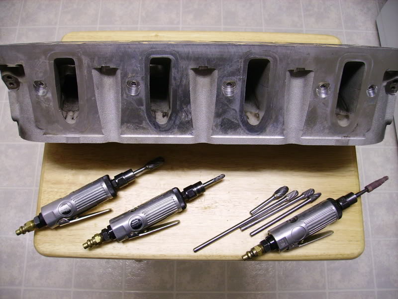
I thought you guys might like to see some progress pics of my DIY head porting I started a couple weeks ago. I think I took the intake runner too large, as the low lift numbers look a bit soft. I'd appreciate some pointers/tips from those that have done this before with good success. This is my first set of LSx heads, but I'm not new to head porting. I've ported many sets of LT1 heads in the past, getting high 260's, to mid 270's out of them.
Had these 5.3's flowed with the stock, super-tiny 1.89/1.55 valves before I started the porting. The guy that flowed them wants to learn more about the LSx stuff, so he has offered to flow test them for me for FREE if I share my porting techniques with him. It's a great deal for me considering he normally charges $60/chamber, per flow test. I was shooting for numbers in the mid 290 range for the intake, and around 220ish for exhaust, both at .500-.550 lift range.
I took many photo's of the progress and I'm still finishing up the rest of the ports. Here are some flow numbers of the stockers with the tiny 1.89/1.55 valves. The intake became turbulent at around .400 lift according to Dennis, the guy that flowed them
Here are the stock flow #'s @ 28":
lift........./ int../ exh
.200...... 136.... 105
.250...... 167.... 121
.300...... 192.... 137
.350...... 211.... 155
.400...... 223.... 171<-- became turbulent on intake side
.450...... 223.... 190
.500...... 224.... 203
.550...... 228.... 213
.600...... 233.... 217
.650...... 237.... 218
.700...... 239.... 221
Here are the "after porting" flow numbers. Please note that the throat cut still needs to be blended into the bowl (it left a ridge), so I'm expecting around a 5cfm bump accross the entire range afterwards. I'm having this chamber re-tested next week, hopefully. As mentioned previously, I think I made the intake runner too large, so the low lift numbers are a bit on the soft side. I'm fairly pleased with the exhaust though, as these heads are planned for a nitrous engine.
lift........./ int../ exh
.200...... 131.... 111
.250...... 160.... 131
.300...... 190.... 149
.350...... 217.... 168
.400...... 240.... 183
.450...... 257.... 201
.500...... 273.... 217
.550...... 283.... 228
.600...... 289.... 235
.650...... 295.... 241
.700...... 298.... xxx
Here's some pics of the stockers as-is before port work:
Many more pics to follow........
Mike
 12-16-2006, 01:14 PM
#2
Here's some "in progress" pics from porting:
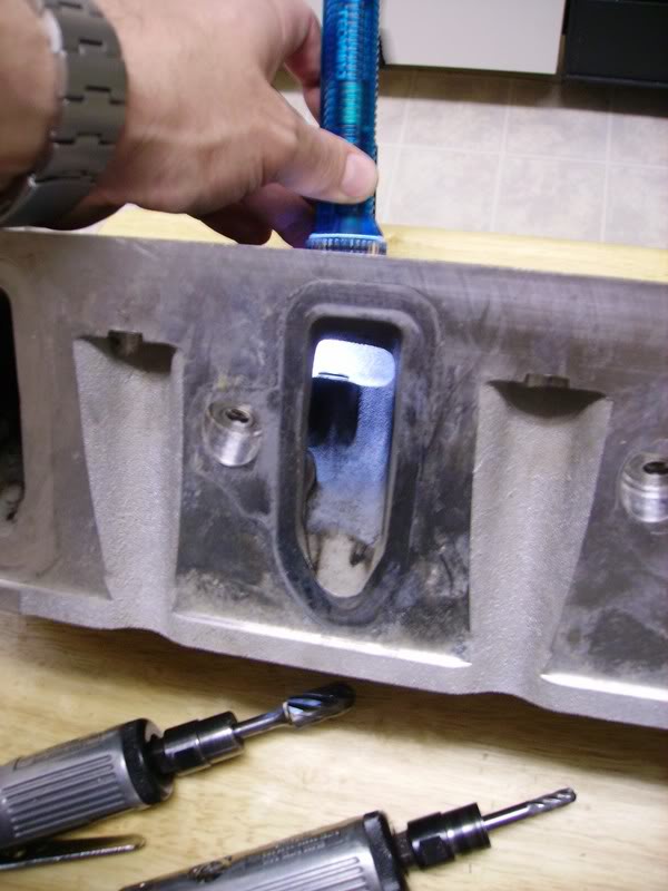
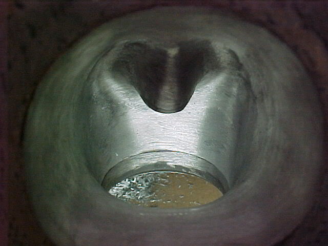
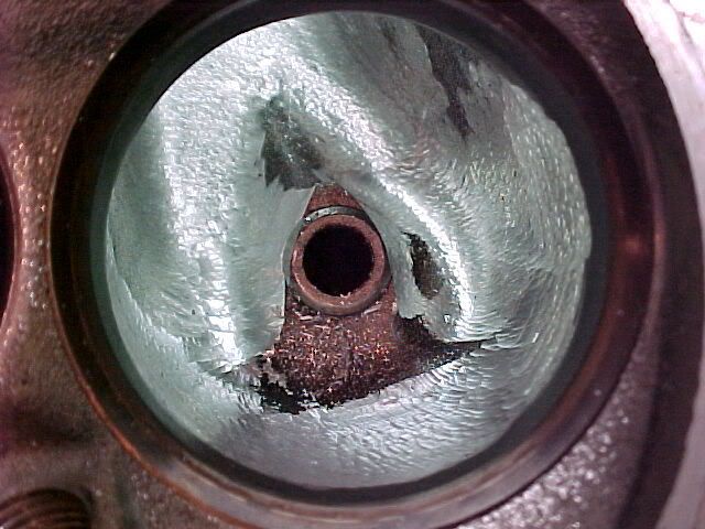
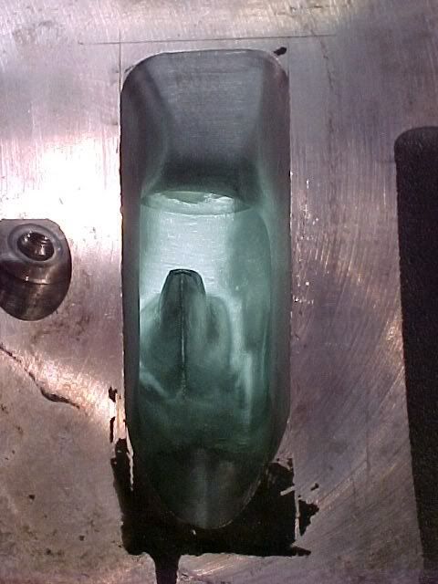
Roughing in the intake entry. Sorry these turned out a bit dark.

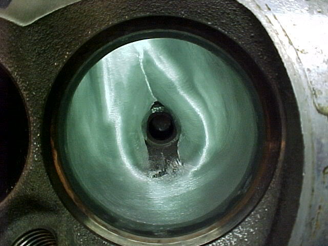
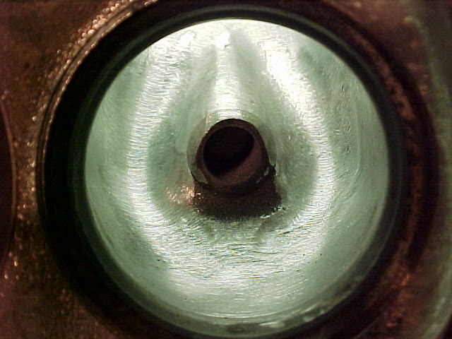
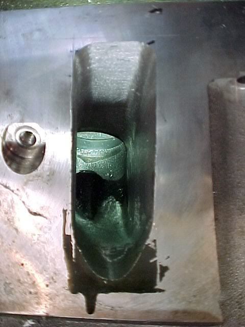
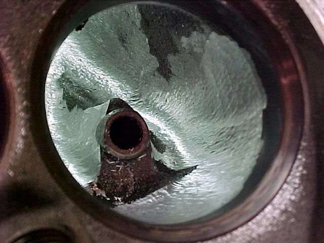
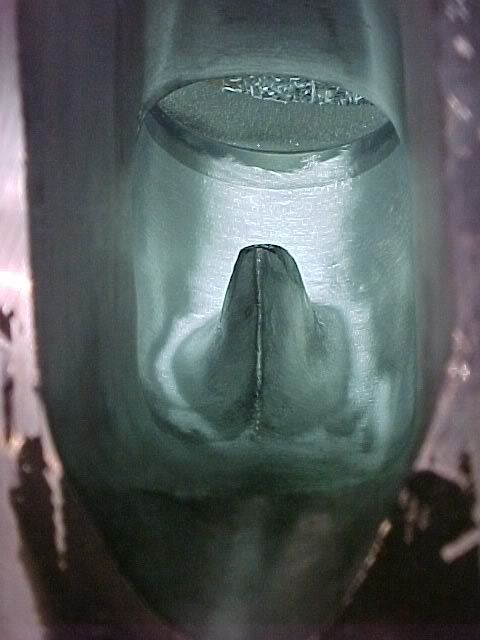
Here I just did some rough shaping in the bowl area, blending the intake porting into the bowl and shaping the valve guide area.

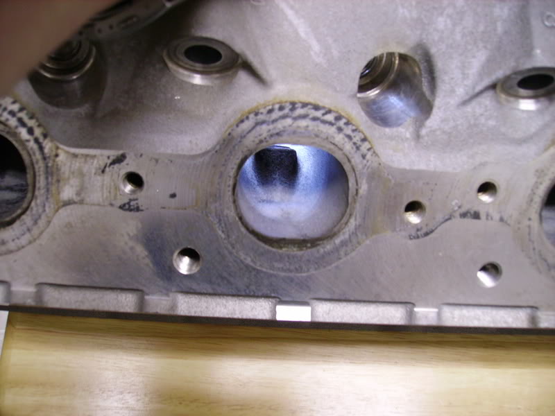
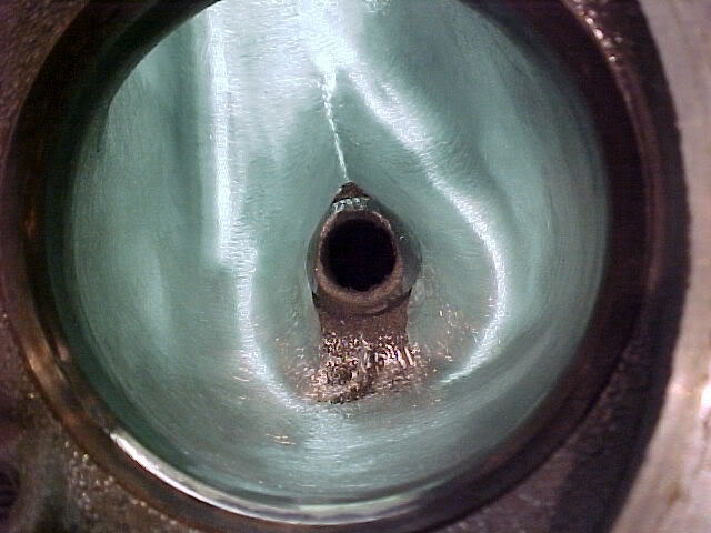
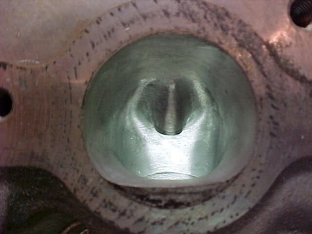
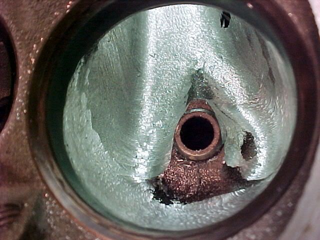
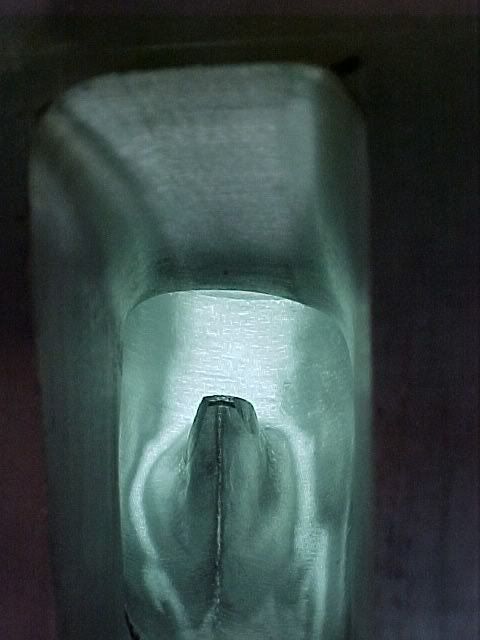
Here's some pics after I completed all the shaping, then hit the entire port/bowl with a cartridge roll. I'm fairly pleased with how this one turned out. These LSx heads are a walk in the park compared to porting an LT1 head. I have about 2.25 hours into this port and it was my first one.


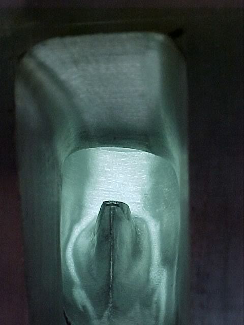
Roughing in the intake entry. Sorry these turned out a bit dark.
Here I just did some rough shaping in the bowl area, blending the intake porting into the bowl and shaping the valve guide area.
Here's some pics after I completed all the shaping, then hit the entire port/bowl with a cartridge roll. I'm fairly pleased with how this one turned out. These LSx heads are a walk in the park compared to porting an LT1 head. I have about 2.25 hours into this port and it was my first one.
The following users liked this post:
Homer_Simpson (12-01-2021)
12-16-2006, 01:17 PM
#3
Here are the pics from porting on the exhaust and chamber.
.
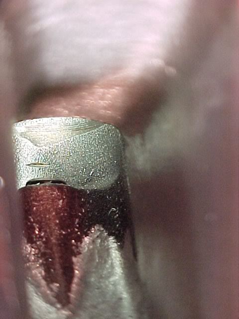
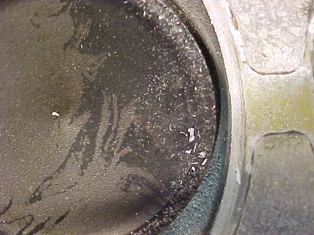
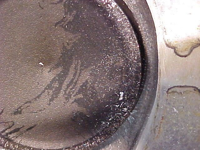
Comparison between the stocker and the ported version.............
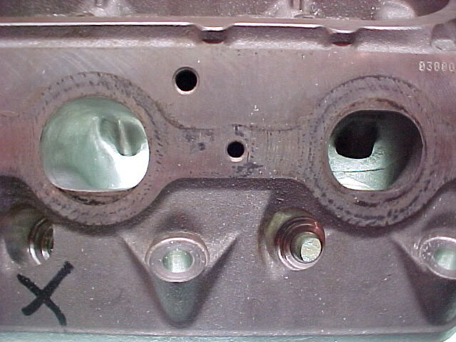
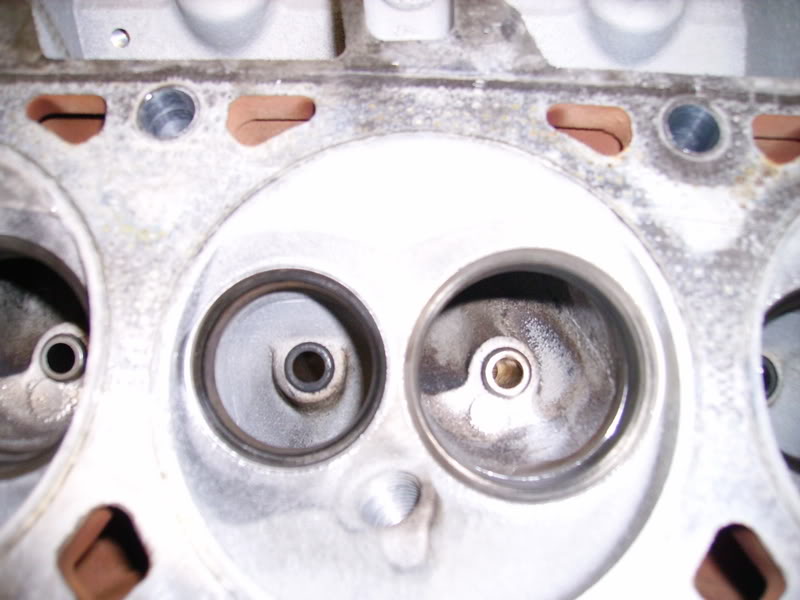
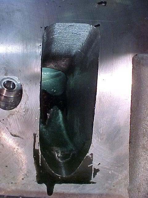
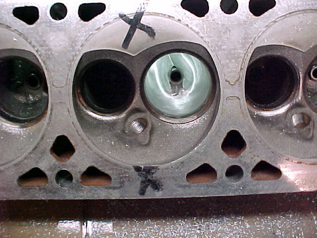
Shot of the chamber with both runners finished up.....
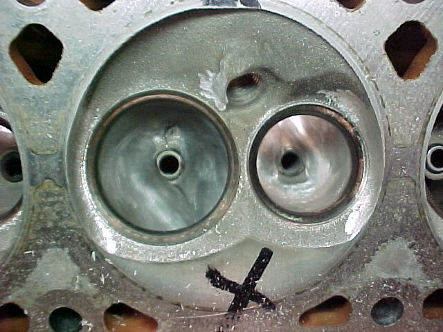
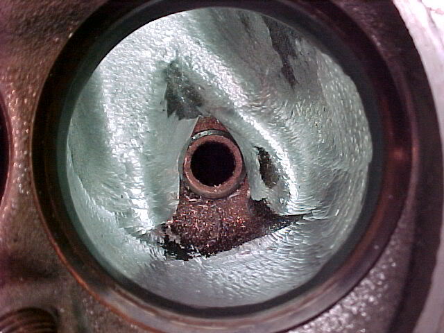
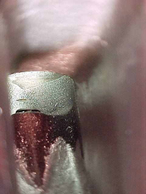
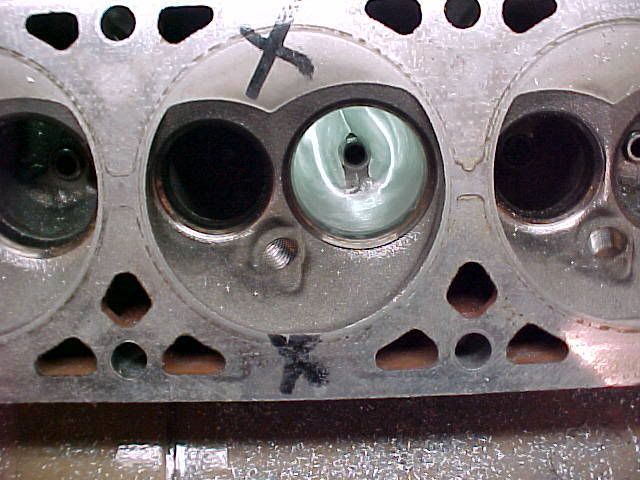
Shrouding of the valve before port work.....
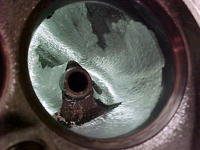
After unshrouding the valve.......
Mike
.
Comparison between the stocker and the ported version.............
Shot of the chamber with both runners finished up.....
Shrouding of the valve before port work.....
After unshrouding the valve.......
Mike
12-16-2006, 01:35 PM
#5

Looks like your works compares quite well to PP 5.3 St II heads:
Stage II 1020 Superflow Bench 3.905 bore
Great for a first effort - imagine what you'll be able to do after refining the process. Also, what valve sizes & cuts were used? Any backcut on the valves?
Stage II 1020 Superflow Bench 3.905 bore
Code:
Lift   2.02" Intake   1.57" Exhaust

.100       67 cfm     61 cfm
.200      133 cfm   108 cfm
.300      194 cfm   147 cfm
.400      242 cfm   183 cfm
.500      274 cfm   205 cfm
.550      290 cfm   213 cfm
.600      296 cfm   220 cfm
12-16-2006, 01:43 PM
#6
Originally Posted by hammertime
Looks like your works compares quite well to PP 5.3 St II heads:
Stage II 1020 Superflow Bench 3.905 bore
Great for a first effort - imagine what you'll be able to do after refining the process. Also, what valve sizes & cuts were used? Any backcut on the valves?
Stage II 1020 Superflow Bench 3.905 bore
Code:
Lift   2.02" Intake   1.57" Exhaust

.100       67 cfm     61 cfm
.200      133 cfm   108 cfm
.300      194 cfm   147 cfm
.400      242 cfm   183 cfm
.500      274 cfm   205 cfm
.550      290 cfm   213 cfm
.600      296 cfm   220 cfm
Mike
Trending Topics
12-16-2006, 06:32 PM
#8
Registered User
iTrader: (15)

Join Date: Aug 2005
Location: BTR, La
Posts: 1,363
Likes: 0
Received 0 Likes
on
0 Posts
Wow, those look like some big ports. Did you measure the volume of a few of them? The peak flow numbers look really good using those 2.02" valves. Are you going to do a before/after dyno test?
Ben T.
Ben T.
12-16-2006, 07:11 PM
#9
Originally Posted by Studytime
Wow, those look like some big ports. Did you measure the volume of a few of them? The peak flow numbers look really good using those 2.02" valves. Are you going to do a before/after dyno test?
Ben T.
Ben T.
I didn't CC any of the ports because they are what they are lol... Nothing I can do to change them now. If I port another set, I'll try to keep the port size down, through the narrow part of the intake runner.
These were tested with 2.00"/1.55" valves, not 2.02".
As for the dyno testing, I don't have anything to compare with because I'm building this LS1 for my engine swap in my 97.

Mike
12-16-2006, 07:22 PM
#10
Registered User
iTrader: (15)
Join Date: Aug 2005
Location: BTR, La
Posts: 1,363
Likes: 0
Received 0 Likes
on
0 Posts
I stand corrected, 2.00" valves. I was just curious on how big they were. I agree, one slip with a carbide burr and the metal's not going back!  Atleast you didn't hit water. They look really good, not what I'd call diy. I think you're a step above that.
Ben T.
Atleast you didn't hit water. They look really good, not what I'd call diy. I think you're a step above that.Ben T.
12-17-2006, 08:48 PM
#12
well the flow #s look really good, and the quality of the work looks excellent compared to mine. I think mine looks ok, but yours just seem to be a bit better job of being smooth/even. one question though, I was told by a couple diff. pro porters to leave the ramp alone on the intake side. clean it up, smooth it off, but leave it there. youve completly removed it. have you inquired about that before you did that? guess its there to promote turbulence at the point of where the fuel meets with the incoming air and it improves the quality of the atomization of fuel.
Im not sure what the diff. are between the 5.3 and the 853 heads? the ports look very similar atleast looking at the before shots. what size cam are you goin with? just curious. hopefully my next set (already sitting here, ready to go) will turn out some flow #s like that.
Im not sure what the diff. are between the 5.3 and the 853 heads? the ports look very similar atleast looking at the before shots. what size cam are you goin with? just curious. hopefully my next set (already sitting here, ready to go) will turn out some flow #s like that.
12-18-2006, 12:19 PM
#13
Originally Posted by Irocss85
well the flow #s look really good, and the quality of the work looks excellent compared to mine. I think mine looks ok, but yours just seem to be a bit better job of being smooth/even. one question though, I was told by a couple diff. pro porters to leave the ramp alone on the intake side. clean it up, smooth it off, but leave it there. youve completly removed it. have you inquired about that before you did that? guess its there to promote turbulence at the point of where the fuel meets with the incoming air and it improves the quality of the atomization of fuel.
Im not sure what the diff. are between the 5.3 and the 853 heads? the ports look very similar atleast looking at the before shots. what size cam are you goin with? just curious. hopefully my next set (already sitting here, ready to go) will turn out some flow #s like that.
Im not sure what the diff. are between the 5.3 and the 853 heads? the ports look very similar atleast looking at the before shots. what size cam are you goin with? just curious. hopefully my next set (already sitting here, ready to go) will turn out some flow #s like that.
I'm not positive on the cam selection just yet, but it will be in the G5X4 category, or a custom grind.
Mike
12-18-2006, 09:45 PM
#15
sorry for the size, Im retarded and I have no idea how to change the size of a picture.
no, by ramp I mean the part on the left side of the intake roof. when the air goes around the valve guide on the one side, it smacks into the air tumbeling into it on the other side. see the line below. thats the end of the "ramp". not sure what its really called.
seeing your pics made me go back and smooth the chambers again. now they just need a final cleaning and to assemble them.
how many hours do you imagine you got into the whole set? I think Im in the 20+ hour range now. no idea though really since its been such a long process. started these heads months ago really since I got them from a friend.
but this is my first LS1 set also, and Ive learned alot. next set wont take anywhere near as much time. now that I know what shape I can make things w/o worry.
as for the cam, whats the g5x3 range? my cam is a cross between the x3 and MS4. hopeing to have it back together in a few weeks.
[IMG] [/IMG]
chris
no, by ramp I mean the part on the left side of the intake roof. when the air goes around the valve guide on the one side, it smacks into the air tumbeling into it on the other side. see the line below. thats the end of the "ramp". not sure what its really called.
seeing your pics made me go back and smooth the chambers again. now they just need a final cleaning and to assemble them.
how many hours do you imagine you got into the whole set? I think Im in the 20+ hour range now. no idea though really since its been such a long process. started these heads months ago really since I got them from a friend.
but this is my first LS1 set also, and Ive learned alot. next set wont take anywhere near as much time. now that I know what shape I can make things w/o worry.
as for the cam, whats the g5x3 range? my cam is a cross between the x3 and MS4. hopeing to have it back together in a few weeks.
[IMG]
[/IMG] chris
12-18-2006, 10:42 PM
#17
Originally Posted by Irocss85
sorry for the size, Im retarded and I have no idea how to change the size of a picture.
no, by ramp I mean the part on the left side of the intake roof. when the air goes around the valve guide on the one side, it smacks into the air tumbeling into it on the other side. see the line below. thats the end of the "ramp". not sure what its really called.
seeing your pics made me go back and smooth the chambers again. now they just need a final cleaning and to assemble them.
how many hours do you imagine you got into the whole set? I think Im in the 20+ hour range now. no idea though really since its been such a long process. started these heads months ago really since I got them from a friend.
but this is my first LS1 set also, and Ive learned alot. next set wont take anywhere near as much time. now that I know what shape I can make things w/o worry.
as for the cam, whats the g5x3 range? my cam is a cross between the x3 and MS4. hopeing to have it back together in a few weeks.
chris
no, by ramp I mean the part on the left side of the intake roof. when the air goes around the valve guide on the one side, it smacks into the air tumbeling into it on the other side. see the line below. thats the end of the "ramp". not sure what its really called.
seeing your pics made me go back and smooth the chambers again. now they just need a final cleaning and to assemble them.
how many hours do you imagine you got into the whole set? I think Im in the 20+ hour range now. no idea though really since its been such a long process. started these heads months ago really since I got them from a friend.
but this is my first LS1 set also, and Ive learned alot. next set wont take anywhere near as much time. now that I know what shape I can make things w/o worry.
as for the cam, whats the g5x3 range? my cam is a cross between the x3 and MS4. hopeing to have it back together in a few weeks.
chris
 Did I say completely, oh ya,,, COMPLETELY.
FWIW, I've documented every step of this porting process, and I'm going to be doing a full detailed write-up, complete with dimensions, when I'm finished.
I probably have about 18 hours into it so far. I have one head just about completely finished, including chamber work and unshrouding the valves etc. I have one complete chamber (intake/exhaust) finished on the other head, so I have 3 more intake/exhaust and chambers left to finish. They're going pretty fast now though, so I figure I have another 8 hours left +/- 1 hour.
Not positive on the X3, 236ish or so? The X4 is bigger still, prolly around 239-242ish.
Is that a pic of your chamber? If so, you could roll over the spark plug boss near the intake valve. Also, have you unshrouded the valves in the chamber yet? If not, that'll help your low lift numbers.
Mike
12-19-2006, 08:23 AM
#18
TECH Senior Member
iTrader: (15)

Join Date: Nov 2001
Location: Grand Prairie, TX
Posts: 5,109
Likes: 0
Received 0 Likes
on
0 Posts
Originally Posted by Mikey 97Z M6
Here's some "in progress" pics from porting:
Roughing in the intake entry. Sorry these turned out a bit dark.

Here I just did some rough shaping in the bowl area, blending the intake porting into the bowl and shaping the valve guide area.
Here's some pics after I completed all the shaping, then hit the entire port/bowl with a cartridge roll. I'm fairly pleased with how this one turned out. These LSx heads are a walk in the park compared to porting an LT1 head. I have about 2.25 hours into this port and it was my first one.

Roughing in the intake entry. Sorry these turned out a bit dark.
Here I just did some rough shaping in the bowl area, blending the intake porting into the bowl and shaping the valve guide area.
Here's some pics after I completed all the shaping, then hit the entire port/bowl with a cartridge roll. I'm fairly pleased with how this one turned out. These LSx heads are a walk in the park compared to porting an LT1 head. I have about 2.25 hours into this port and it was my first one.
Looking at the heads theres a few mistakes that you really should address...The most important thing is the guide area and the ridge. Also the floor and walls dont look very flat from the pics...Last thing...DO SOME CHAMBER WORK...thats a KEY area in these cylinder heads. Other then that...Looks like its makeing the flow bench somewhat happy but it may not run a number at the track for you.
12-19-2006, 01:50 PM
#19
Originally Posted by V6 Bird
Looking at the heads theres a few mistakes that you really should address...The most important thing is the guide area and the ridge. Also the floor and walls dont look very flat from the pics...Last thing...DO SOME CHAMBER WORK...thats a KEY area in these cylinder heads. Other then that...Looks like its makeing the flow bench somewhat happy but it may not run a number at the track for you.
The pics of the chambers you see in this thread are unfinished.
Mike
12-19-2006, 02:28 PM
#20
TECH Senior Member
iTrader: (15)
Join Date: Nov 2001
Location: Grand Prairie, TX
Posts: 5,109
Likes: 0
Received 0 Likes
on
0 Posts
Originally Posted by Mikey 97Z M6
That is the second time I've heard that about the ridge I left on the guide. Is that substantiated with a flow bench data, and if so, what are the effects? Also, and I'm not trying to be a jerk here, but what is your porting background? The only reason I ask, is because I'm relatively new to the LS1 scene so I truly don't know you, or your background so I don't necesarrily trust your porting tips just yet.
The pics of the chambers you see in this thread are unfinished.
Mike
The pics of the chambers you see in this thread are unfinished.
Mike

A flowbench is used as a measuring device. if you want to see some really trick **** going on in the ports, put them on a wetflow bench and then fix the issues.
