
QTP Exhaust Cutout Controller Mod
 08-30-2008, 04:12 AM
#1
Teching In
Thread Starter
iTrader: (1)
Join Date: Sep 2007
Location: Tucson, AZ
Posts: 14
Likes: 0
Received 0 Likes
on
0 Posts
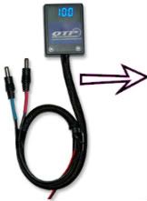
Alright guys so this is for everyone who has a QTP electric cut out and wants the controller but doesn’t want that blue box mounted to the dash…
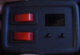
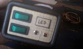
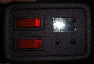
I did this little mod a while ago and have been running it in my car for a month or so now to make sure it works well before I post it up here for everyone else to try. Here is a picture of what the final project will look like when you’re all done.
VIDEO
NOTE:
If you feel like you’re in over your head reading this then you should probably not try this mod. I will attempt to walk you through step by step but it will require some soldering, and some bondo work to make it look like it was done by the factory.
Please read the complete writeup first, then attempt the modifications. Otherwise steps can be very confusing.
*Using this method the QTP controller can be assembled back the way it came in the mail with just a few easy steps.
Parts Needed:
-QTP Electric Exhaust Dump Controller
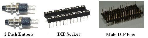
-2 Pushbuttons (see pic)
-DIP Socket; going to need a 12pin socket
-Male to Male DIP Socket
-Wire
-Piece of CLEAR plexiglass
-Light box, or a window
-Bondo
-Sandpaper
-Superglue
-“Night Shades” Tinting paint
-Interior automotive texture in a can
-Primer and interior paint.
…I think that’s about it... lol
Here we go!!
Step 1: Disassembly
Disassembling the controller is not that hard it is only held together with one screw, but where you ask!?!? This screw is located underneath the QTP sticker. You can either remove the sticker or just poke through it. Your choice. Once the cover is removed there are 2 little silver buttons, the bottom half and the top shell. The first time I took it apart I realized that all of the electrical components of the controller are “locked” into the bottom shell by what looks like a jb weld substance. Do not try to remove the circuit board you will ruin your controller. Lucky for us all the things we need are located right on top but we will get to that part later. To remove the Display you will need to CAREFULLY pull directly up on it and it will “slide” out of its DIP sockets.
BE VERY CAREFUL WITH THE DISPLAY! THERE ARE SMALL PINS ON THE BACK THAT WILL BREAK OFF VERY EASLY! IF ONE BREAKS OFF YOU WILL HAVE TO BUY A NEW DISPLAY!
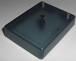
Below is a picture of the top shell, with the buttons and the scew:
Step 2: Choosing the “best” location
First you have to choose where you are going to put the controller. This will be MUCH easier if you choose a location that can be removed from the vehicle and worked on somewhere else. Choose a location in your vehicle where there is going to be enough room for the display and your 2 push buttons. In my Camaro I chose the little cubby by the cigarette lighter, but you can choose wherever you want.
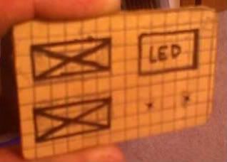
Once you have chosen a spot where you want the controller you are going to need to cut out a piece of plexiglass that will fit into the place you have chosen. To cut the plexiglass you can use a saw or you can “score” the piece and then snap it off. Leave the protective cover on both sides of the piece. Once you have your piece you are going to need to arrange the components on the front of the piece so that they look the way you want them to. I drew a grid with pencil on the protective cover and laid out the switches, buttons and LCD on the gird to make sure it is all aligned. Trace where the components are going to go with a pen. See picture below:
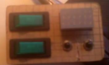
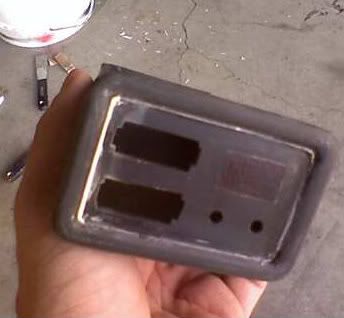
With the components marked on the grid go ahead and cut out the things that need to be cut out, do NOT cut out a hole for the LCD. Drill slowly through the plexiglass to make sure that it doesn’t crack, if it does you will have to start over. In my case I had to cut out holes for the additional toggle switches and drill the holes for the pushbuttons. Carefully test fit the components into their holes. See pictures below:
 ___________
Step 3: Making the display
Unfortunately I do not have a lot of pictures for this section but I will do my best to describe what needs to be done.
*If the components are still placed into the piece remove them for the next steps.
Next we are going to need to mask of the area where the LCD is going to shine through, the protective covering is still on the piece so we will use this as the mask. Using the square that was marked out earlier for the LCD lightly cut through the protective covering making sure that you do not scratch the plexiglass beneath. Once you have cut around the LCD you can remove the rest of the protective covering, leaving the small square for the LCD on the front of the piece of plexiglass. Now we can also remove the back piece of protective covering, be careful at this point because any deep scratches or scuffs will be seen in the finished product.
The front of the LCD has a grey face , and because we don’t want the grey to stick out like a sore thumb this is where the night shades comes into play.
In the picture at the beginning of these instructions you can see some small bubbles this is because I used window tint the first time. Plexiglass is a petroleum based product so when it is in the sun it will release gasses that will bubble your window tint Night shades is the fix to this little mix up.
You are going to want to “tint” the back of the plexiglass piece. You can test the “darkness” by carefully placing the LCD back into the controller and then hooking it up to a battery. Doing this the LCD will light up with an error saying that there is no dump connected. Place the plexiglass piece over the display in any place that is not masked off on the front. Doing this the red is bright enough that it should shine through.
Start with a few coats, it is easy to put more on but a pain in the *** to remove it. Remove the power from the unit if you can still see the gray LCD then you need more coats, be sure not to go to dark where you can’t see the red numbers anymore.
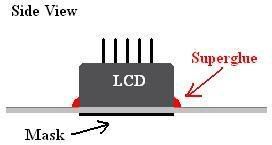
Now you are going to mount the LCD to the piece of plexiglass, remove it from the controller using the instructions above. This is where the light box or a window comes into the procedure. Place the piece on the light box or window with the tinted side facing the light source. The front side still has a small square masked off so there should be a really dark square where there is no light getting through; this is where the LCD should be mounted. If you can not see where the LCD should go turn over the plexiglass and color the masking with a sharpie, this should make it non-transparent. *If you’re a late night worker you might be able to use the oven light to see where the LCD goes Place the LCD over the dark square and put some superglue along the sides of the display. You do not want the superglue to get onto the face of the display, just along the sides. Its kind of like welding you are going to want a nice bead of superglue along the LCD and the plexiglass. See picture below:
.
I did this little mod a while ago and have been running it in my car for a month or so now to make sure it works well before I post it up here for everyone else to try. Here is a picture of what the final project will look like when you’re all done.
VIDEO
NOTE:
If you feel like you’re in over your head reading this then you should probably not try this mod. I will attempt to walk you through step by step but it will require some soldering, and some bondo work to make it look like it was done by the factory.
Please read the complete writeup first, then attempt the modifications. Otherwise steps can be very confusing.
*Using this method the QTP controller can be assembled back the way it came in the mail with just a few easy steps.
Parts Needed:
-QTP Electric Exhaust Dump Controller
-2 Pushbuttons (see pic)
-DIP Socket; going to need a 12pin socket
-Male to Male DIP Socket
-Wire
-Piece of CLEAR plexiglass
-Light box, or a window
-Bondo
-Sandpaper
-Superglue
-“Night Shades” Tinting paint
-Interior automotive texture in a can
-Primer and interior paint.
…I think that’s about it... lol
Here we go!!
Step 1: Disassembly
Disassembling the controller is not that hard it is only held together with one screw, but where you ask!?!? This screw is located underneath the QTP sticker. You can either remove the sticker or just poke through it. Your choice. Once the cover is removed there are 2 little silver buttons, the bottom half and the top shell. The first time I took it apart I realized that all of the electrical components of the controller are “locked” into the bottom shell by what looks like a jb weld substance. Do not try to remove the circuit board you will ruin your controller. Lucky for us all the things we need are located right on top but we will get to that part later.
To remove the Display you will need to CAREFULLY pull directly up on it and it will “slide” out of its DIP sockets.BE VERY CAREFUL WITH THE DISPLAY! THERE ARE SMALL PINS ON THE BACK THAT WILL BREAK OFF VERY EASLY! IF ONE BREAKS OFF YOU WILL HAVE TO BUY A NEW DISPLAY!
Below is a picture of the top shell, with the buttons and the scew:
Step 2: Choosing the “best” location
First you have to choose where you are going to put the controller. This will be MUCH easier if you choose a location that can be removed from the vehicle and worked on somewhere else. Choose a location in your vehicle where there is going to be enough room for the display and your 2 push buttons. In my Camaro I chose the little cubby by the cigarette lighter, but you can choose wherever you want.
Once you have chosen a spot where you want the controller you are going to need to cut out a piece of plexiglass that will fit into the place you have chosen. To cut the plexiglass you can use a saw or you can “score” the piece and then snap it off. Leave the protective cover on both sides of the piece. Once you have your piece you are going to need to arrange the components on the front of the piece so that they look the way you want them to. I drew a grid with pencil on the protective cover and laid out the switches, buttons and LCD on the gird to make sure it is all aligned. Trace where the components are going to go with a pen. See picture below:
With the components marked on the grid go ahead and cut out the things that need to be cut out, do NOT cut out a hole for the LCD. Drill slowly through the plexiglass to make sure that it doesn’t crack, if it does you will have to start over.
In my case I had to cut out holes for the additional toggle switches and drill the holes for the pushbuttons. Carefully test fit the components into their holes. See pictures below:___________Step 3: Making the display
Unfortunately I do not have a lot of pictures for this section but I will do my best to describe what needs to be done.
*If the components are still placed into the piece remove them for the next steps.
Next we are going to need to mask of the area where the LCD is going to shine through, the protective covering is still on the piece so we will use this as the mask. Using the square that was marked out earlier for the LCD lightly cut through the protective covering making sure that you do not scratch the plexiglass beneath. Once you have cut around the LCD you can remove the rest of the protective covering, leaving the small square for the LCD on the front of the piece of plexiglass. Now we can also remove the back piece of protective covering, be careful at this point because any deep scratches or scuffs will be seen in the finished product.
The front of the LCD has a grey face
, and because we don’t want the grey to stick out like a sore thumb this is where the night shades comes into play.In the picture at the beginning of these instructions you can see some small bubbles this is because I used window tint the first time. Plexiglass is a petroleum based product so when it is in the sun it will release gasses that will bubble your window tint
Night shades is the fix to this little mix up. You are going to want to “tint” the back of the plexiglass piece. You can test the “darkness” by carefully placing the LCD back into the controller and then hooking it up to a battery. Doing this the LCD will light up with an error saying that there is no dump connected. Place the plexiglass piece over the display in any place that is not masked off on the front. Doing this the red is bright enough that it should shine through.
Start with a few coats, it is easy to put more on but a pain in the *** to remove it. Remove the power from the unit if you can still see the gray LCD then you need more coats, be sure not to go to dark where you can’t see the red numbers anymore.
Now you are going to mount the LCD to the piece of plexiglass, remove it from the controller using the instructions above. This is where the light box or a window comes into the procedure. Place the piece on the light box or window with the tinted side facing the light source. The front side still has a small square masked off so there should be a really dark square where there is no light getting through; this is where the LCD should be mounted. If you can not see where the LCD should go turn over the plexiglass and color the masking with a sharpie, this should make it non-transparent. *If you’re a late night worker you might be able to use the oven light to see where the LCD goes
Place the LCD over the dark square and put some superglue along the sides of the display. You do not want the superglue to get onto the face of the display, just along the sides. Its kind of like welding you are going to want a nice bead of superglue along the LCD and the plexiglass. See picture below:Continued below
VVVVVVVVVVV
VVVVVVVVVVV
.
Last edited by CoryF; 08-30-2008 at 04:25 AM.
 08-30-2008, 04:14 AM
#2
Teching In
Thread Starter
iTrader: (1)
Join Date: Sep 2007
Location: Tucson, AZ
Posts: 14
Likes: 0
Received 0 Likes
on
0 Posts
^^^^^^^^^^^^^^^^^^^
Continued from above
Continued from above
Step 4: Fabricating the cubby
Now with the display glued into place we need to be VERY careful with it because the pins on the back are very fragile and if one breaks you gotta buy a new LCD.
Now it is time to glue the piece of plexiglass into the cubby. If you are installing into a cubby next to the cigarette lighter you will need to remove the top of the cubby, this can be done with a saw or an air powered cut off wheel. (See my other pictures below so that you don�t remove too much.)Place the piece into your cubby and hold it there with some superglue from the backside. Chances are that it will not fit perfect, but that is where the bondo comes into the game. Once the piece is in the cubby and �tacked� into place with superglue go ahead and fill the gaps around the edges with bondo. This is the part that can become time consuming what you see with the bondo is the final product. Imperfections will be amplified with paint so make sure you get it looking the way you want it.
Sand down the bondo using the sand paper, and also remove any other texture that was previously on the part. Later on we will be spraying on new texture. The masking should still be on the front of the plexiglass, be sure NOT to remove it yet, and make sure that you stay away from it with the sand paper. Below is a picture of what mine looked like after bondo:
Step 5: Texture and paint
Now it is time for the part that we have all been waiting for� Texture and paint
Whether you want to texture or not that is up to you but either way you need to use primer. I recommend SEM HIGH BUILD PRIMER SURFACER (42003) this product will help fill in the small pinhole imperfections in the bondo, and makes for a great first coat. Follow the application directions on the can, and be sure to sand the final product down smooth.
This next part is about the texture, if you do not want to texture your part skip to the paint step. The texture that I used is: SEM TEXTURE COATING (39853) this product will apply to the part to give it a texture very similar to that which came with the car. Follow the application instructions on the can. Remove different part from the car such as the radio bezel and use that as a template on how much texture to apply to your part. Once this is dry be sure to wipe it clean there is a lot of �dusty� overspray texture that does not stick to the part and you want to remove it before you paint.
Now its time for paint, I used another SEM product. At your local automotive paint shop they should have a color to match the color of your interior. I used SEM TRIM BLACK (39143) it matched my interior almost perfectly!
After you have painted the piece you may carefully remove the masking over the �window.� I did not remove the masking until I was completely done just incase something happened or incase I needed to touch up any spots.
Below is another picture of my final product and it shows a close up of the texture:
Step 6: Electrical
Now it is time for the �hard part� the electrical�
As I said before the circuit board is glued to the bottom half of the shell so there is no way to remove it, don�t try most likely it will break something and then you will have a nice blue paper weight.
Buttons:
Let�s start with the �easier� part the buttons, for this you will need a small 3 conductor wire. I don�t recall what I used but 20gauge is probably good. I am going to call the button on the left �button 1� and the button on the right �button 2�.
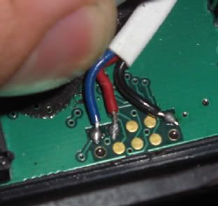
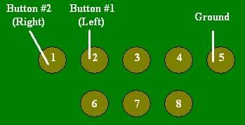
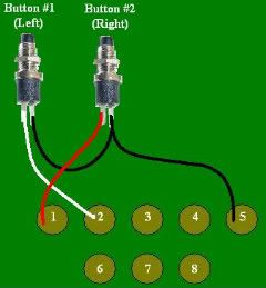
The way the buttons work is when they are pressed they connect to ground. If you look on the top of the circuit board there are a bunch of copper dots. I�ll explain this in words first and then also put a picture up that will clear it up. Numbering the dots from left to right, starting in the top left: 1 and bottom right: 8. Button 1 is pin 2, Button 2 is pin 1, and ground is pin 5. So connect one side of your #1 button to pin 2 and connect one side of your button#2 to pin 1 and then connect the other sides to each other and then to pin 5. When soldering make it fast your soldering times should be NO longer then 2 seconds. Put a little bead on pins 1,2,5 and solder the tips of the wire; then place the wire on top of the bead and heat the wire onto the board. You should solder as fast as possible to ensure that you do not mess with any of QTP�s internal circuitry.
Here are some drawings to clear that up:
Display:
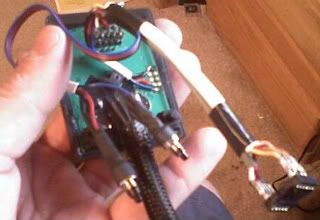
Next is the display, because it is no longer mounted directly to the board we are going to need to make an extension. The way that I made was similar to an extension cord one side is male that plugs into the board and the other is female that the LCD plugs into. There is not really a way for me to walk you through this� so I will explain how to make the ends and then you�ll have to look at my pictures and piece the rest together.
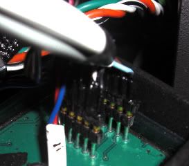
Let�s start with the side that will plug into the board. For this part we are going to use the �male to male DIP Socket� depending on what size you got you may need to cut it down we are only going to need an 11pin socket meaning there is 6 across the top and 5 across the bottom. To make this project a lot easier you should choose a 12 conductor wire that is flexible. Start by stripping back the wires and then soldering them to the DIP Socket. When soldering record the wire�s color and position so that you don�t mix up the signals. Do not put the pins into the circuit board to �hold them� while you solder. Just like earlier we don�t want to mess with QTP�s internal circuitry. Use one of those 3rd hand clamp things to help hold parts while you solder. I decided that it would be way to hard to shrinkwrap each one of the 11 conductors so instead when I was done I coated the connector in liquid electrical tape to ensure that none of the pins would touch each other during operation.
Here is a picture of the male side of my extension:
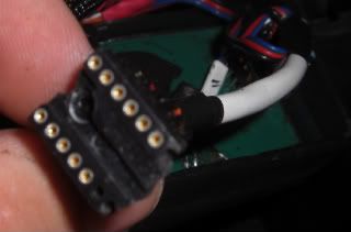
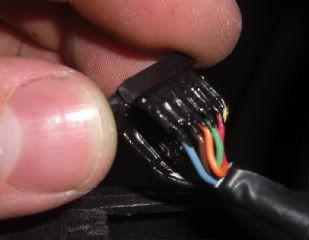
Now lets work on the female side that will connect to the LCD display that we superglued to the plexiglass earlier. Before you get ahead of yourself it may be a good idea to see how much wire you�re going to need to reach the LCD, you don�t want to be short and not reach and you don�t want extra wire all bundled up behind the dash. For the female part we are going to use the DIP socket. Again we need an 11pin socket with 6 across the top and 5 across the bottom. In a similar method to the male side we need to match up the proper pins with the proper colors this is why we recorded the colors earlier
Just like before we don�t want to attach the LCD into the plug to help �hold it� while we solder, have someone help hold it, or just get real mad then walk away and come back later to finish Below are some pictures of my female end:
Here is a picture of my finished controller with the extension and the buttons:
Step 7: Assembly
Finally the LAST section!!!
Now that you have done all this work it is finally time to put it all together!
I used Velcro to hold the controller to the cubby, and then next it is time to connect the LCD extension. First attach the female side to the LCD, be VERY careful with the pins they are small and very weak. Make sure that you get it to connect to all 11 of the pins on the display. Once that is connected you may need to carefully hold it together while you plug the male side into the controller.
Next is the buttons, push the buttons through the holes and thread on their nuts, be gentle here because as the nut spins it�s going to want to take the paint with it.
Last but not least if you added additional toggle switches like I did you will want to wire those up as well.
THAT�S IT!!! YOU�RE DONE!!
Here is a picture if my controller all wired up and ready to go:
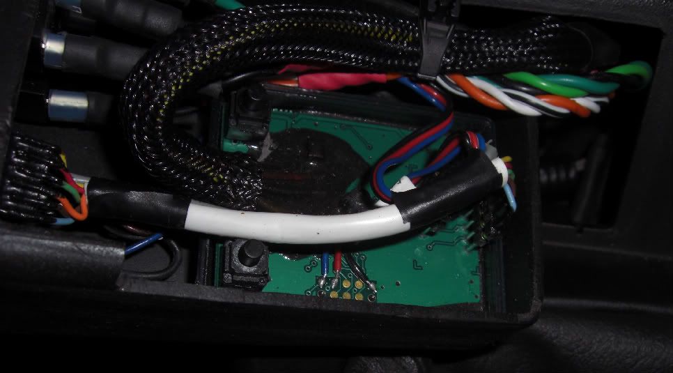
I hope this helps some of you guys out there who have cutouts, with the toggle switch or even the controller. I really didn�t want to mount the controller to my dash and couldn�t find a spot for it so I had to improvise and this is what I came up with. Let me know what you guys think!
Hope you like the write up.-CoryF
.
 08-30-2008, 09:43 AM
#4
TECH Senior Member
iTrader: (42)
Join Date: Dec 2004
Location: Tomball/Nacogdoches TX
Posts: 5,064
Likes: 0
Received 0 Likes
on
0 Posts
Interesting. I have a DMH electric cut-out and it opens and closes probably twice as fast as your qtp. I wonder if the module would work for DMH?
08-30-2008, 12:01 PM
#5
Teching In
Thread Starter
iTrader: (1)
Join Date: Sep 2007
Location: Tucson, AZ
Posts: 14
Likes: 0
Received 0 Likes
on
0 Posts
-CoryF
.