LS1/LS2/LS6 intake swap Sticky!!!
 04-13-2013, 07:07 PM
#141
Okay now I'm confused. I'm just trying to adapt this so-called write-up (yes David, it's pretty bad) for the LS2.
On the LS1/LS6 intake manifolds, there are three vacuum fittings, correct?
Could someone possibly provide the appropriate labels because it looks like the LS4 has three as well; one on top (PCV) and two on the right side (labels?). I also noticed that there's one on the LS4 throttle body.
You don't mind picking that up again? It's a great idea. Add that to the fact that the newer DoD/AFM VLOM trays are thinner than the ones on our cars, that the LS2 throttle body actually works, and that the LS4 fuel rail fits the LS2 intake manifold with some spacers, and you can see where this actually might be a better swap.
On the LS1/LS6 intake manifolds, there are three vacuum fittings, correct?
- One on the rear which also doubles for the MAP sensor.
- One on the left side (gets ground down and patched to clear the OPSU).
- One on the right side.
Could someone possibly provide the appropriate labels because it looks like the LS4 has three as well; one on top (PCV) and two on the right side (labels?). I also noticed that there's one on the LS4 throttle body.
You don't mind picking that up again? It's a great idea. Add that to the fact that the newer DoD/AFM VLOM trays are thinner than the ones on our cars, that the LS2 throttle body actually works, and that the LS4 fuel rail fits the LS2 intake manifold with some spacers, and you can see where this actually might be a better swap.
 04-13-2013, 08:32 PM
#142
TECH Fanatic
iTrader: (3)
Join Date: Aug 2009
Location: Orlando, FL
Posts: 1,392
Likes: 0
Received 0 Likes
on
0 Posts
Okay thanks.
What's the fitting on the right hand side? Basically, the fitting on the opposite side of the "PCV System Vacuum" in the following picture.

fieroguru?
What's the fitting on the right hand side? Basically, the fitting on the opposite side of the "PCV System Vacuum" in the following picture.
fieroguru?
04-13-2013, 09:37 PM
#144
TECH Fanatic
iTrader: (3)
Join Date: Aug 2009
Location: Orlando, FL
Posts: 1,392
Likes: 0
Received 0 Likes
on
0 Posts
So is it okay to assume that the LS4 throttle body's fitting is used for the EVAP? (not the PCV since that's at the top of the LS4 intake manifold)
The brake booster vacuum is to the right of the LS4 intake manifold. Add that to the fitting on the LS4 throttle body (EVAP?), and the PCV on top and that makes three vacuum connectons.
As per the following picture in David's write-up, the large hose is for the brake booster (LS4 OEM location) but was moved there and the hole widened on the LS1/LS6 intake since theirs is in the rear; he left the MAP back there though. He then drilled and tapped another hole in the throttle body adapter for the PCV. Then there's the third vacuum fitting that he didn't have to touch since he's using the LS4 throttle body.
So that brings me back to the LS2. Would a throttle body spacer be needed so that a third vacuum hole could be made? Because as it stands, the left side fitting would need to be blocked off due to the OPSU. The rear will need to be blocked off and relocated since it has fitment issues with the accessory belt. So that's two fitments needing "homes" and no "homes" available.
Does the LS2 throttle body have a fitment?
Assuming that a throttle body spacer gets used, then I guess each side could be drilled and tapped. Ideally, such a spacer would be angled upward. Dom87SS? *nudge* *nudge*
04-13-2013, 09:38 PM
#145

The end has 2 fittings one large (brake booster), one very small for a vacuum line. Off the throttle body the one with the traditional barb is likely for the PCV (dirty air return) and the other side uses a quick disconnect and probably goes to the evap.
On my swap I cut and capped the two at the end. Used the barbed fitting at the neck for the brake booster and the quick disconnect side (used the LS4 disconnect fitting with the poly line removed and replaced with hose) for the PCV (not using the electronic evap).
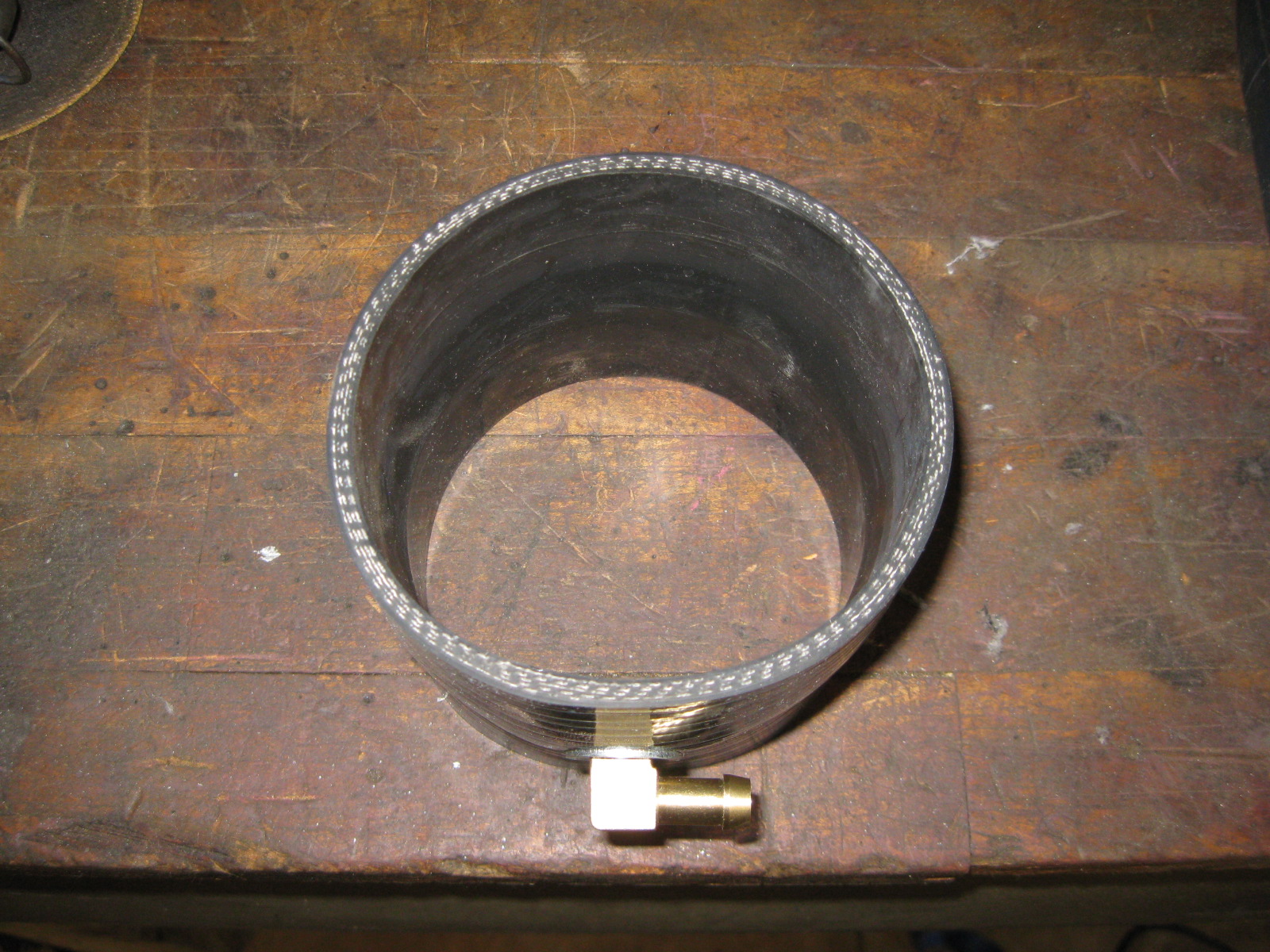
The challenge is the clean air for the PCV. The LS4 MAF/TB rubber coupler has this port molded into it, but it won't fit the LS2 TB. I drilled a silicone coupler and bolted in a brass nipple for my swap.
04-13-2013, 09:42 PM
#146
TECH Fanatic
iTrader: (3)
Join Date: Aug 2009
Location: Orlando, FL
Posts: 1,392
Likes: 0
Received 0 Likes
on
0 Posts
Thank you very much. Do you happen to have any pictures?
All I see are three fittings: one nipple at the rear (brake booster) and the two up front (one on each side).
All I see are three fittings: one nipple at the rear (brake booster) and the two up front (one on each side).
04-14-2013, 07:21 AM
#147
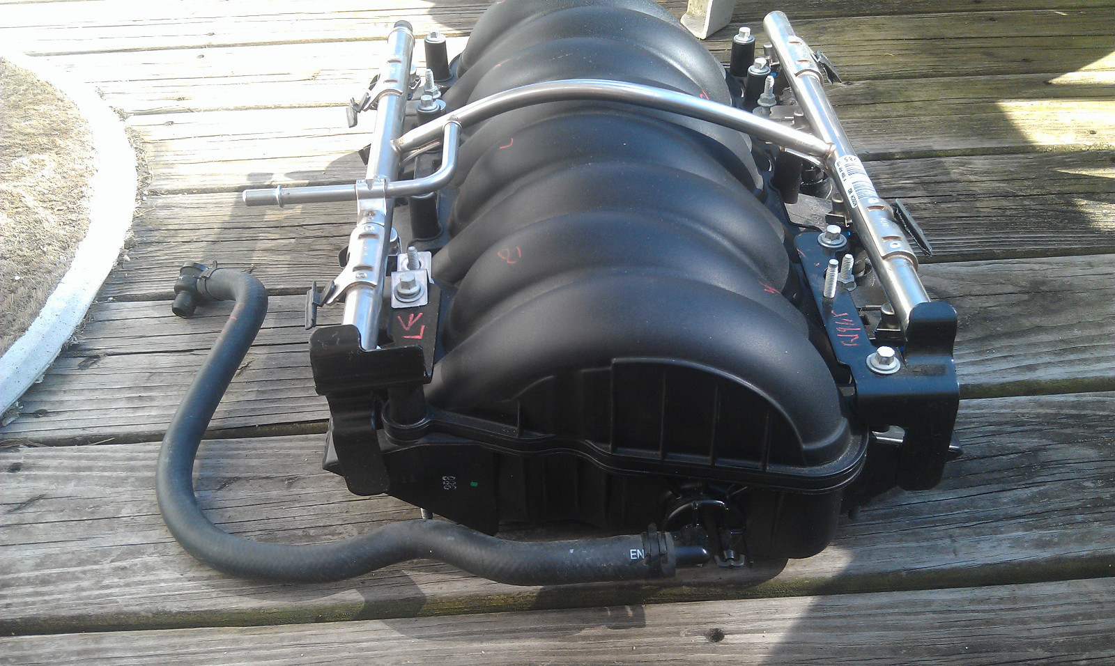
Here is you can see the two holes I plugged on the end (Notice my water pump has the power steering bracket removed... not sure if these nipples would clear with the stock PS pump). Maybe there are multiple styles of car LS2 intakes, some with 3 nipples and some with 4.
Here is a picture showing both ports before cut (stole from an ebay listing):
Here is the LS4 throttle body and intake tube showing the 2 nipples. The one on the throttle body goes to the evap purge solenoid, the one on the intake tube is the clean air for the for the PCV. The LS2 throttle body does not have any vacuum ports:
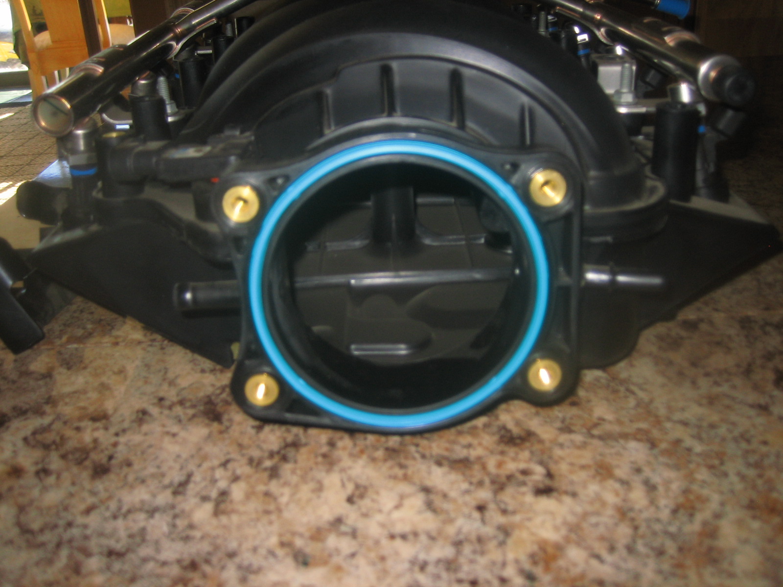
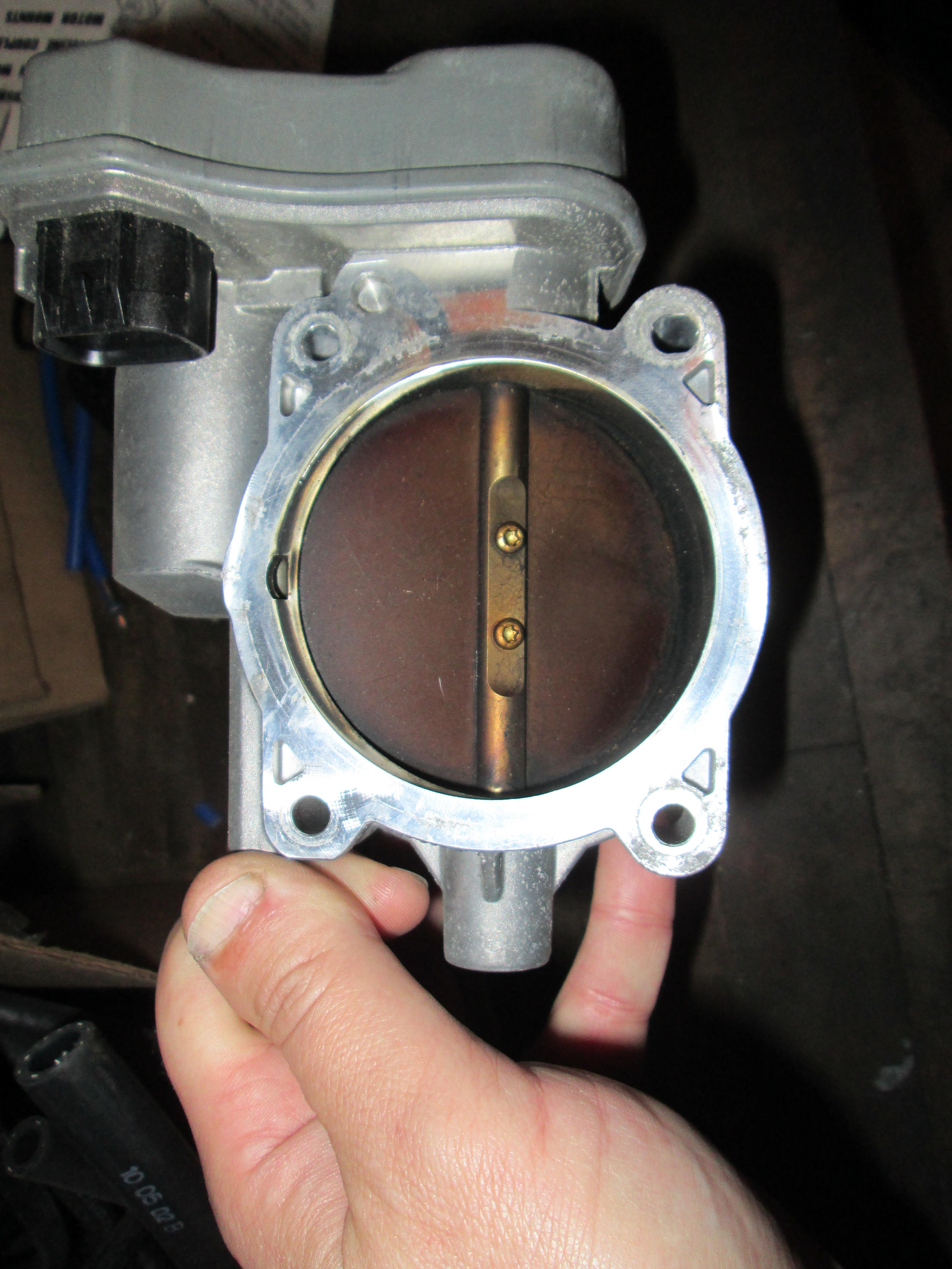
Here you can see the vacuum port right above the throttle blade:
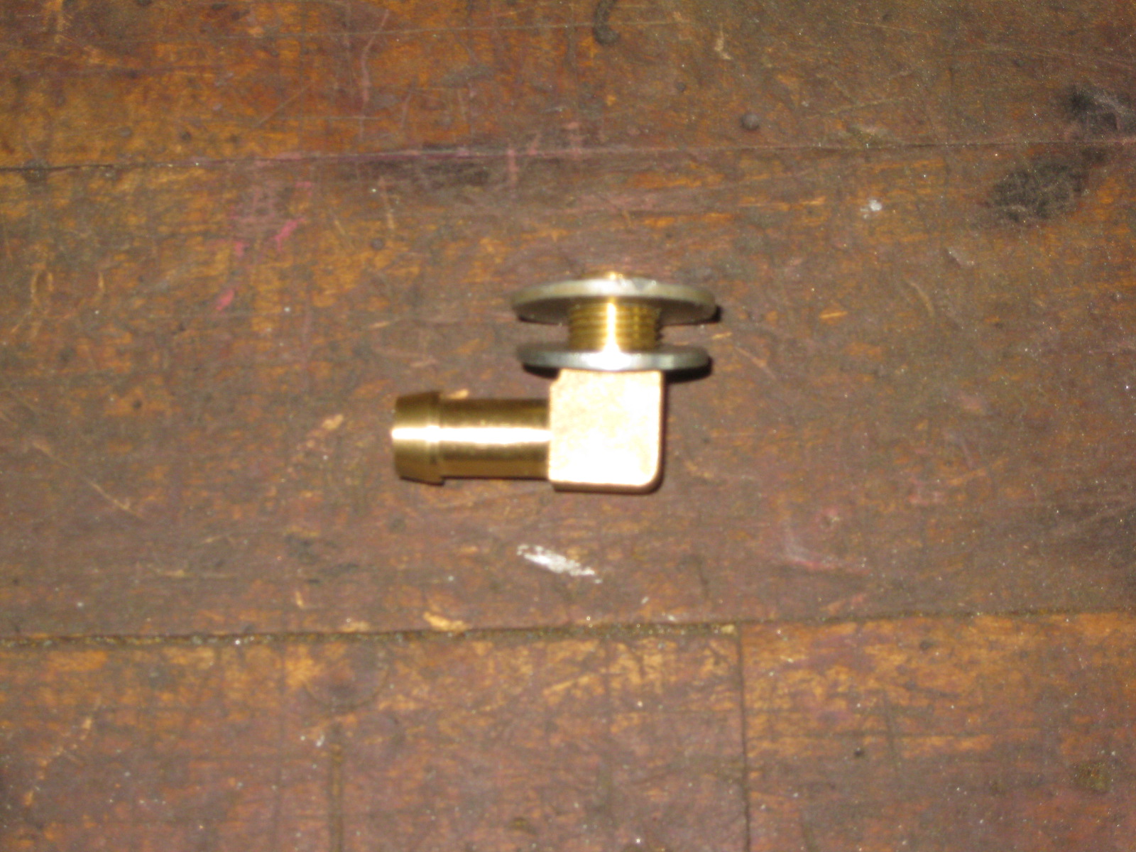
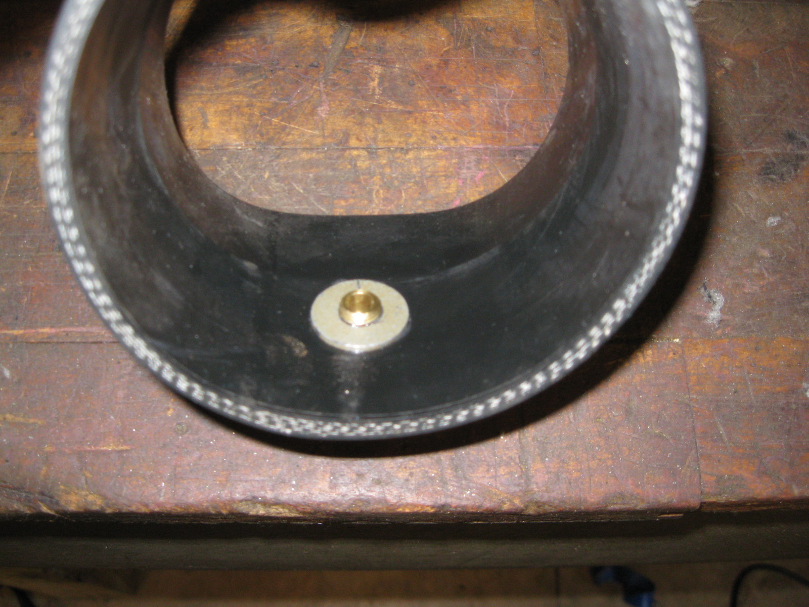
For my swap I added a nipple to the silicone coupler for the PCV. I took a brass 90, found a washer that slide over it, then another one that didn't. I threaded the one with the smaller ID so it became a low profile nut. Then when I assembled it, I used silicone on the washer faces and locktite on the threads to keep it from coming loose and being ingested.
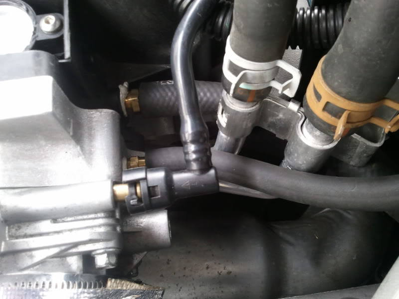
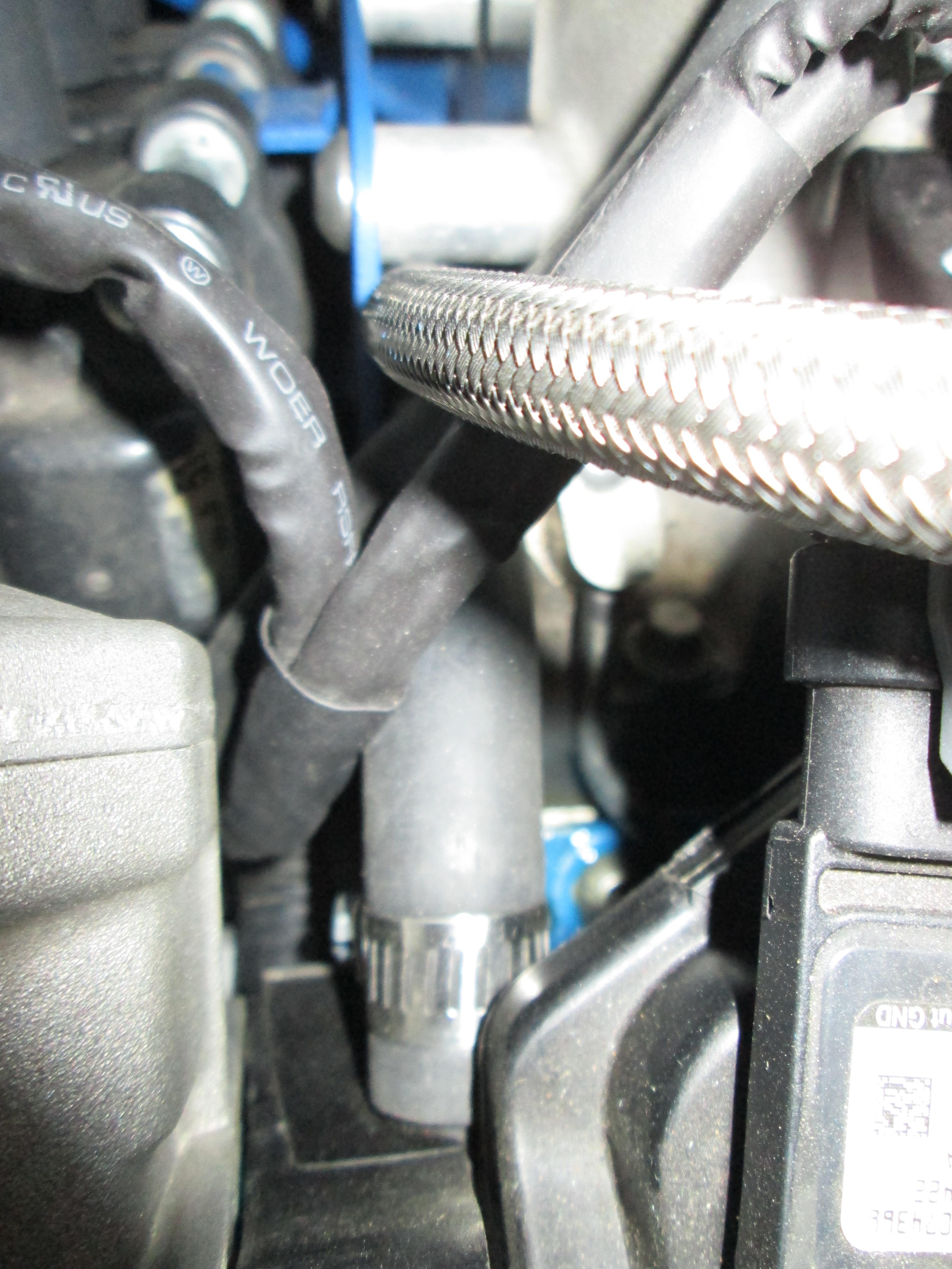
Here is where I used the LS4 nipple quick disconnect (from the evap system I assume) and added a rubber hose to it for the dirty side of the PCV or the return from the catch can):
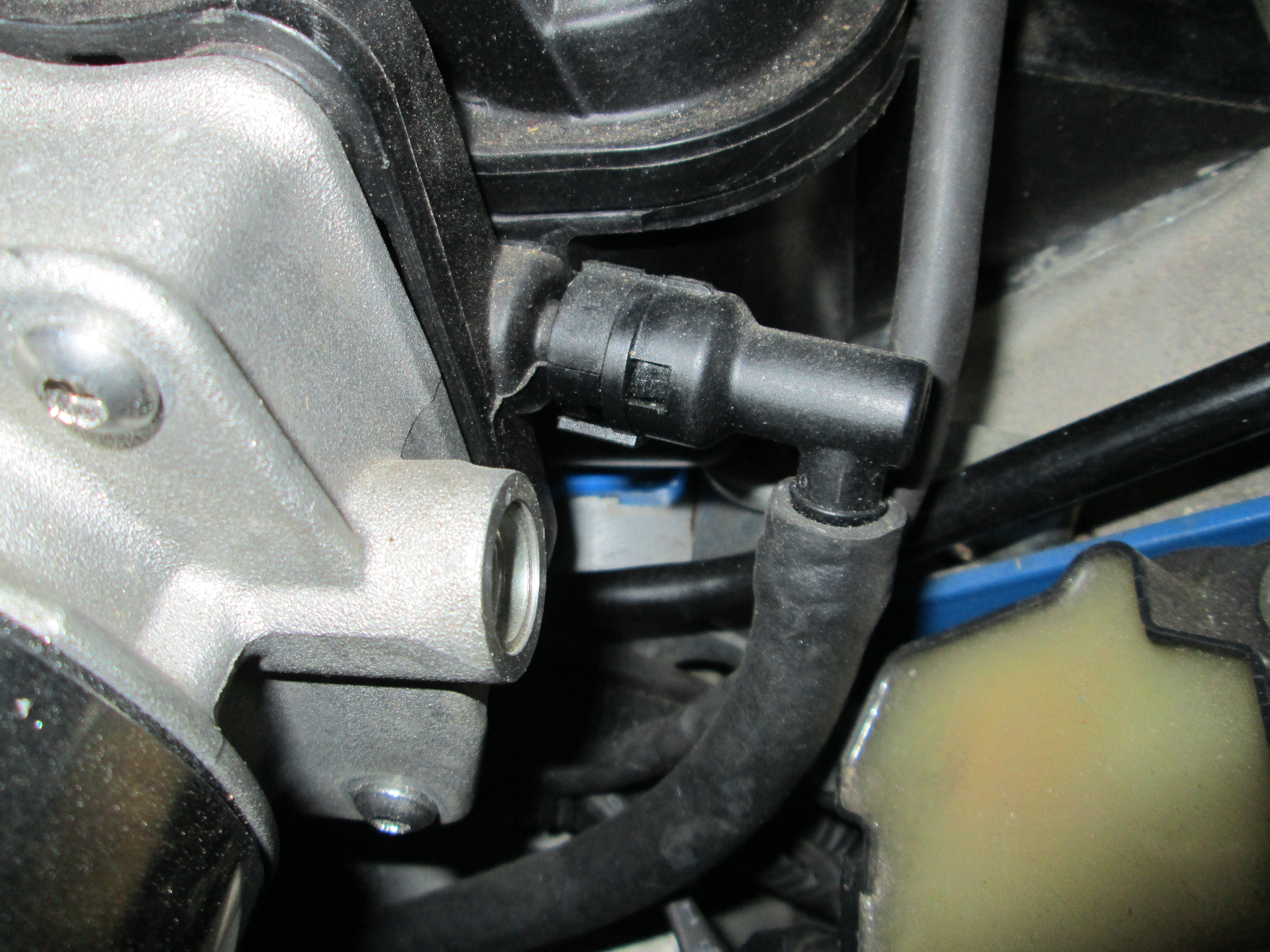
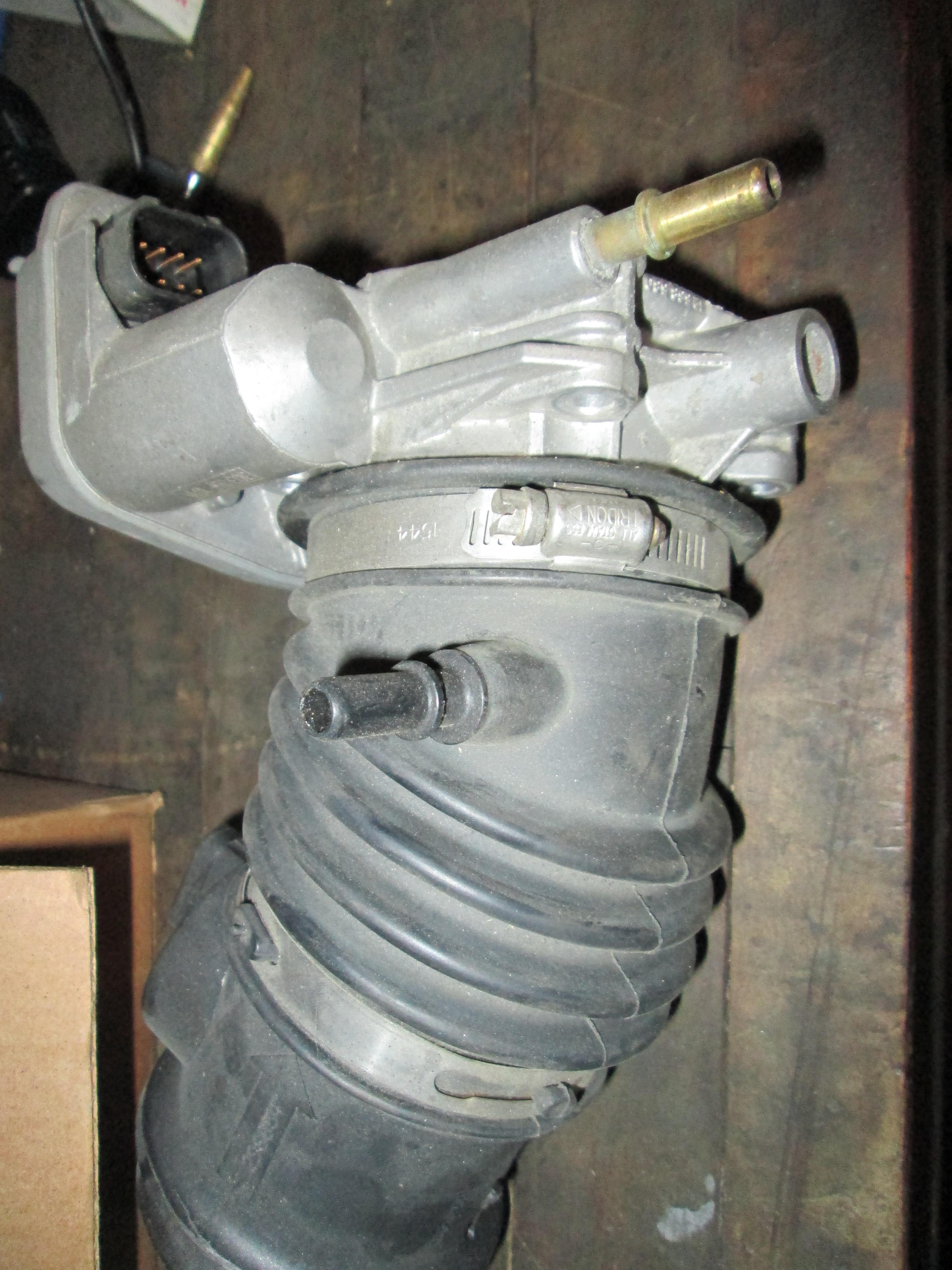
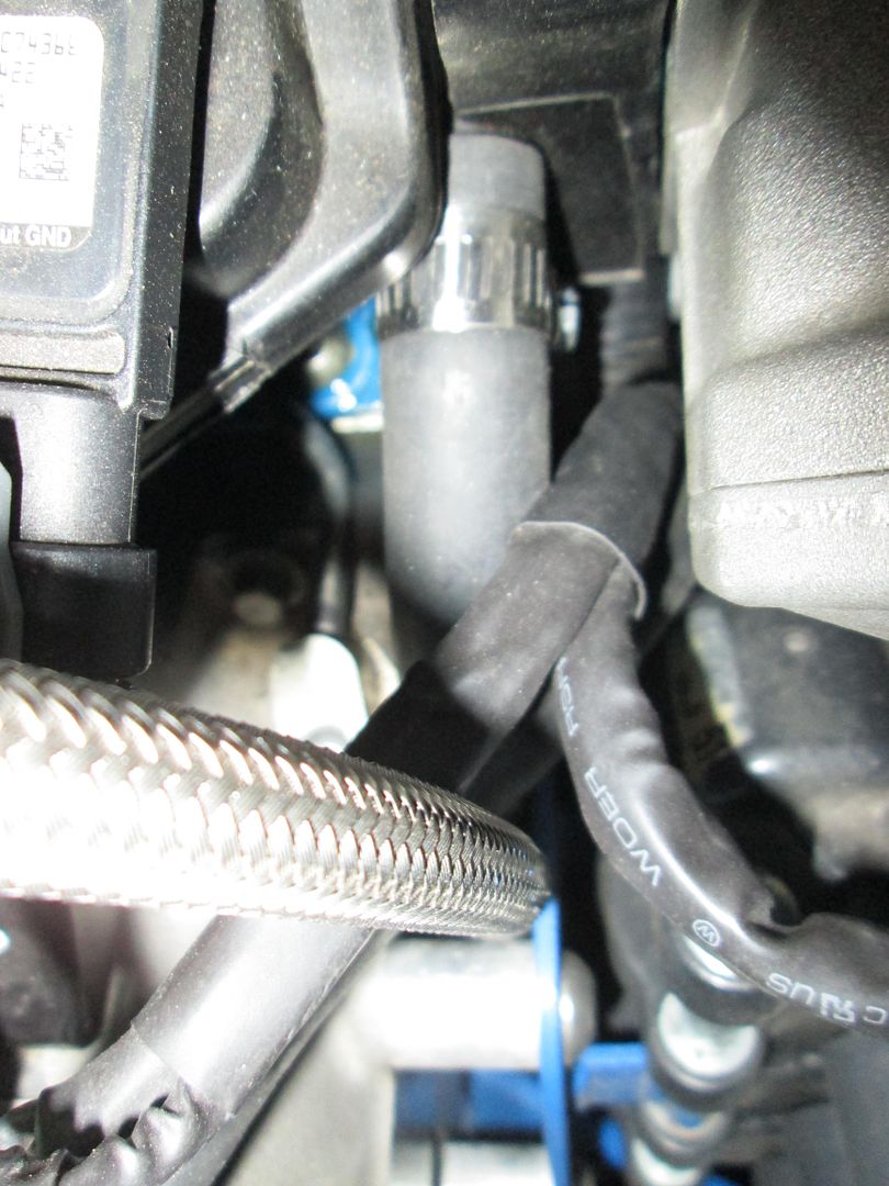
It is hard to see in this picture but this is the brake booster connection (with the hose clamp) to the barb nipple opposite from the quick disconnect nipple. This nipple wasn't large enough in OD for the booster hose, so I built it up with a few layers of electrical wire heat shrink.
Also, the MAP sensor on the E67 LS4's (or at least mine) didn't fit the LS2 intake, so I purchased an LS2 MAP sensor and pigtail. If you swap MAP sensors, you need to change the values in the calibration as they are calibrated different and you will set a MAP sensor code for the sensor being out of range. I originally though it was due to the 224/232 camshaft, but after some research I found it was a common issue with MAP sensors being calibrated differently across the various intakes.
McMaster.com part # 92510A801 are aluminum spacers 5/8" in length, 3/4" OD and with a 5/16" hole. These work great to mount the LS4 fuel rail to the LS2 intake and cost $2.30 each or less than $10 + shipping. Then you can either run the LS4 injectors with the injector spacers or the longer LS2 injectors w/o spacers.
Here is a picture showing both ports before cut (stole from an ebay listing):
Here is the LS4 throttle body and intake tube showing the 2 nipples. The one on the throttle body goes to the evap purge solenoid, the one on the intake tube is the clean air for the for the PCV. The LS2 throttle body does not have any vacuum ports:
Here you can see the vacuum port right above the throttle blade:
For my swap I added a nipple to the silicone coupler for the PCV. I took a brass 90, found a washer that slide over it, then another one that didn't. I threaded the one with the smaller ID so it became a low profile nut. Then when I assembled it, I used silicone on the washer faces and locktite on the threads to keep it from coming loose and being ingested.
Here is where I used the LS4 nipple quick disconnect (from the evap system I assume) and added a rubber hose to it for the dirty side of the PCV or the return from the catch can):
It is hard to see in this picture but this is the brake booster connection (with the hose clamp) to the barb nipple opposite from the quick disconnect nipple. This nipple wasn't large enough in OD for the booster hose, so I built it up with a few layers of electrical wire heat shrink.
Also, the MAP sensor on the E67 LS4's (or at least mine) didn't fit the LS2 intake, so I purchased an LS2 MAP sensor and pigtail. If you swap MAP sensors, you need to change the values in the calibration as they are calibrated different and you will set a MAP sensor code for the sensor being out of range. I originally though it was due to the 224/232 camshaft, but after some research I found it was a common issue with MAP sensors being calibrated differently across the various intakes.
McMaster.com part # 92510A801 are aluminum spacers 5/8" in length, 3/4" OD and with a 5/16" hole. These work great to mount the LS4 fuel rail to the LS2 intake and cost $2.30 each or less than $10 + shipping. Then you can either run the LS4 injectors with the injector spacers or the longer LS2 injectors w/o spacers.
Last edited by fieroguru; 04-14-2013 at 07:41 AM.
04-14-2013, 07:30 AM
#148
TECH Fanatic
iTrader: (3)
Join Date: Aug 2009
Location: Orlando, FL
Posts: 1,392
Likes: 0
Received 0 Likes
on
0 Posts
Thanks for those pictures!
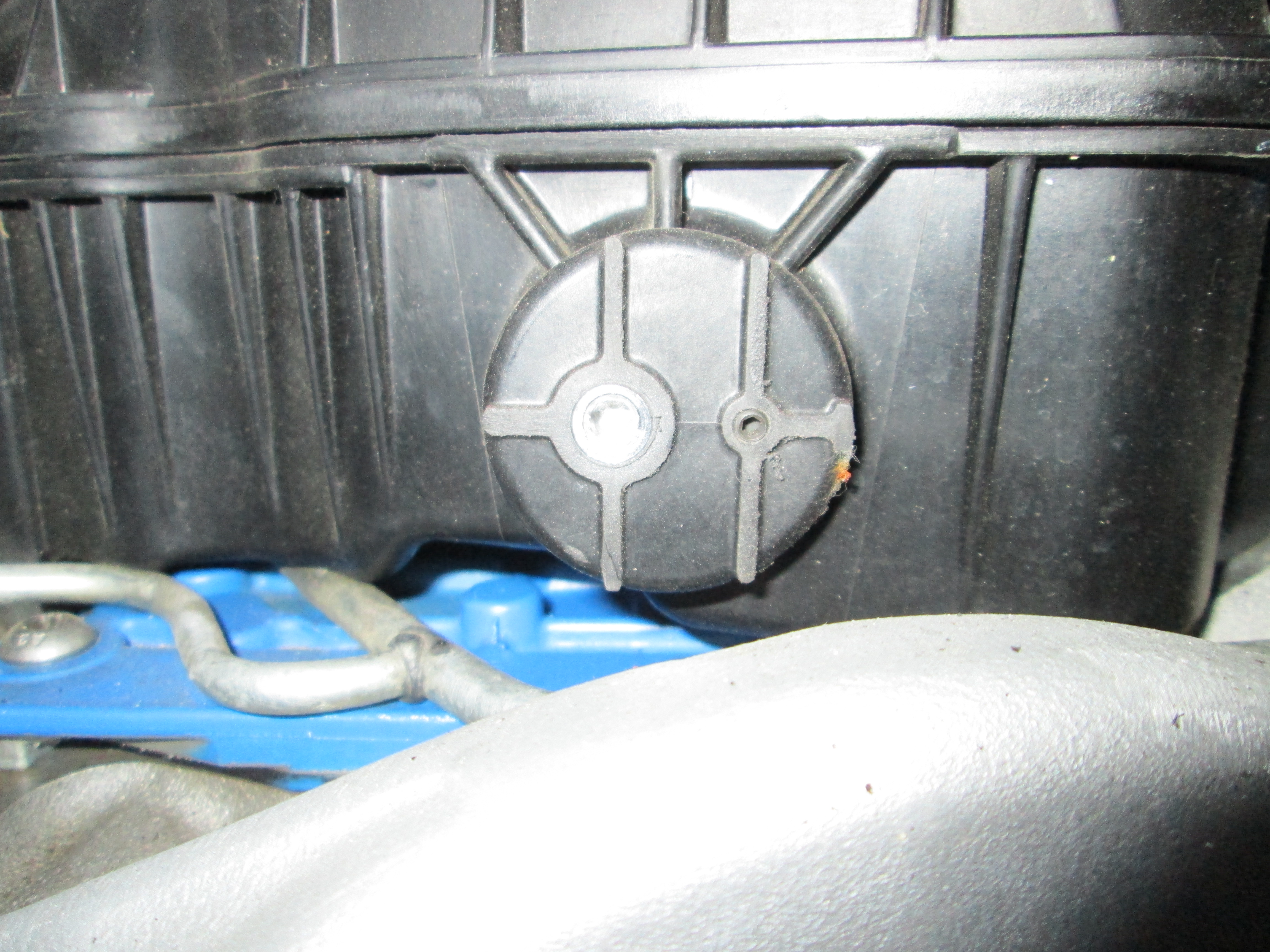
I was going to post the following picture showing the fourth vacuum line which is actually sealed with a T-shaped cap. But good thing you replied.

I was going to post the following picture showing the fourth vacuum line which is actually sealed with a T-shaped cap. But good thing you replied.
04-14-2013, 09:20 AM
#150
TECH Fanatic
iTrader: (3)
Join Date: Aug 2009
Location: Orlando, FL
Posts: 1,392
Likes: 0
Received 0 Likes
on
0 Posts
It is hard to see in this picture but this is the brake booster connection (with the hose clamp) to the barb nipple opposite from the quick disconnect nipple. This nipple wasn't large enough in OD for the booster hose, so I built it up with a few layers of electrical wire heat shrink.
Here's a [nasty] drawing I made in paint outlining the swap. Of course, you would need to grind down the OPSU and weld it at an angle along with modifying the DoD/AFM connector.
With the thinner DoD/AFM VLOMs out there, hopefully the intake fits. Or maybe someone can get those intake spacers going it might even be a better fit.
04-14-2013, 09:42 AM
#151
TECH Fanatic
iTrader: (3)
Join Date: Aug 2009
Location: Orlando, FL
Posts: 1,392
Likes: 0
Received 0 Likes
on
0 Posts
McMaster.com part # 92510A801 are aluminum spacers 5/8" in length, 3/4" OD and with a 5/16" hole. These work great to mount the LS4 fuel rail to the LS2 intake and cost $2.30 each or less than $10 + shipping. Then you can either run the LS4 injectors with the injector spacers or the longer LS2 injectors w/o spacers.
EDIT: It looks like the OEM bolt studs are long enough.
Last edited by GXP25; 04-14-2013 at 04:10 PM. Reason: Added some more info.
05-04-2013, 08:01 PM
#155
**** my life **** gm **** this car OK down ranting almost done with the swap ended up slicing the alternator bracket on the car to much of a pain in the *** to take off broke the spare dod conmector trying to solder it so oh well its like I use dod anyway and the damn heater lines hit the throttle body adapter so have to grind the corner off an unbolt the heater hose lines to bend them down out the way I'll post pics later and a video of what David Gxp was saying about the fuel limes pivoting over
BTW there is no need to buy any kind of extension harness all you need to do is pull the wires from the loom there is more than enough there to support any location on the manifold
BTW there is no need to buy any kind of extension harness all you need to do is pull the wires from the loom there is more than enough there to support any location on the manifold
Last edited by 91parkave; 05-05-2013 at 12:46 AM.
05-15-2013, 08:53 PM
#157
12 Second Club
iTrader: (3)

Join Date: Feb 2011
Location: S. FL to Philly ??
Posts: 382
Likes: 0
Received 0 Likes
on
0 Posts

The fuel line pivot in case anyone wanted to know is in the video I made
Moving stock ls4 fuel line over to lsx fuel rail - YouTube
Moving stock ls4 fuel line over to lsx fuel rail - YouTube
Cheers
05-15-2013, 09:03 PM
#158
First start up was flawless however I ran into some minor bugs with the ls2 tb blade getting stuck causing a reduced power mode the fuel rail inlet I heated up and used a tubing bender to move it up and to the right just slightly to clear the coil pack everything else was smooth and if you have the means to do so I'd recommend cutting the alternator bracket on the car just be careful to lay a towel or something to cover everything else from sparks and debris. And you might have to grind the back right portion of the manifold to clear the coolant crossover and grind the back left webbing between the intake bolt hole and intake so that bastard power steering line can easily clear it.
05-16-2013, 09:29 AM
#159
TECH Apprentice
iTrader: (3)

Join Date: Mar 2005
Location: Mchenry, IL
Posts: 349
Likes: 0
Received 0 Likes
on
0 Posts
I had a little stumble along the way of getting mine installed but the new part is now done. The guys at my work were a little concerned with the previous material I had used to make the TB adapter in that over time it may sag which would obviously cause a huge vacuum leak. So I modified the file a little added more thickness to it, added larger radius edges for strength and then made it in a high temp material. This stuff has a heat deflection of 335 F and we decided since its being used for air flow we tumble polished the part to smooth it all out then coated it with a high temp (350F) epoxy to seal it up and give it a super smooth finish. So Im back on track to get this done. Im going to be busy the next few weekends doing automotive photoshoots and drag race coverage (my side gig  ) then ill be able to jump on this. Im really excited to get this and few other items on the car to wake it up.


) then ill be able to jump on this. Im really excited to get this and few other items on the car to wake it up.