When you click on links to various merchants on this site and make a purchase, this can result in this site earning a commission. Affiliate programs and affiliations include, but are not limited to, the eBay Partner Network.
Pull the rubber hose off while the engine is running and you will find that a steady stream of water comes out the end. They are called steam lines, but water flows through them when the thermostat is closed and takes any air bubbles with it. On a running engine air can not be trapped within the lines - regardless of elevation difference to the inlet of the radiator.
I need to see another pic then; so far these things look like they are all interconnected with no other in/outlet or bleed point. I just don't know how I'd get the air out in the first place unless this ***'y is flat (looks like it might be) and the whole thing is lower at their points of connection than something else in the head/manifold/other?
Again I need to get my motor (maybe tomorrow?) to really see; I'm still very much in learning mode.
as fieroguru states " with the thermostat closed and liquid moving" this is a fact. What I do not agree on is "just connect from the spigot in the pic to the radiator return line."
Reason:
It should be connected to a proper resivoir as any air, not only initial air but air that does find its way in over time (LS4 water pumps for example) it can actually exit a closed system hot and then draw back/replenish itself with coolant during the cool down.
re: Pic from fieroguru;
for some reason the pic gets distorted badly when I try to copy;
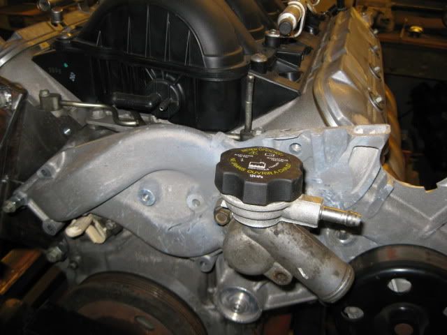
I think the vent outlet tube is the vertical one just behind and very slightly left of the black cap in the foreground. This wasn't showing up (or I wasn't looking hard enough?) in other pix so I"ll double check. Yes, if there, then this gives me the venting I was concerned about.
When the thermostat opens, it will send a high volume of coolant through the radiator return line to help move any air pockets to the radiator where it can be purged.
At start-up after the coolant system has been open, what I do is pull the vent hose while the engine runs and let all the air out. Once I have a steady stream of coolant, I slide the hose back onto the radiator return line. This eliminated 90+% of any air in the engine block and immediately purges it from the coolant system.
With the Fiero application, the radiator is at the other end of the car, so both radiator hoses drop down to about 6" off the ground, travel the length of the passenger compartment and then raise back up to connect to the radiator. The only air purge in the system is at the radiator over flow and many fiero swaps have cooling issues if they try to add in a secondary air purge in the rear as the front will then tend to suck air back into the system. To effectively run a rear air purge system, the front purge at the radiator must be 100% disabled, but doing so just adds more stuff in the engine bay to distract from the overall visual appeal of the engine. Using the stock Fiero air purge setup works well, so why mess with it.
In the stock W body config, the steam tubes dump to the top of the water pump (no significant coolant flow) where there is another hose that connects to the pressurized expansion tank that also serves as the air evacuation tank.
re: Pic from fieroguru;
for some reason the pic gets distorted badly when I try to copy;
I think the vent outlet tube is the vertical one just behind and very slightly left of the black cap in the foreground. This wasn't showing up (or I wasn't looking hard enough?) in other pix so I"ll double check. Yes, if there, then this gives me the venting I was concerned about.
Thx again guys and fieroguru for the pix.
GP
Yes the steam pipe is the vertical one behind the fill cap in the picture. What you do not get to see in that pic is there are 2 spigots on that fill tube neck/assembly... the aft one (is normally where the steam pipe/vent tube connects to) and the one pointing to the right/ front of car is to the reservoir/ overflow tank.
But as ferioguru states when used in different applications some thought and compromise will be required. You could use a reservoir up front in FG`s application but it would have to be mounted up front and the full cold level must be slightly higher than the highest point in the system and required plumbing all the way to the spigot in the rear of the car.
Last edited by Ill_Born_ss; 10-25-2014 at 08:30 AM.
You could use a reservoir up front in FG`s application but it would have to be mounted up front and the full cold level must be slightly higher than the highest point in the system and required plumbing all the way to the spigot in the rear of the car.
Elevation of the expansion tank doesn't matter if its a non-pressurized version (like the stock Fiero overflow tank). Coolant pressure will fill it, and as the system cools it will siphon the coolant from the bottom of the tank... even if its lower than the coolant level in the radiator, which is several inches lower than the coolant in the engine.
If you have a pressurized expansion tank (OEM in the W-body), then it does need to be at or higher than the coolant level in the rest of the components as there is no relative pressure difference between the parts. W/o any pressure difference, the coolant will seek a uniform level between the engine/radiator/expansion tank.
Well the learning process will accelerate now; the new project is in the garage (!) and on the engine stand and partly dissembled.
A few things: this is from an 07 Monte. I see the OPSU is a bit different from others I have seen in various threads; and there is something else 'beside it' where the OPSU used to be? It appears to be sensing just oil pressure; the connector is 3 pin. It isn't connected to the solenoids under the pan. Nice, flat OPSU connector! But what is that other (tall) one doing?
and
There is a sensor at the bottom of the oil pan; no idea what it is yet; visible from the right side and at the very bottom. Any guesses/input? The wires are (or looked like) black w/white stripe and black only.
And this thing was lying on top of the engine; no idea what it is or if it is even part of this engine?
Had a tough time getting the harmonic balancer BOLT out, forget the balancer itself - yet to come off... I don't know if I need a special tool to get this one off but will find out soon!
The adventure continues! Very different engine from the ole SBC! Now I see what people were talking about; DoD defeat etc.
Tiny oil filter! wow! Looks like a knock sensor each side; evidence of manual grinding/routering on the bottom front of the valley casting of the engine (oil return assist?) i have a steam vent line at the front (balancer end) two connections but the back two are plugged.. valvetrain/rockers were clean so somebody changed their oil. Good..
I see I have to remove the rocker ***'y to get the head bolts OUT; got one head off without doing this but will get there. Need to find out what the aftermarket trunnion supports are for and how they install....
Interesting 'fins' leading down into the lifter bores. Wonder what that is all about? Sure look like cooling fins! But to give up heat to 'captive' air? Doesn't make sense..
Underside of DoD valley pan. Wonder if this is typical?
So quite pleased; the engine turned over well and was clean inside despite the hint of black crap on the dipstick; the underside of the valve covers were nice and clean. Great indicator.
I just realized I don't have a wiring diagram; I will be running an E67 ECM so the pinouts/ECM diagrams should be for that if anyone has a source.. much appreciated in advance.
The plan:
hone and new rings;
micro polish crank and rod journals;
new bearings - bottom end;
New main seals;
New gaskets throughout;
Port and polish the heads; (expected to be very labour intensive....)
New fairly aggressive cam;
defeat DoD; all new conventional lifters;
New LS2 timing set;
Retain stock rockers;
new springs, keepers, retainers;
LS6 intake (have it - ported aftermarket)
New LS7 exh manifolds (have them)
LS6 TB DBW (have it)
85mm MAF (have it; non-screen type)
LS6 injectors (have them)
LS6 fuel rail
new oil pump
new water pump
shorter accessory belt (a la fieroguru)
no EGR (don't need to pass emissions)
Reprogrammed e67 ECM;
connect to F40 6 spd manual (have it)
install in fiero..
make it run!
;-)
The bolt will come out. Just use a vice grip and a long breaker bar. For the balancer itself go grab a Chrysler 3 jaw puller from Autozone and it'll come right off.
For the sensors yours is just like all the others. The 3 pin is the opsu the 5pin is the DOD solenoid sensor
The sensor on the bottom of the oil pan is for the oil level
There's no way it was going to come out with vice grips.. I had to put a piece of flat bar between two flywheel bolts then a 4 ft pipe on my breaker bar with the socket.... and it finally 'pranged' free.... the impact gun didn't even touch it!
Thx for the tip on the Chrysler puller. Hopefully I can borrow one for this one-timer.
Will need to figure out a balancer installer for the other end of this work.
Guess I was thinking that the OPSU sensed pressure AND controlled the solenoids; all with 5 wires. I thought the OPSU was the taller thing that had to be cut down; on mine it is already short. Doesn't matter; it will be eliminated and the oil pressure sensor moved elsewhere. I guess I'll tap and plug the hole that it is in; there is of course a matching hole from the crankcase up to it, so that has to be covered off.
Busy today so no more progress till tomorrow, but need to start looking for wiring diagrams for the E67; pinouts etc. Any leads, anyone?
Wonder if there is any market for LS4 stock engine parts?
Guess I'm going to find out!
Will be interested in finding out the max lift cam that will still work with std stock lifters - if there is a limit anyway?
If I order a new oil pump, which will have the higher pressure (if there is a difference) the LS6 or the LS2?
The hardest part about removing the balancer bolt is keeping the engine from turning and keeping it from tipping over (it 200+ ft lbs). I used a piece of ring gear in the starter pocket when the engine/transmission are still together, but you can also use some c-clamps to hold it in place as well. Use the longest/strongest cheater bar and get a friend to help stabilize the engine (might bolt a long piece of steel to the bellhousing holes to they can keep it from turning/tipping).
The OPSU is the same as all the others, you just still have the connector end (wires ripped our) on it. The DoD connector looks stock as well, may of the pictures posted are after they are modified to fit under a different intake manifold.
The solenoid from the top of the intake is the EVAP purge (I didn't use it on mine - no emissions testing).
The sensor on the bottom of the oil pan is the oil level sensor. I wired it up to the ecm vs. leaving a sensor w/o wire connection, but you have to have a BCM to get the oil level signal.
The Gen 4's have less of an issue with the needle bearings coming out of the rocker trunions, but if you want you can still upgrade them and get a stronger cross shaft (never heard of one breaking/wearing), then you can install this kit
#13702-KIT Rocker Arm Trunion Upgrade from Comp Cams
late response; I did a DOD on my ls4, let me know if you need anything. Do you still need a ls6 oil pump?
yes; I will need one; how much mileage on the one you have?
If you can send a pic to my email: gwpotts5@gmail.com that will be fastest for me; I only log on here from time to time.
I am also looking for a non-DoD valley pan; doing the DoD delete of course.
I can't post in the classified section till I have at least 50 posts elsewhere on the site and they can't be 'filler' posts .. as I have just found out, so I can't go there to ask for or respond to any ads...
50 posts. Going to be a lot of questions! Thanks in advance for your patience....
GP
 10-24-2014, 05:16 PM