
HOW TO: Make a Timing Retard Box for a Nitrous Oxide system...
 04-28-2012, 05:45 PM
#1
This mod is for those of you who want to retard the spark timing in your car while spraying nitrous but don’t want to give up that horsepower while on the street the other 99% of the time you aren’t spraying. Yeah you could buy a more expensive timing retard box that costs in the $275 range or you could do this mod for about $30. Your choice. I got the idea for this mod while tuning in my IAT Spark Tables for methanol injection spark advance. But like everything else, when I looked around online to see who else had thought of it of course somebody had already beat me to it so I guess I wasn’t the first with this bright idea. I notice that allot of people ask about these on here but not one has really posted a how to thread on what to do, so here you go.
Use this mod at your own risk. I will not be responsible for any wiring or tuning debacles you may put yourself in if you misuse the information in this post.
To understand how this mod works you need to first understand how the IATS (Intake Air Temperature Sensor) works and how it interacts with the ECU (Engine Control Module). Basically an IATS is just a thermally modified resistor (aka thermistor). At different temperatures that it encounters the sensor outputs a different electrical resistance (measured in ohms). The ECU outputs 5 volts on one wire leading to the IATS and measures the return voltage on the other wire coming from the IATS. The difference in voltage is in direct proportion to the amount of resistance the IATS causes but the ECU still needs to know how to interpret this. That is where the IATS Calibration Table comes into play that is in the ECU tune.
Here is an IATS Calibration Table from a 2009 Pontiac G8 GT. The tables for the GTO’s and other LSx vehicles look similar.

As you can see, different intake air temps are represented by differing resistance values. For the purpose of this modification we want to focus on the lowest temperature cell, which is -40*F in this case. Now we all know that short of a VERY few exceptions there is no one who will be driving their G8, GTO, or Corvette in -40*F weather so this cell is virtually useless for normal driving use. But we can use it for the purpose of retarding spark timing while spraying nitrous. Notice how the resistance value is 100,866 ohms. We will use that later in this writeup.
Now let’s move onto what the ECU does with this temperature data with regards to spark timing.
Below is your typical IAT Spark Adder Table. This one is from a 2009 Pontiac G8 GT but the ones in a GTO tune will look similar.
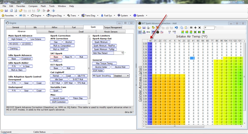
As you may have noticed, I have already modified the tune so that -4 degrees of spark is taken out at all cylinder loads in the -40*F cells in the IATS Table. Pretty simple, but there is one more item to change in the tune before you are finished.
Enter the IATS Spark Adder Multiplier Table. As always, this one is a G8 GT table but your GTO table will look similar, with a few small temperature cell differences.

This table will multiply whatever figures are present in the corresponding temperature cell of the IAT Spark Adder Table. In this case we know that we are requesting -4 degrees in the IAT Spark Adder Table across all cylinder loads. So at whatever RPM vs IAT cell I request a multiplier of 1.00 I will retard -4 degrees of spark advance out of the tune below what is already in the Base Hi/Lo Octane Spark Tables. If my multiplier is 0.50 then I will only be pulling -2 degrees at that RPM. Most people start spraying at around 3,000RPM’s so that is what this example is setup to represent. I like to feather spark changes in and out gradually to keep things smooth so that is why I am already requesting that 50% of the IAT Spark Retard be taken out in the 2,500RPM cell.
Now what we have accomplished is setting up the tune so that it only pulls spark advance when it senses -40 degree IAT’s and only from 2,500RPM’s on up. Yes the ECU will also interpret the cooler aircharge as a more dense one and will want to add a bit more fuel to compensate. But you will want to use a richer WOT AFR anyways, so that won’t really be a problem because you will be jetting your wet nitrous system to enrichen WOT AFR’s anyways.
Now onto making the Timing Retard Box.
First off is a list of parts that will be needed:
• Radio Shack plastic “Medium Small Project Box” x1
• Relay, 12VDC, 5 pin automotive relay x2 (<----Make sure these are 5 pin with pin #87a)
• Resistor 0.5 watt, 100k Ohm x1
• Resistor 0.5 watt, 5k Ohm x1
• Electrical Spade connectors, �” x 18gauge x10
• Relay Harness pigtails x2 (this is optional and would replace the 10 �” spade connectors above)
• Wire, 18gauge various colors x10’
• Solder
• Heat Shrink Tubing Small and Large sizes
• Grommet, Rubber roughly 3/16”-3/8” x1 (Size of grommet depends on size of wire you go with)
• Zip Ties, Small x5
Total Price: $30
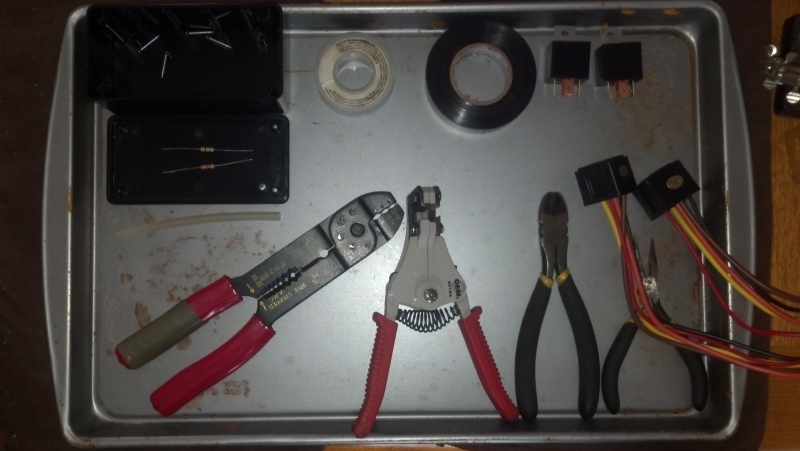
Tools Required:
• Basic Wiring Tools
• Digital Multimeter (<----Not 100% needed but helpful for testing resistance, voltage, and connectivity)
• Heat Gun or Hair Dryer
• Soldering Iron or Gun
• Drill and Drill bit
• Philips Screwdriver
Continued...
Use this mod at your own risk. I will not be responsible for any wiring or tuning debacles you may put yourself in if you misuse the information in this post.
To understand how this mod works you need to first understand how the IATS (Intake Air Temperature Sensor) works and how it interacts with the ECU (Engine Control Module). Basically an IATS is just a thermally modified resistor (aka thermistor). At different temperatures that it encounters the sensor outputs a different electrical resistance (measured in ohms). The ECU outputs 5 volts on one wire leading to the IATS and measures the return voltage on the other wire coming from the IATS. The difference in voltage is in direct proportion to the amount of resistance the IATS causes but the ECU still needs to know how to interpret this. That is where the IATS Calibration Table comes into play that is in the ECU tune.
Here is an IATS Calibration Table from a 2009 Pontiac G8 GT. The tables for the GTO’s and other LSx vehicles look similar.
As you can see, different intake air temps are represented by differing resistance values. For the purpose of this modification we want to focus on the lowest temperature cell, which is -40*F in this case. Now we all know that short of a VERY few exceptions there is no one who will be driving their G8, GTO, or Corvette in -40*F weather so this cell is virtually useless for normal driving use. But we can use it for the purpose of retarding spark timing while spraying nitrous. Notice how the resistance value is 100,866 ohms. We will use that later in this writeup.
Now let’s move onto what the ECU does with this temperature data with regards to spark timing.
Below is your typical IAT Spark Adder Table. This one is from a 2009 Pontiac G8 GT but the ones in a GTO tune will look similar.
As you may have noticed, I have already modified the tune so that -4 degrees of spark is taken out at all cylinder loads in the -40*F cells in the IATS Table. Pretty simple, but there is one more item to change in the tune before you are finished.
Enter the IATS Spark Adder Multiplier Table. As always, this one is a G8 GT table but your GTO table will look similar, with a few small temperature cell differences.
This table will multiply whatever figures are present in the corresponding temperature cell of the IAT Spark Adder Table. In this case we know that we are requesting -4 degrees in the IAT Spark Adder Table across all cylinder loads. So at whatever RPM vs IAT cell I request a multiplier of 1.00 I will retard -4 degrees of spark advance out of the tune below what is already in the Base Hi/Lo Octane Spark Tables. If my multiplier is 0.50 then I will only be pulling -2 degrees at that RPM. Most people start spraying at around 3,000RPM’s so that is what this example is setup to represent. I like to feather spark changes in and out gradually to keep things smooth so that is why I am already requesting that 50% of the IAT Spark Retard be taken out in the 2,500RPM cell.
Now what we have accomplished is setting up the tune so that it only pulls spark advance when it senses -40 degree IAT’s and only from 2,500RPM’s on up. Yes the ECU will also interpret the cooler aircharge as a more dense one and will want to add a bit more fuel to compensate. But you will want to use a richer WOT AFR anyways, so that won’t really be a problem because you will be jetting your wet nitrous system to enrichen WOT AFR’s anyways.
Now onto making the Timing Retard Box.
First off is a list of parts that will be needed:
• Radio Shack plastic “Medium Small Project Box” x1
• Relay, 12VDC, 5 pin automotive relay x2 (<----Make sure these are 5 pin with pin #87a)
• Resistor 0.5 watt, 100k Ohm x1
• Resistor 0.5 watt, 5k Ohm x1
• Electrical Spade connectors, �” x 18gauge x10
• Relay Harness pigtails x2 (this is optional and would replace the 10 �” spade connectors above)
• Wire, 18gauge various colors x10’
• Solder
• Heat Shrink Tubing Small and Large sizes
• Grommet, Rubber roughly 3/16”-3/8” x1 (Size of grommet depends on size of wire you go with)
• Zip Ties, Small x5
Total Price: $30
Tools Required:
• Basic Wiring Tools
• Digital Multimeter (<----Not 100% needed but helpful for testing resistance, voltage, and connectivity)
• Heat Gun or Hair Dryer
• Soldering Iron or Gun
• Drill and Drill bit
• Philips Screwdriver
Continued...
 04-28-2012, 05:45 PM
#2
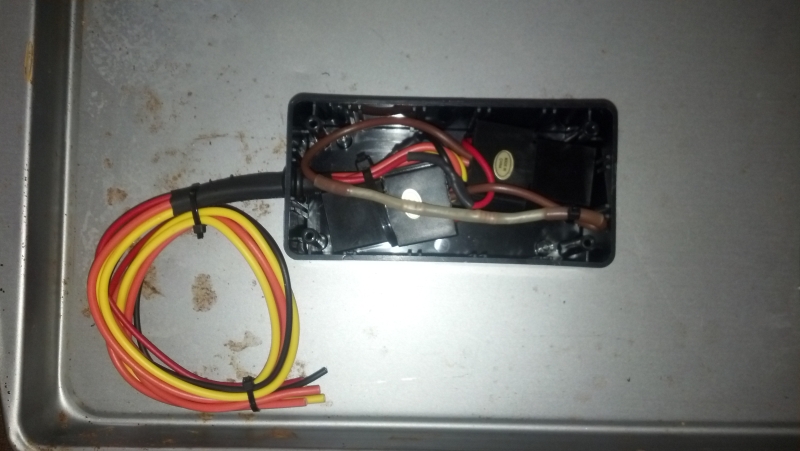
Below is an electrical diagram of how everything will be wired.
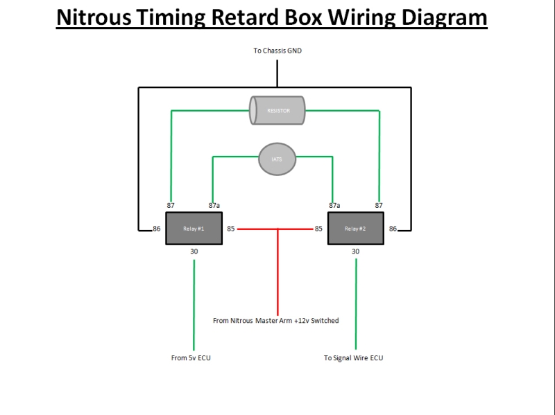
The basic gist of how to wire this is so that when the relays are not powered the signal travels from the ECU, through the IATS, and back to the ECU like it would in stock form. Then when the relays are powered by 12 volts they will switch connection with the pins so that the IATS is temporarily taken out of the circuit and instead the resistors are connected for the ECU to “see” and think it is encountering -40*F IAT’s. Normally I am very adamant about not tricking the ECU with false signals, but in this case it is for the purpose of being on the safe side versus some other hack-job trick to gain power at the cost of safety so it will be ok. The IATS does not have a positive and negative pole so you don’t have to worry much about which wire coming from the ECU that you hook up to which Pin 30 on Relay #1 or #2. For those of you who are also skilled in DC wiring I understand that there is more than one way to wire the relay(s) in this box to allot the IATS signal to be bypassed, but this is the way I prefer to do it. So that is what my diagram is geared towards. NOTE: DO NOT USE CRIMPED BUTT CONNECTORS to connect the wires! You will have a total of 6 wires exiting the box that will route to various places on the car. The first two will be the 12v power and ground wires that activate the relays themselves, in the diagram above that would be the single red and single black wire that split off and each route to pins 85 and 86 on the relays. Then the next two wires that exit will be the wires that will connect to your wires coming from the IATS. In the diagram above those would be the wires coming from pin 87a on each of the relays. The last 2 wires that will exit the box will be the ones that attach to your vehicle electrical harness. According to the diagram above these will be the wires coming from pin 30 on each of the relays.
Activating the Box: Now there are a few options of how you can send 12 volts of power to these relays. You can just keep it simple and run an extra power wire to the box from your nitrous master arm switch or you can run 12 volts from the solenoid activation wire in your nitrous controller. The first choice will mean that the ECU will “see” a -40*F IAT at all times that the master arm switch is flipped, while the second choice will mean that the ECU will only “see” a -40*F IAT when the solenoids are being powered (aka spraying). Before some of you start asking, well why trick the ECU into thinking it is seeing -40*F temps when the nitrous is sure to cool down the IAT’s to that cold of a temp in reality? Well the difference is that there will ALWAYS be a delay time between what the actual intake temps have dropped to on the nitrous versus what the IATS is reading. The IATS just aren’t quick enough to react to temperature changes to keep the engine from knocking for the first few seconds of nitrous activation which is what gives this mod purpose. The ECU only checks IAT’s 2 times a second so in theory if you hook the box up to a solenoid trigger wire then there can be a chance of a slight delay between when the noids are powered versus when the computer “sees” the -40*F temp and pulls timing. Just something to think about.
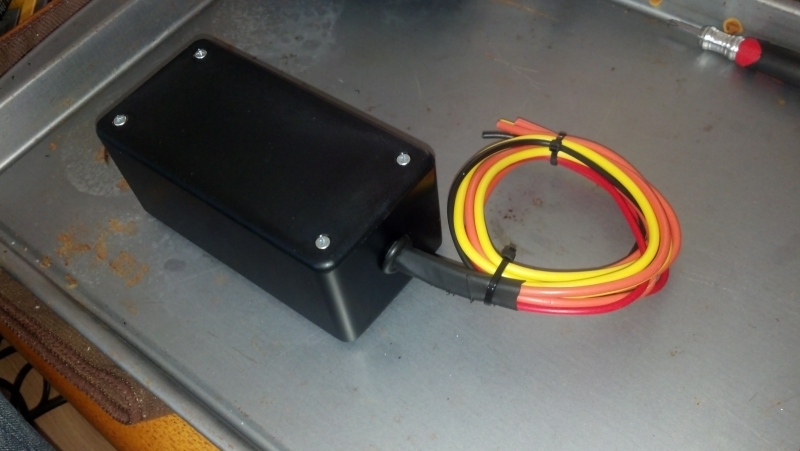
Locating the Box: While you could seal the box with silicone and keep it under the hood I would suggest that it be located inside the cabin somewhere, perhaps under the dash somewhere. You don’t really need access to the box to activate it so it can be tucked up somewhere hidden. Just make sure that if you mount the box away from the IATS that you make good connections with solder and heat shrink tubing on all sensor wire connections so that you don’t inadvertently add more resistance that isn’t accounted for in the IATS Calibration Table.
Extra options/Multiple Timing Retard Settings: One other item worth mentioning is for those of you who may want to retard different amounts of timing with the flip of a rotary switch for whatever reason. You can use this box for that too but you will need to do a few extra things. First off you will need to go to the next coldest cell in the IATS Spark Adder and Multiplier Tables and input whatever spark retard value in them. Then reference the IATS Calibration Table to see what amount of IATS resistance in ohms that ECU expects to see with that temperature so you know how much total resistance your resistor(s) need to add up to or slightly exceed when wired in series. After this you will add in the rotary switch between Pin 87 on Relay #1 and Pin 87 on Relay #2. The wire coming from Pin 87 on Relay #1 will go to the common pole on the rotary switch. Then the first resistor set for the coldest IAT Spark Retard setting will go on Pole #1 of the rotary switch and connect to Pin 87 on Relay #2. The second resistor set for the second coldest IAT Spark Retard setting will connect to rotary switch Pole #2 and connect to Pin 87 on Relay #2 also, and so on and so forth for further Spark Retard settings. Just remember that you are limited on the amount of IATS Spark Adder temperature cells that you can use before getting into cells that you may actually use while daily driving your car in normal weather.
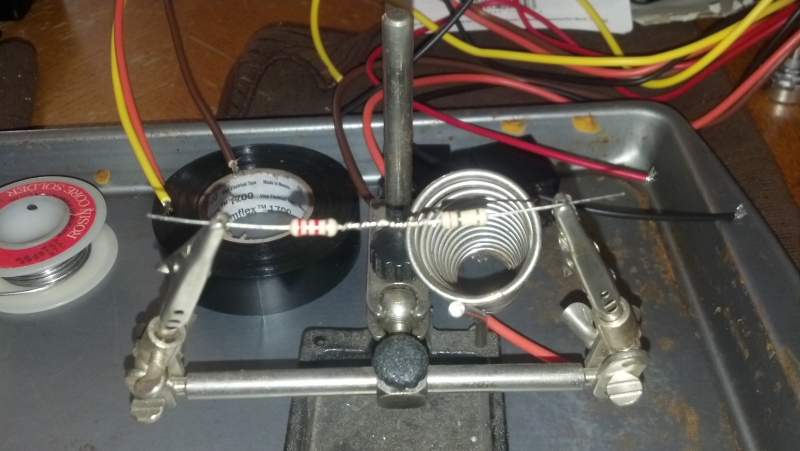
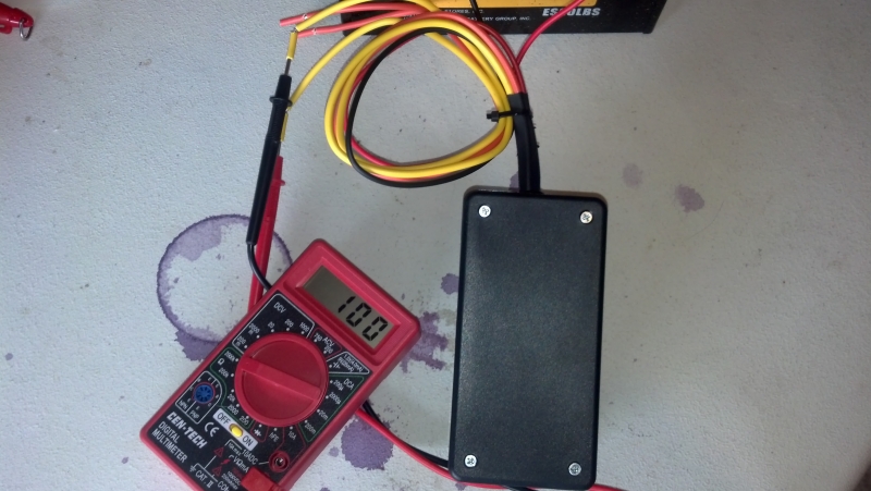
This is the resistance, measured in the thousands of ohms, that the ECU will see when the box is powered thus making it think it is encountering -40*F intake temps.
I hope this mod helps those of you who want an inexpensive and effective way to retard your spark timing while spraying nitrous. There are some other options for how you can set your timing retard without having access to HP Tuners or other tuning platform so if you want to do something like this but don’t have the ability to modify your tune itself, just ask and alternative options can be provided. They aren’t quite as good as directly modifying the IAT Spark Tables, but it is a viable second option. Overall it is a pretty simple setup, especially if you are familiar with DC wiring and have access to HP Tuners, EFILive, or other GM custom tuning platform.
The basic gist of how to wire this is so that when the relays are not powered the signal travels from the ECU, through the IATS, and back to the ECU like it would in stock form. Then when the relays are powered by 12 volts they will switch connection with the pins so that the IATS is temporarily taken out of the circuit and instead the resistors are connected for the ECU to “see” and think it is encountering -40*F IAT’s. Normally I am very adamant about not tricking the ECU with false signals, but in this case it is for the purpose of being on the safe side versus some other hack-job trick to gain power at the cost of safety so it will be ok. The IATS does not have a positive and negative pole so you don’t have to worry much about which wire coming from the ECU that you hook up to which Pin 30 on Relay #1 or #2. For those of you who are also skilled in DC wiring I understand that there is more than one way to wire the relay(s) in this box to allot the IATS signal to be bypassed, but this is the way I prefer to do it. So that is what my diagram is geared towards. NOTE: DO NOT USE CRIMPED BUTT CONNECTORS to connect the wires! You will have a total of 6 wires exiting the box that will route to various places on the car. The first two will be the 12v power and ground wires that activate the relays themselves, in the diagram above that would be the single red and single black wire that split off and each route to pins 85 and 86 on the relays. Then the next two wires that exit will be the wires that will connect to your wires coming from the IATS. In the diagram above those would be the wires coming from pin 87a on each of the relays. The last 2 wires that will exit the box will be the ones that attach to your vehicle electrical harness. According to the diagram above these will be the wires coming from pin 30 on each of the relays.
Activating the Box: Now there are a few options of how you can send 12 volts of power to these relays. You can just keep it simple and run an extra power wire to the box from your nitrous master arm switch or you can run 12 volts from the solenoid activation wire in your nitrous controller. The first choice will mean that the ECU will “see” a -40*F IAT at all times that the master arm switch is flipped, while the second choice will mean that the ECU will only “see” a -40*F IAT when the solenoids are being powered (aka spraying). Before some of you start asking, well why trick the ECU into thinking it is seeing -40*F temps when the nitrous is sure to cool down the IAT’s to that cold of a temp in reality? Well the difference is that there will ALWAYS be a delay time between what the actual intake temps have dropped to on the nitrous versus what the IATS is reading. The IATS just aren’t quick enough to react to temperature changes to keep the engine from knocking for the first few seconds of nitrous activation which is what gives this mod purpose. The ECU only checks IAT’s 2 times a second so in theory if you hook the box up to a solenoid trigger wire then there can be a chance of a slight delay between when the noids are powered versus when the computer “sees” the -40*F temp and pulls timing. Just something to think about.
Locating the Box: While you could seal the box with silicone and keep it under the hood I would suggest that it be located inside the cabin somewhere, perhaps under the dash somewhere. You don’t really need access to the box to activate it so it can be tucked up somewhere hidden. Just make sure that if you mount the box away from the IATS that you make good connections with solder and heat shrink tubing on all sensor wire connections so that you don’t inadvertently add more resistance that isn’t accounted for in the IATS Calibration Table.
Extra options/Multiple Timing Retard Settings: One other item worth mentioning is for those of you who may want to retard different amounts of timing with the flip of a rotary switch for whatever reason. You can use this box for that too but you will need to do a few extra things. First off you will need to go to the next coldest cell in the IATS Spark Adder and Multiplier Tables and input whatever spark retard value in them. Then reference the IATS Calibration Table to see what amount of IATS resistance in ohms that ECU expects to see with that temperature so you know how much total resistance your resistor(s) need to add up to or slightly exceed when wired in series. After this you will add in the rotary switch between Pin 87 on Relay #1 and Pin 87 on Relay #2. The wire coming from Pin 87 on Relay #1 will go to the common pole on the rotary switch. Then the first resistor set for the coldest IAT Spark Retard setting will go on Pole #1 of the rotary switch and connect to Pin 87 on Relay #2. The second resistor set for the second coldest IAT Spark Retard setting will connect to rotary switch Pole #2 and connect to Pin 87 on Relay #2 also, and so on and so forth for further Spark Retard settings. Just remember that you are limited on the amount of IATS Spark Adder temperature cells that you can use before getting into cells that you may actually use while daily driving your car in normal weather.
This is the resistance, measured in the thousands of ohms, that the ECU will see when the box is powered thus making it think it is encountering -40*F intake temps.
I hope this mod helps those of you who want an inexpensive and effective way to retard your spark timing while spraying nitrous. There are some other options for how you can set your timing retard without having access to HP Tuners or other tuning platform so if you want to do something like this but don’t have the ability to modify your tune itself, just ask and alternative options can be provided. They aren’t quite as good as directly modifying the IAT Spark Tables, but it is a viable second option. Overall it is a pretty simple setup, especially if you are familiar with DC wiring and have access to HP Tuners, EFILive, or other GM custom tuning platform.
 04-29-2012, 09:20 AM
#4
TECH Apprentice
iTrader: (2)

Join Date: Jul 2005
Location: Texas
Posts: 305
Likes: 0
Received 0 Likes
on
0 Posts
Great write up man! This is good for the DIY's. One question. The resistors you used are not diode resistors right? Meaning they can be soldered in either direction.
04-29-2012, 01:13 PM
#5
Extra options/Multiple Timing Retard Settings: One other item worth mentioning is for those of you who may want to retard different amounts of timing with the flip of a rotary switch for whatever reason. You can use this box for that too but you will need to do a few extra things. First off you will need to go to the next coldest cell in the IATS Spark Adder and Multiplier Tables and input whatever spark retard value in them. Then reference the IATS Calibration Table to see what amount of IATS resistance in ohms that ECU expects to see with that temperature so you know how much total resistance your resistor(s) need to add up to or slightly exceed when wired in series. After this you will add in the rotary switch between Pin 87 on Relay #1 and Pin 87 on Relay #2. The wire coming from Pin 87 on Relay #1 will go to the common pole on the rotary switch. Then the first resistor set for the coldest IAT Spark Retard setting will go on Pole #1 of the rotary switch and connect to Pin 87 on Relay #2. The second resistor set for the second coldest IAT Spark Retard setting will connect to rotary switch Pole #2 and connect to Pin 87 on Relay #2 also, and so on and so forth for further Spark Retard settings. Just remember that you are limited on the amount of IATS Spark Adder temperature cells that you can use before getting into cells that you may actually use while daily driving your car in normal weather.
However, this part right here with the multiple resistances I haven't seen accomplished yet. Nice job.
 04-29-2012, 03:05 PM
#6


Trending Topics
04-29-2012, 05:27 PM
#8
Can you elaborate more on how the COS5 works? Custom Operating System I presume?
Does it give you two separate timing tables?
What about fueling for a dry kit? Two separate tables?
I have heard there is a 2 step function on Efilive with a COS, is this true?
04-29-2012, 05:47 PM
#9
04-29-2012, 06:01 PM
#10
Oh I know I wasn't the first person to think of this, once I looked around on the forums after I thought of the idea that became apparent. But the main reason for this writeup is because no one else has ever taken the time to post a "HOW TO" of the process. I actually did this project for the sole purpose of making this writeup to guide the folks that have little to no wiring or tuning experience to be able to do this mod and benefit from it. That little box I made will sit and gather dust next to my other nitrous system parts in the garage because I made it without having a use for it currently.
04-29-2012, 06:08 PM
#12
I have heard of the EFILive COS5. I am curious as to how the ECU is triggered to use the retard values in the nitrous spark table? Is a certain sensor, such as the IATS grounded with a switch and that is what does it? Or is it something else?
04-29-2012, 06:31 PM
#13
Oh I know I wasn't the first person to think of this, once I looked around on the forums after I thought of the idea that became apparent. But the main reason for this writeup is because no one else has ever taken the time to post a "HOW TO" of the process. I actually did this project for the sole purpose of making this writeup to guide the folks that have little to no wiring or tuning experience to be able to do this mod and benefit from it. That little box I made will sit and gather dust next to my other nitrous system parts in the garage because I made it without having a use for it currently.
04-29-2012, 06:32 PM
#14
Yes, it is a custom operating system and yes a separate table for spark.
This is the perfect solution for dry nitrous because you can run a normal fuel and spark routine, then when triggered the n20 fuel and spark can correct for the nitrous. The system will also work well with wet, mainly using it as a spark retard system when triggered.
A general run down of the additional COS functions:
1. TPS VS VE. When enabled, you can use TPS VS VE to tune SD instead of RPM VS KPA. You can disable this function and simultaneously swap to the regular VE table by adjusting KPA/TPS/RPM disable values.
2. BOOST VE TABLE: 3 Bar system. If you have boost, you want this! You can tune your VE table all the way to 43psi. Though most boost guys run COS3(which doesn't have n2o functions).
3. IAT VE MULTIPLIER: Allows you to adjust fuel based on IAT. Good for SD.
4 N2O MONITOR VE MULTIPLIER: This is the nitrous tool for fuel adjustment and only works when the nitrous system is triggered ON.
It is RPM based like number 5. Otherwise, this has no affect.
5. N2O MONITOR TIMING TABLE: The table I listed above for retard or advance.
6. BOOST TIMING TABLE : Used from 105 to 285KPA or from 14 to 43psi.
7. OPEN LOOP COMMANDED FUEL MULTIPLIER: This is really good if you run OL SD. On startup you can adjust AFR based on ECT
COS5 is activated when PIN56 (Red Connector) of your PCM is grounded.
I use my arming switch to activate a ground relay to trigger the ground connection.
 04-29-2012, 08:17 PM
#15
All it is would be a simply multi-position rotary switch that you can get from a placed like Radio Shack. The common pole would be attached to pin 87 coming from relay #1 and then you would wire a set of resistors equaling the amount of total resistance needed to equate to whatever IAT you are trying to represent to the first position pin and then attach the other side of the resistors to pin 87 on Relay #2, and then wire another set of resistors equaling a different amount of total resistance representing another IAT value to the second position pin on the rotary switch and then also wire the other side of those to pin 87 on Relay #2 as well. So the rotary switch is not providing the different resistance settings itself, it is just allowing you to route your circuit through different sets of resistors that represent different IAT's. It is a rotary switch used in conjunction with resistors of differing resistance; coupled with reconfiguring more cells in the IAT Spark Adder Tables in the tune that will give you the multiple settings of spark retardation.
04-29-2012, 09:04 PM
#16
I use a relay setup as follows:
Pin87-Ground Source
Pin30-Pin56 of PCM(RedHarness)
Pin85-Ground
Pin86-Arming Switch (+)
04-29-2012, 09:36 PM
#17
All it is would be a simply multi-position rotary switch that you can get from a placed like Radio Shack. The common pole would be attached to pin 87 coming from relay #1 and then you would wire a set of resistors equaling the amount of total resistance needed to equate to whatever IAT you are trying to represent to the first position pin and then attach the other side of the resistors to pin 87 on Relay #2, and then wire another set of resistors equaling a different amount of total resistance representing another IAT value to the second position pin on the rotary switch and then also wire the other side of those to pin 87 on Relay #2 as well. So the rotary switch is not providing the different resistance settings itself, it is just allowing you to route your circuit through different sets of resistors that represent different IAT's. It is a rotary switch used in conjunction with resistors of differing resistance; coupled with reconfiguring more cells in the IAT Spark Adder Tables in the tune that will give you the multiple settings of spark retardation.
You took an older idea that has worked well for many and made it better.

 04-30-2012, 09:50 AM
#20
Still all in all, everybody who talks about how cheap this is to do, don't ever include the cost of buying HPT or EFI live. You have to think about the guy who has nothing at all and is starting from scratch. Which route do you think he is going to go?
The only good thing I see from this is having multi stage retard for multiple shots.
The only good thing I see from this is having multi stage retard for multiple shots.