When you click on links to various merchants on this site and make a purchase, this can result in this site earning a commission. Affiliate programs and affiliations include, but are not limited to, the eBay Partner Network.
I recently installed my nitrous kit and some other parts and I figured I would share some pics of the install. I'd like to thank Houston and all the rest of the guys at Nitrous Outlet for getting me squared away. These guys truly set the standard for exceptional customer service.
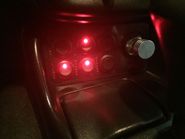
For the switch panel, I went with the Emblempros 6 button cig lighter switch plate which has buttons for purge, N2O arm, cutout, warmer, opener, and line lock. Great company to deal with and also exceptional customer service!
The following was installed:
LPE LNC-2000
NOS progressive mini controller
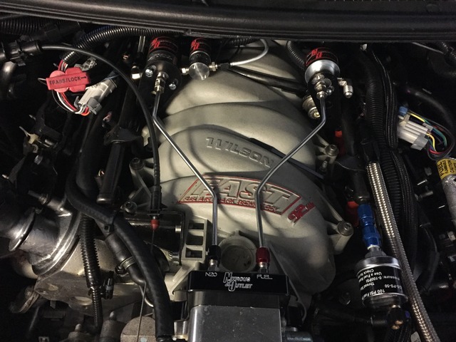
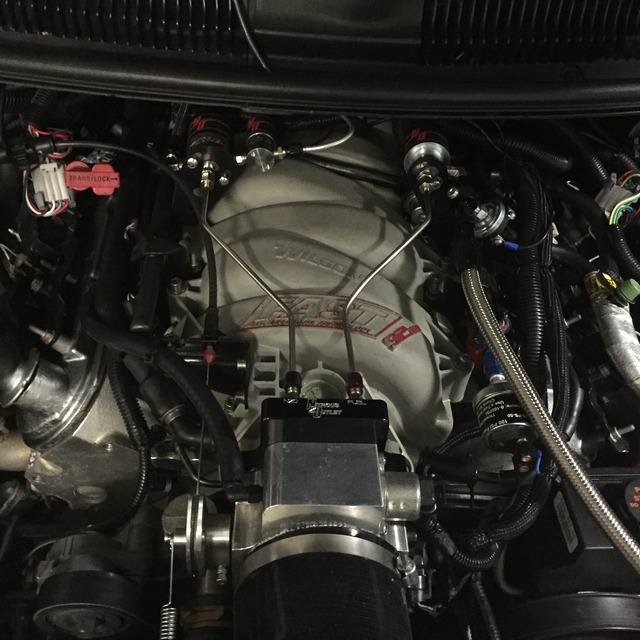
Nitrous Outlet 98-02 F-body FAST 92mm plate kit
Nitrous Outlet 10 lb x-series bottle
Nitrous Outlet Bottle heater
Nitrous Outlet Remote Bottle Opener
Nitrous Outlet fuse panel area stand alone fuel system
Nitrous Outlet 4AN purge
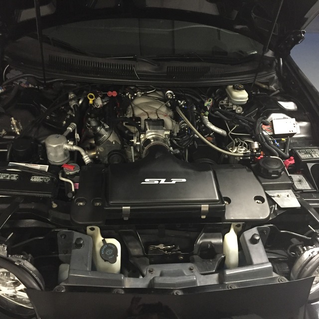
SLP line lock
DMH dual cutouts
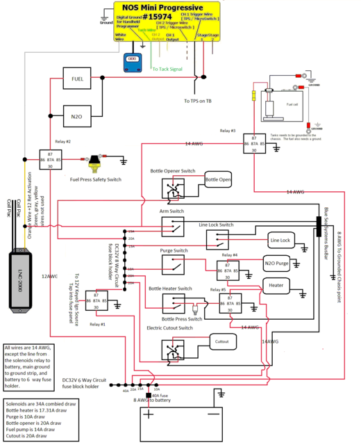
I put together this wiring diagram using M$ paint.
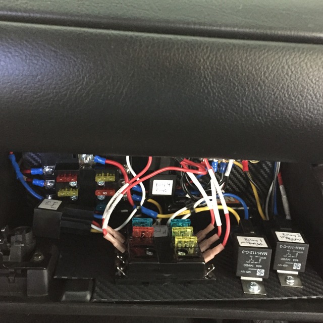
I didn't want to drill in the glove box and I wanted all the relays and fuses to be easily accessible, so I mounted them on a piece of Plexiglas covered with 3M Di-noc.
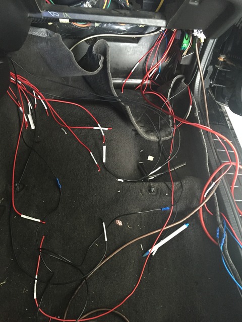
Wiring it up:
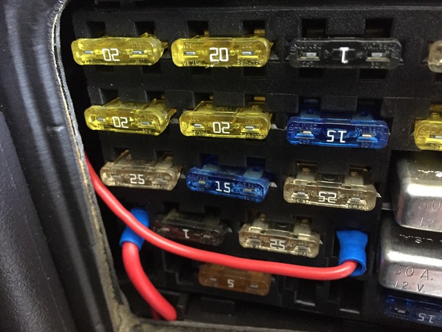
Voltage and resistance all read good despite not soldering. I used a fuse tap to run the 12v keyed source right from the fuse box. I have an inline 30A fuse on it.
Inside the glove box I have 4 relays, a bus bar, and 2 distribution blocks. The bus bar has some rubber underneath it between it and the Plexiglas. I ran a 4 awg ground wire from the chassis to the bus bar, and all my grounds for the relays and switches to the bus bar. I used address labels for making printed wire labels for each wire.
Switch panel. Forget about using the adhesive that comes on the back of the panel.... you will want to use a much stronger adhesive to attached it to the console. JB Weld worked fine for me.
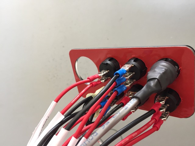
I made the wires extra long coming out the back of the switch panel so that removing the center console doesn't result in any bent wires. All wires going to the switches are labeled just after the connection points.
Nos Mini is mounted with 3M Velcro.
The dual cutouts from DHM work flawlessly. I have the cutouts running right off the Y pipe. Nice and quiet when I pull in the garage, and able to wake the dead when on the street. The SLP line lock needed some extra care to stop the leaks.
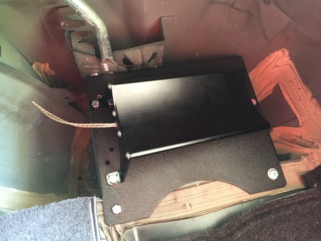
Nitrous outlet makes an F-body bottle mounting plate for easy mounting of the bottle. I had to use 1 inch spacers under the bolts to raise the bottle up a bit for perfect clearance.
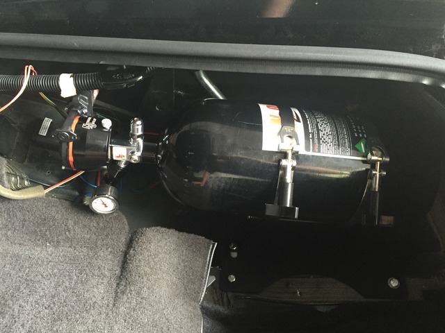
Bottle mounted with remote bottle opener and heater. Relay #5 mounted back there as well resulting in less wiring having to be routed to the glove box.
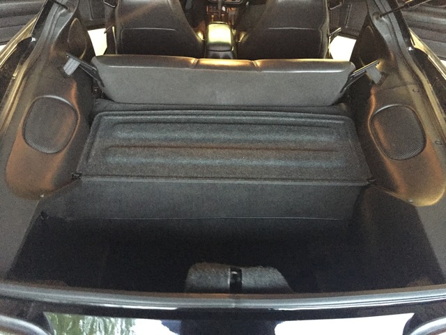
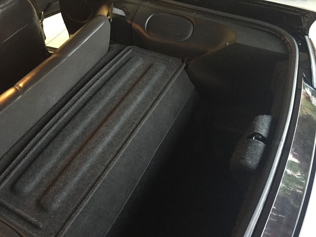
Bottle hidden
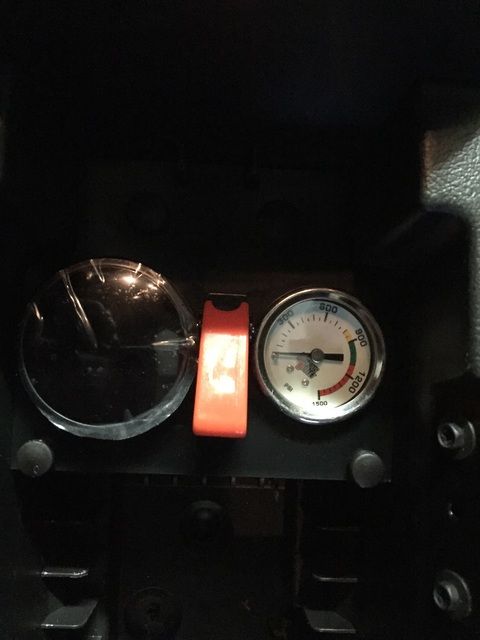
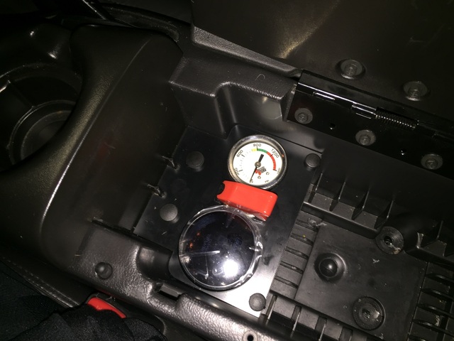
I will run a hidden N2O gauge which will be located in the center console compartment and to do that I will run a T fitting off of the 4AN nitrous line which is current connected from the bottle to the solenoid.
Solenoid, LNC2000 mounting, and under hood wiring
I used the hole behind the ECM to run all my lines from the engine bay into the cabin.
I'm using the stock fuel rails on my fast 92. Mounted on the fuel rail is a fuel pressure sending unit for the electric fuel gauge. To mount the gauge on the factory fuel rail I used:
Earl's 916104ERL - Straight, -4 AN Female to 1/8 in. NPT Male
Earl's 991001ERL - Straight, Female 1/8 in. NPT to Female 1/8 in. NPT
For the purge, I ran it right though the center hole of the cowl after removing the push pin fastener in the cowl.
The fuel line coming off the stand alone is -6AN. I have a -4AN elbow coming off my fuel solenoid, so I used a Nitrous Outlet -4AN female to male swivel fitting that has dual 1/8th ports to mount my fuel pressure safety switch, and then I used a female -4AN to male -6AN expander off of the swivel fitting to hook up the fuel feed line coming from the stand alone.
Plugs are NGK-BR7EF gapped at 0.35 Jets are setup for a 100 shot for starters, and will surely bump it up from there.
Ready to roll
Last edited by 5.7stroker; 05-26-2016 at 09:06 PM.
Great write up! Subscribed. This is next on my to do list this summer. How bad was the wiring to deal with? Did the H/C/I, clutch, and S60 swap on mine in the garage. Haven't done a ton of wiring though.
Great write up! Subscribed. This is next on my to do list this summer. How bad was the wiring to deal with? Did the H/C/I, clutch, and S60 swap on mine in the garage. Haven't done a ton of wiring though.
Thanks! The wiring isn't bad, just very time consuming and you definitely want to make a wiring schematic and label all the wires.
Originally Posted by kingtal0n
it is cycling your fuel solenoids? Are you running a separate fuel pump/feed (that what you mean by standalone?)
I'm using a progressive nitrous controller and this separate fuel pump/feed:
Thanks for all the positive feedback everyone! Now I just need to worry about spraying too much. 100 turns into 150 which turns into 200 which turns into 300 real quick...
Spray it until you start finding the limits of you car. There is at least (1) 8 second car stock bottom end so you can go fast with what you got for sure.
Installed my custom center console switch panel today that 2BAD4U custom made for me. The fitment is perfect and the craftsmanship is top notch.
I was pretty maxed out for switch and gauge placement:
I needed a place for my mechanical N2O gauge and my LC-2 wideband gauge. I also needed another switch to function as a power on source for the line lock switch. It's just not worth the risk of the line lock switch on my 6 button panel accidentally being turned on during movement, so I wanted an additional switch for safety. No issues with running an N2O line off a T fitting up through the center console. I think I may have him make me another custom panel that covers the CD holders as seen in the last pic.
For the 6 panel gauge, the wiring makes removal of the shifter bezel difficult, as each wire must be removed from each switch on the back of the panel. I used some Testors brand model paint and painted the plastic terminal on the end of each wire the same color as the area near the spade on the back of each switch that it is hooked to. This way, everything is color coded and I don't have to fumble around with which wire goes where every time I need to disconnect the wires. 20+ different colors.
Last edited by 5.7stroker; 08-01-2017 at 01:48 PM.
1. Installed a 6" fan on top of my B&M trans cooler with switch. Purchased from ebay user "american-volt"
2. Updated attached wiring diagram with Innovate LC-2 details.
3. Replaced mechanical N2O pressure gauge with electric one.
4. Installed electrical oil pressure gauge.
5. Removed LNC-2000, timing pulled by using Red PCM Pin #53, ignition retard signal in HP tuners.
Pics to follow.
Last edited by 5.7stroker; 03-23-2017 at 09:34 PM.

 05-26-2016, 09:00 PM