
Need Drive-By-Wire Help
 06-22-2009, 12:03 AM
#1

I have an 08 TBSS that I am putting a T-56 into. I'm running the motor stand alone using a 07 CTS-V ECM. It starts and runs but I cannot get the throttle to work. Here are the codes that I get.
[ECM] P0315 - Crankshaft Position System Variation Not Learned (SES) (Pending) (Old) (History) (Current) (Immature)
[ECM] P060D - Internal Control Module Accelerator Pedal Position Performance (SES) (Pending) (History) (Current) (Immature)
[ECM] P2119 - Throttle Actuator Control Throttle Body Range/Performance (Pending) (Old) (History) (Current) (Immature)
[ECM] P2138 - Throttle/Pedal Position Sensor/Switch D/E Voltage Correlation (SES) (Pending) (History) (Current) (Immature)
[ECM] P0315 - Crankshaft Position System Variation Not Learned
[ECM] P060D - Internal Control Module Accelerator Pedal Position Performance
[ECM] P2138 - Throttle/Pedal Position Sensor/Switch D/E Voltage Correlation
I also scanned it with status bits and got this:
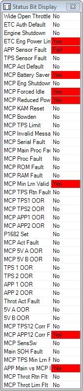
The accelerator pedal is a brand new from GM 07 CTS-V pedal. I had to swap pins A and C at the APP connector to match the pinout for the CTS-V pedal. I verified that both 5v and low refs are good at the APP connector.
Here is the GM description for the APP on a 07 CTS-V:
The APP sensors are used to determine the pedal angle. The engine control module (ECM) provides each APP sensor a 5-volt reference circuit and a low reference circuit. The APP sensors provide the ECM with signal voltage proportional to the pedal movement. The APP sensor 1 signal voltage at rest position is less than 1 volt and increases to above 4 volts as the pedal is actuated. The APP sensor 2 signal voltage at rest position is near 0.5 volt and increases to more than 2 volts as the pedal is actuated.
I tested for voltage on the two APP signal wires two different ways.
The first time I tested, I removed the signal wire that was being tested from the ecm connetor, put the positve probe to that wire, and then put the negative probe to the negative battery terminal.
The second time I removed the signal wire from the connector, and then inserted a short piece of wire (terminal on one end and bare wire on the other end) into the ECM connector in the same location that the signal wire was removed from. I put the positive probe on the signal wire coming from the pedal and I put the negative probe on the short piece of wire going into the ecm. This way it uses the ground throught the ECM and doesnt bypass it by going straight to the battery. The voltages would never steady out on the 2nd method, they were always fluctuating just slightly.
Here are the results:
1st Test (Spot on with the GM description)
APP 1 - Rest = 0.974v
APP 1 - Floored = 4.13v
APP 2 - Rest = 0.489v
APP 2 - Floored = 2.051v
2nd Test
APP 1 - Rest = 0.787v
APP 1 - Floored = 3.2v
APP 2 - Rest = 0.331v
APP 2 - Floored = 1.42v
At this point I think I have a bad ECM but wanted to get some opinions before I go buy another one.
Thanks!!!
[ECM] P0315 - Crankshaft Position System Variation Not Learned (SES) (Pending) (Old) (History) (Current) (Immature)
[ECM] P060D - Internal Control Module Accelerator Pedal Position Performance (SES) (Pending) (History) (Current) (Immature)
[ECM] P2119 - Throttle Actuator Control Throttle Body Range/Performance (Pending) (Old) (History) (Current) (Immature)
[ECM] P2138 - Throttle/Pedal Position Sensor/Switch D/E Voltage Correlation (SES) (Pending) (History) (Current) (Immature)
[ECM] P0315 - Crankshaft Position System Variation Not Learned
[ECM] P060D - Internal Control Module Accelerator Pedal Position Performance
[ECM] P2138 - Throttle/Pedal Position Sensor/Switch D/E Voltage Correlation
I also scanned it with status bits and got this:
The accelerator pedal is a brand new from GM 07 CTS-V pedal. I had to swap pins A and C at the APP connector to match the pinout for the CTS-V pedal. I verified that both 5v and low refs are good at the APP connector.
Here is the GM description for the APP on a 07 CTS-V:
The APP sensors are used to determine the pedal angle. The engine control module (ECM) provides each APP sensor a 5-volt reference circuit and a low reference circuit. The APP sensors provide the ECM with signal voltage proportional to the pedal movement. The APP sensor 1 signal voltage at rest position is less than 1 volt and increases to above 4 volts as the pedal is actuated. The APP sensor 2 signal voltage at rest position is near 0.5 volt and increases to more than 2 volts as the pedal is actuated.
I tested for voltage on the two APP signal wires two different ways.
The first time I tested, I removed the signal wire that was being tested from the ecm connetor, put the positve probe to that wire, and then put the negative probe to the negative battery terminal.
The second time I removed the signal wire from the connector, and then inserted a short piece of wire (terminal on one end and bare wire on the other end) into the ECM connector in the same location that the signal wire was removed from. I put the positive probe on the signal wire coming from the pedal and I put the negative probe on the short piece of wire going into the ecm. This way it uses the ground throught the ECM and doesnt bypass it by going straight to the battery. The voltages would never steady out on the 2nd method, they were always fluctuating just slightly.
Here are the results:
1st Test (Spot on with the GM description)
APP 1 - Rest = 0.974v
APP 1 - Floored = 4.13v
APP 2 - Rest = 0.489v
APP 2 - Floored = 2.051v
2nd Test
APP 1 - Rest = 0.787v
APP 1 - Floored = 3.2v
APP 2 - Rest = 0.331v
APP 2 - Floored = 1.42v
At this point I think I have a bad ECM but wanted to get some opinions before I go buy another one.
Thanks!!!
