
Help Disassembling E40 Delphi Micro-64 Connectors
 05-18-2015, 09:17 PM
#1

I'm converting my LS2/E40 harness to standalone. I'm removing some pins but I also want to move a few to different locations.
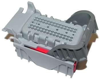
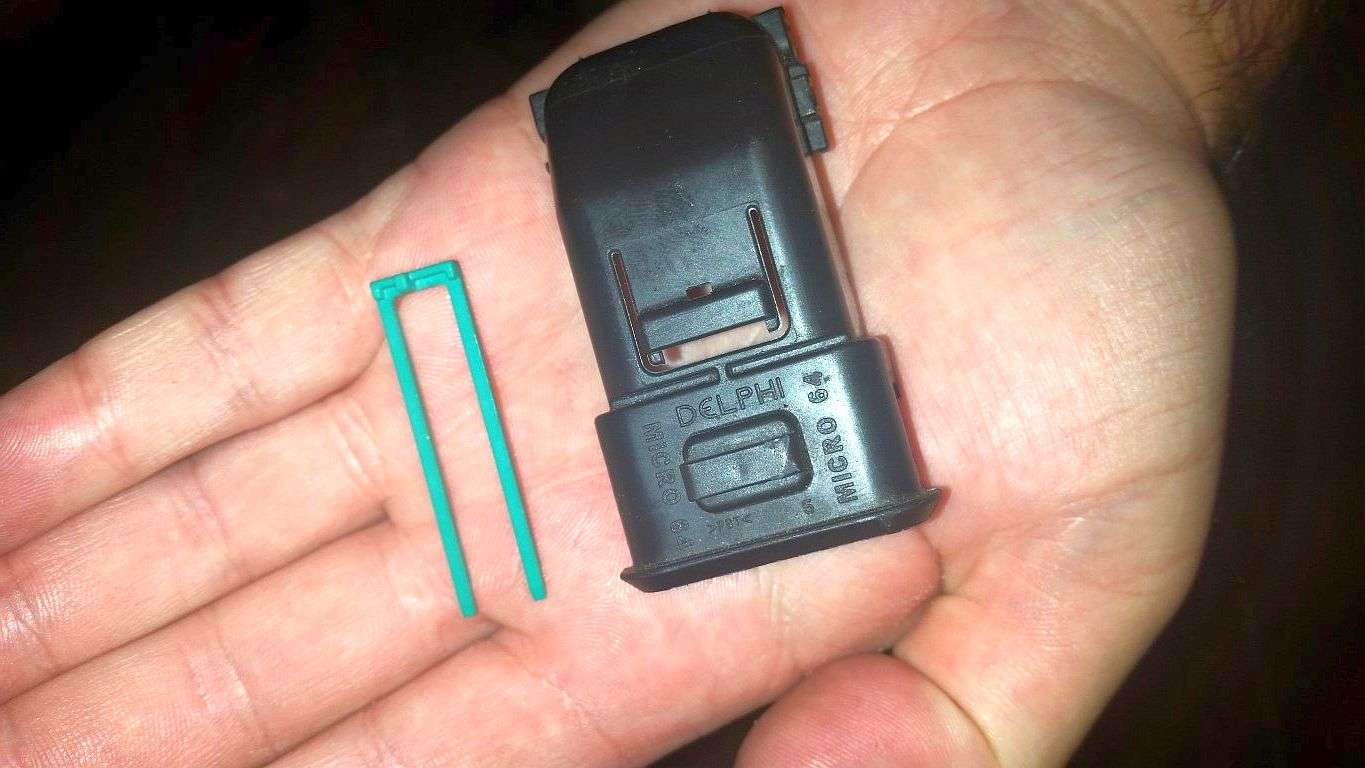
I've successfully disassembled the C3 (gray) 56 pin connector, which as best I can tell, is a Delphi Micro-64 (or MicroPack 64). It appears the C1 and C3 are identical connectors with only the difference being the color; blue vs. gray.
As you can see, I removed the back cover and the pin retainer and using a paperclip, I've been able to remove pins. But in order to reinsert pins and get them fully seated, the connector must come further apart.
I found what appears to be the tech sheet for these connectors. It shows the "nose piece" coming out from the bottom side of the connector (the side that seats to the PCM). I've been messing with this thing for two nights and I just don't see it coming apart like that. It appears there are tabs on the top/back (the side from which the pins are inserted). You can see these tabs in the first and third pictures. While I can see some movement, I'm afraid to force it.
Anyone have experience taking these apart?
Tipsy
 06-11-2015, 05:06 PM
#3
On The Tree

Join Date: Sep 2007
Location: Indiana
Posts: 195
Likes: 0
Received 0 Likes
on
0 Posts

To insert a terminal you do not need to take the connector apart any further. What you need to do is cut back that tape and make sure you can get it straight on. The E40 pins are pretty picky and if you have the terminal slightly bent it can be a pain.
Just make sure when you are de-pinning the terminals you aren't breaking anything.
When you push the terminal in to seat it you should hear a click or at least feel that it's seated properly by slightly pulling and pushing on it and you should feel it barley move.
Just make sure when you are de-pinning the terminals you aren't breaking anything.
When you push the terminal in to seat it you should hear a click or at least feel that it's seated properly by slightly pulling and pushing on it and you should feel it barley move.
06-11-2015, 08:46 PM
#4
To insert a terminal you do not need to take the connector apart any further. What you need to do is cut back that tape and make sure you can get it straight on. The E40 pins are pretty picky and if you have the terminal slightly bent it can be a pain.
Just make sure when you are de-pinning the terminals you aren't breaking anything.
When you push the terminal in to seat it you should hear a click or at least feel that it's seated properly by slightly pulling and pushing on it and you should feel it barley move.
Just make sure when you are de-pinning the terminals you aren't breaking anything.
When you push the terminal in to seat it you should hear a click or at least feel that it's seated properly by slightly pulling and pushing on it and you should feel it barley move.
Tipsy