
LC-1 install
 10-29-2006, 09:27 PM
#1

I just installed my LC-1. I have "OL - Fault" under my Fuel status when I log the default imperial pids. Any ideas? I set my LC-1 up to simulate a narrow band. Do you think I just got the wiring wrong for the NB (4 way connector) or is that somehow normal?
I've attached a log with the suggested pids from the AutoVE tutorial. Just rename it to exclude the .doc extension. The upload manager doesn't allow .efi files.
I'm also getting some Diagnostic Trouble Codes:
P0135 "O2S Heater Performance Bank 1 Sensor 1"
P0154 "O2S Circuit Insufficient Activity Bank 2 Sensor 1"
Thanks!
Last edited by Xtnct00WS6; 10-30-2006 at 10:57 AM.
 10-30-2006, 09:02 PM
#3
TECH Addict
iTrader: (10)
Join Date: Jun 2004
Location: Commerce Twp, MI
Posts: 2,918
Likes: 0
Received 0 Likes
on
0 Posts

I never had any luck with that. I just commanded open loop full time while tuning and turned off all of the front O2 DTCs. This includes the switching ones too.
10-31-2006, 11:22 AM
#4
TECH Enthusiast
iTrader: (14)
Join Date: Apr 2005
Location: NE Ohio
Posts: 591
Likes: 0
Received 0 Likes
on
0 Posts
Originally Posted by Xtnct00WS6
I just double checked my 4 way connection from the LC-1 to the Narrow Band and it's fine. Anyone have any ideas?!
10-31-2006, 12:04 PM
#5
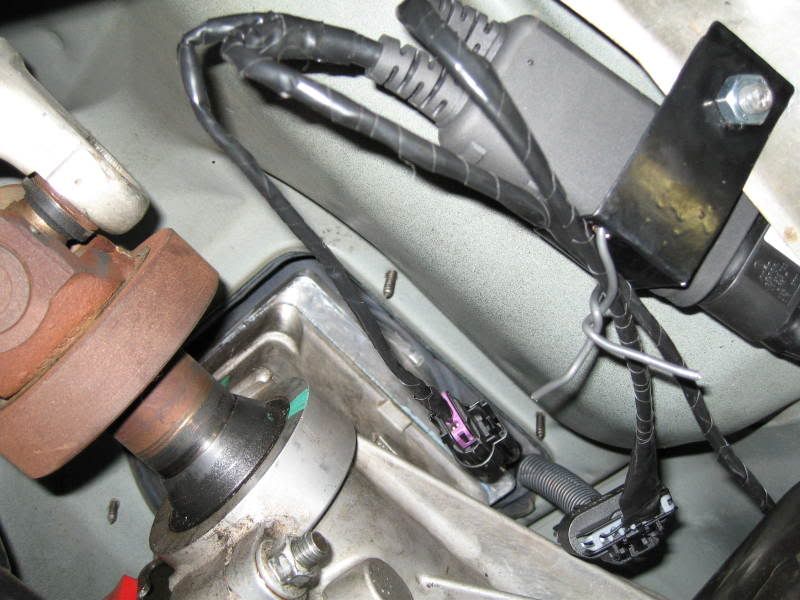
Here's how I did wired everything. I made mine portable by making a sub harness that's permanently in my shift boot.
4-way connector to simulate the NB:
A = NBO2 Signal Low = LC-1 green
B = NBO2 Signal High = LC-1 yellow
C = Heater Ground = LC-1 blue (Should I find a better ground maybe?)
D = Heater Power = LC-1 red
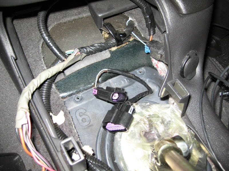
3-way connector:
A = Wideband signal = LC-1 brown --> goes to: FlashScan pin C or E
B = System Ground = LC-1 white --> goes to: FlashScan pin D and pushbutton/LED ground/cathode
C = Calibration = LC-1 black --> goes to: pushbutton/LED positive/anode
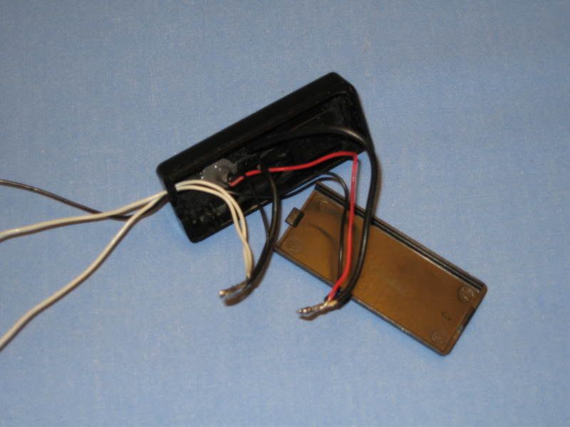
This is how I installed the light and button. It's a AA battery box with its guts ripped out. I found it at RadioShack for really cheap.
6-way connector:
This has both sets of 3 wires from the LC-1 Serial IN and Serial OUT cables. Serial IN goes to the terminator plug and the OUT goes to the Laptop.
I did mine exactly how JoeCar did his. I'm not getting the OL - Fault anymore, but it is staying in OL. For some reason I can log AFR, but can't get the NB simulated properly.
Thanks!
4-way connector to simulate the NB:
A = NBO2 Signal Low = LC-1 green
B = NBO2 Signal High = LC-1 yellow
C = Heater Ground = LC-1 blue (Should I find a better ground maybe?)
D = Heater Power = LC-1 red
3-way connector:
A = Wideband signal = LC-1 brown --> goes to: FlashScan pin C or E
B = System Ground = LC-1 white --> goes to: FlashScan pin D and pushbutton/LED ground/cathode
C = Calibration = LC-1 black --> goes to: pushbutton/LED positive/anode
This is how I installed the light and button. It's a AA battery box with its guts ripped out. I found it at RadioShack for really cheap.
6-way connector:
This has both sets of 3 wires from the LC-1 Serial IN and Serial OUT cables. Serial IN goes to the terminator plug and the OUT goes to the Laptop.
I did mine exactly how JoeCar did his. I'm not getting the OL - Fault anymore, but it is staying in OL. For some reason I can log AFR, but can't get the NB simulated properly.
Thanks!
Last edited by Xtnct00WS6; 10-31-2006 at 11:19 PM.
10-31-2006, 12:22 PM
#6
TECH Enthusiast
iTrader: (14)
Join Date: Apr 2005
Location: NE Ohio
Posts: 591
Likes: 0
Received 0 Likes
on
0 Posts
Nice looking install!
What kind of signal are you getting on the narrow band? Have you measured the actual mV value coming out of the LC-1, both at the LC-1 and at your connector? To help reading the mV signal, you can set the output of analog out1 to 250mV for both the high and low. That'll give your meter something to latch on to.
What kind of signal are you getting on the narrow band? Have you measured the actual mV value coming out of the LC-1, both at the LC-1 and at your connector? To help reading the mV signal, you can set the output of analog out1 to 250mV for both the high and low. That'll give your meter something to latch on to.
11-01-2006, 11:12 AM
#7
I measured the volts coming from the NB connector and it was almost 13 so it seems I'm getting enough power to the LC-1. Do you mean, measure the high and low pins that come from the LC-1 and see if that correlates to what I'm seeing in my logs?
I'm going to try and turn off those codes and see if that enables me to run in Closed Loop.
Thanks!
I'm going to try and turn off those codes and see if that enables me to run in Closed Loop.
Thanks!
Trending Topics
11-01-2006, 11:28 AM
#8
TECH Enthusiast
iTrader: (14)
Join Date: Apr 2005
Location: NE Ohio
Posts: 591
Likes: 0
Received 0 Likes
on
0 Posts
If you are running the LC-1 in NB sim mode, then one of the analog outputs will need to go back to the NB O2 harness on your car.
I believe the Yellow and brown (from LC1) are your two analog output high wires. Be careful not to short the analog outputs when measuring them, that's a quick way to smoke the DAC convertor inside the LC1.
I believe the Yellow and brown (from LC1) are your two analog output high wires. Be careful not to short the analog outputs when measuring them, that's a quick way to smoke the DAC convertor inside the LC1.