'02 SS Steering wheel control LED conversion...
 10-10-2013, 02:27 PM
#1
On The Tree
Thread Starter

Join Date: Apr 2011
Location: San Antonio, Tx
Posts: 129
Likes: 0
Received 0 Likes
on
0 Posts

Working on replacing the lights in the steering wheel controls of my '02 SS.
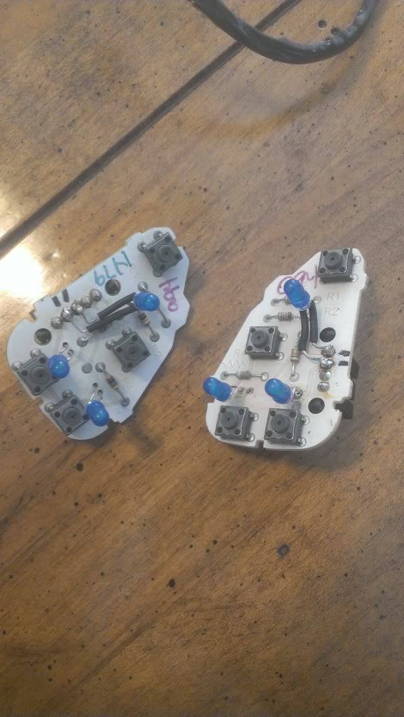
Found a tutorial from a firebird after extensive searching, but once I popped the unit open I found out apparently GM changed the circuit board design by '02; instead of there being one lamp, in '02 there are two lamps and they appear to be run in parallel (but I could be wrong).
Was wondering if anyone here had done it before on the later year F body cars or had a link to a tutorial for doing the conversion on one?
I have matched resistors for my LEDs, I wired in one LED and resistor to the circuit but couldn't get it to light when I tested it, don't know if the system changed from being 12v in later years? Or maybe I got my polarity wrong? Or maybe even the circuit has to be completed in a goofy way to only use 1 LED instead of the 2 incandescent bulbs?
I can try to post pics later if necessary. I would've tried more last night myself, but like a putz I burned the hell out of my finger with my soldering iron; tends to bring workflow to a screeching halt.
 10-10-2013, 09:51 PM
#2
TECH Enthusiast
I couldn't find any info either but I finally figured it out. In the first picture you will see I marked the contacts that power the lights. Sorry I forget which was +/-, you'll have to test for that so you can connect your leds properly. I didn't like the way it looked with 2 so I added a third. I found the easiest way to make everything fit inside the switch was to solder everything in a parallel like it was from the factory. Then I put the resistors down on the harness that connects the 2 switches together.
10-11-2013, 08:28 AM
#3
On The Tree
Thread Starter
Join Date: Apr 2011
Location: San Antonio, Tx
Posts: 129
Likes: 0
Received 0 Likes
on
0 Posts
I couldn't find any info either but I finally figured it out. In the first picture you will see I marked the contacts that power the lights. Sorry I forget which was +/-, you'll have to test for that so you can connect your leds properly. I didn't like the way it looked with 2 so I added a third. I found the easiest way to make everything fit inside the switch was to solder everything in a parallel like it was from the factory. Then I put the resistors down on the harness that connects the 2 switches together.
I ended up getting it all together last night after I got home from work. I'm developing a strange habit of being able to figure out my problem almost immediately after posting the question to LS1 tech, no matter how long I wait to post the question. :/
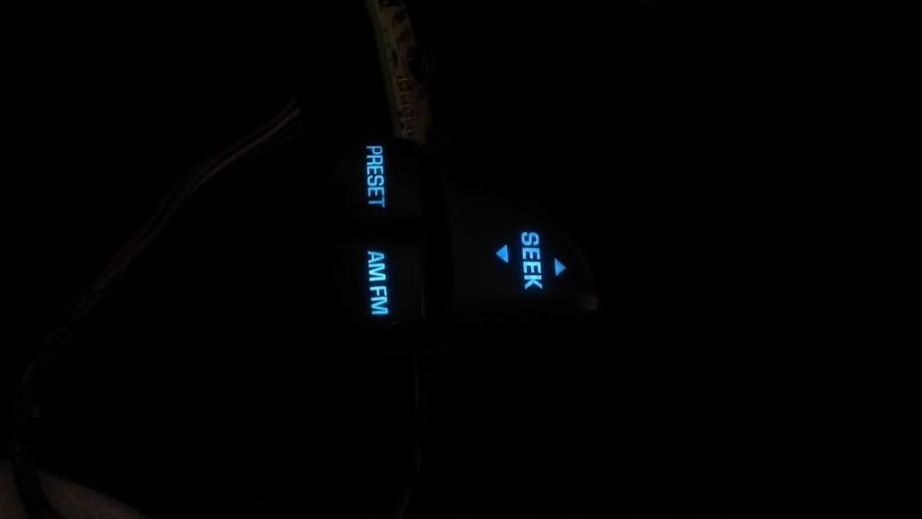
Your setup looks MUCH better than mine though, I only went with one LED for each side. I was able to angle the LED so it distributes light pretty OK (the same or brighter than the stock bulbs), but it's definitely not as clean as your setup.
 10-16-2013, 11:20 AM
#5
TECH Enthusiast

