When you click on links to various merchants on this site and make a purchase, this can result in this site earning a commission. Affiliate programs and affiliations include, but are not limited to, the eBay Partner Network.
First off, I'm not entirely sure this is the right place to post this, but seeing as there isn't really a good place for general wiring/electrical, this seemed as good as any.
I (somewhat) recently embarked on a quest to rewire my car in a way that was simple, serviceable, and reliable. Without getting into too much detail of the car's past, I've been fighting it on the electrical front for over 4 years - as soon as one problem was fixed, two more surfaced. So, being the masochist I am, I decided to essentially redo everything.
Some quick background - the car is a '98, so the first wiring issue was the PCM. I converted the harness to a '99+ by re-pinning the PCM connectors. When things still didn't seem to work right, I decided to rip out the engine harness, tear it apart, and rebuild it. That (obviously) didn't work, because I was not a professional harness builder, so I ordered a harness from BP, with some custom touches to work with my '98 body. After that, I lost my mind and decided the rest of the engine bay wiring needed redone, since half the fuses up there weren't needed anymore. Lots of time, tinkering, and studying wiring diagrams led to this nearly final product. I don't have any pictures of the engine bay harness, but I'll try to explain it.
In order to simplify things, reduce weight, (and partly because I'm an idiot), I removed a lot of things: cruise control, traction control, windshield washers (kept wipers), ABS, security system, air bags, radio/stereo, and EVAP. This is in addition to removing the EGR/AIR when I did the engine work. Also, in the middle of this process, I swapped from auto to t56, so there's that too. In doing all that, I greatly simplified the engine bay secondary harness (the one that doesn't control the engine). I've decreased the number of wires through the firewall down to 21, so I was able to use a cheap weatherpack 22-pin bulkhead there. The in-car harness is where the real tough work came in.
This is the driver's side end of the harness. The 22-pin bulkhead can be seen here on the left. Above it, the clutch safety switch (which grounds the starter relay), the brake light switch, wiper and high beam switches. Below, there are 4 added connectors that go to the door harness and the rear body harness that runs along the driver rocker panel. Below those are the headlight branch, flasher module, and hatch release relay.
Left center here is the gauge cluster connector, and below that is the ignition switch, DLC, flasher, VATS key sensor connector (which I left in just in case), and turn signal/hazard connector. At the top is the DRL module and the A/C control panel branch. The connector below that, I've honestly not figured out. It connects to something that is hiding between the A/C system and the firewall.
Left to right, the center console branch (which is now only 12v power connectors, park brake, and seatbelt switch), BCM, the engine communication branch (for things like tach, speed, etc), and the blower motor connector.
At top, the blower motor relay and the headlight door module connectors, to the right are the connections between the engine control fuse box (black box on lower right) and the PCM.
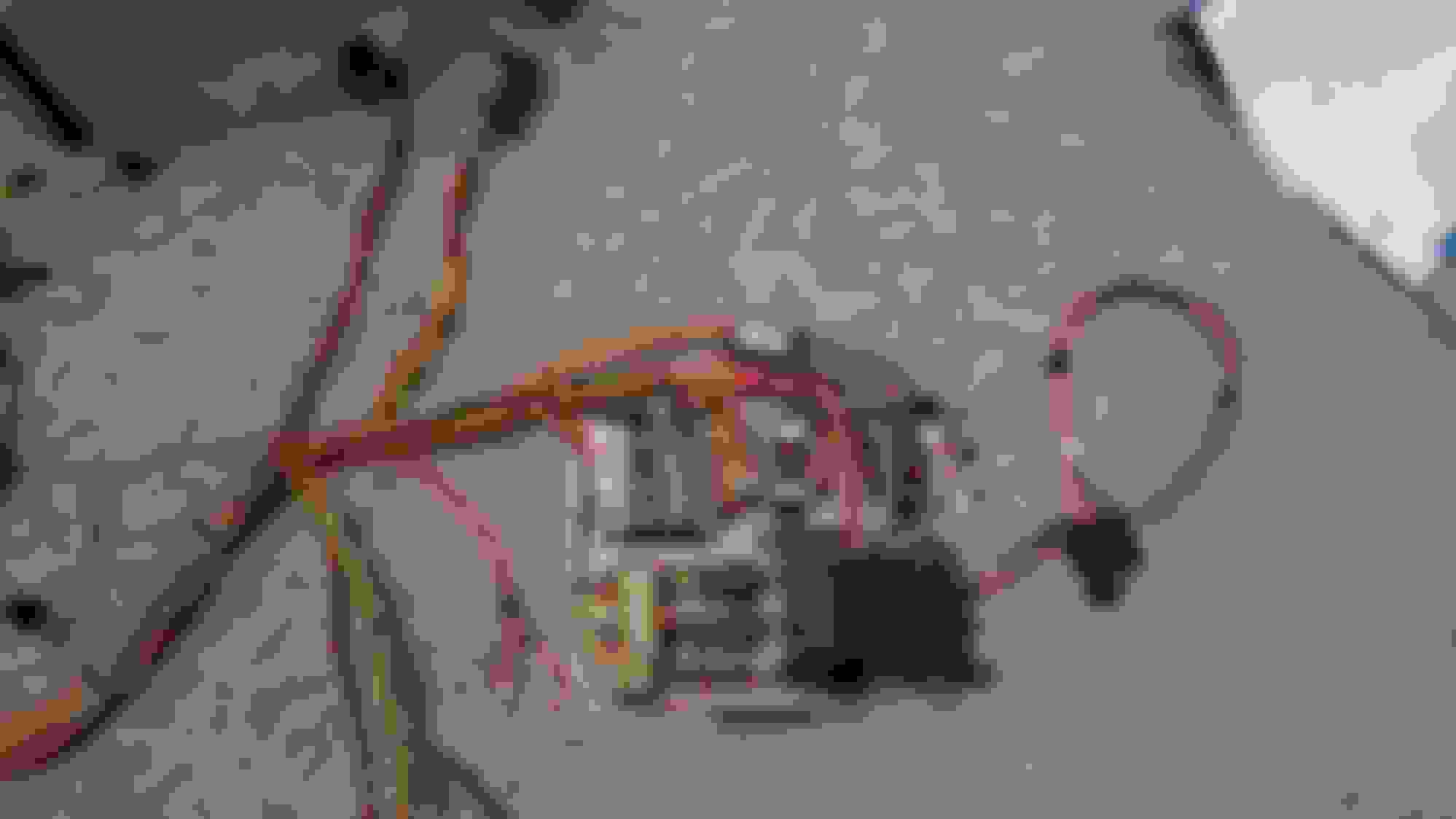
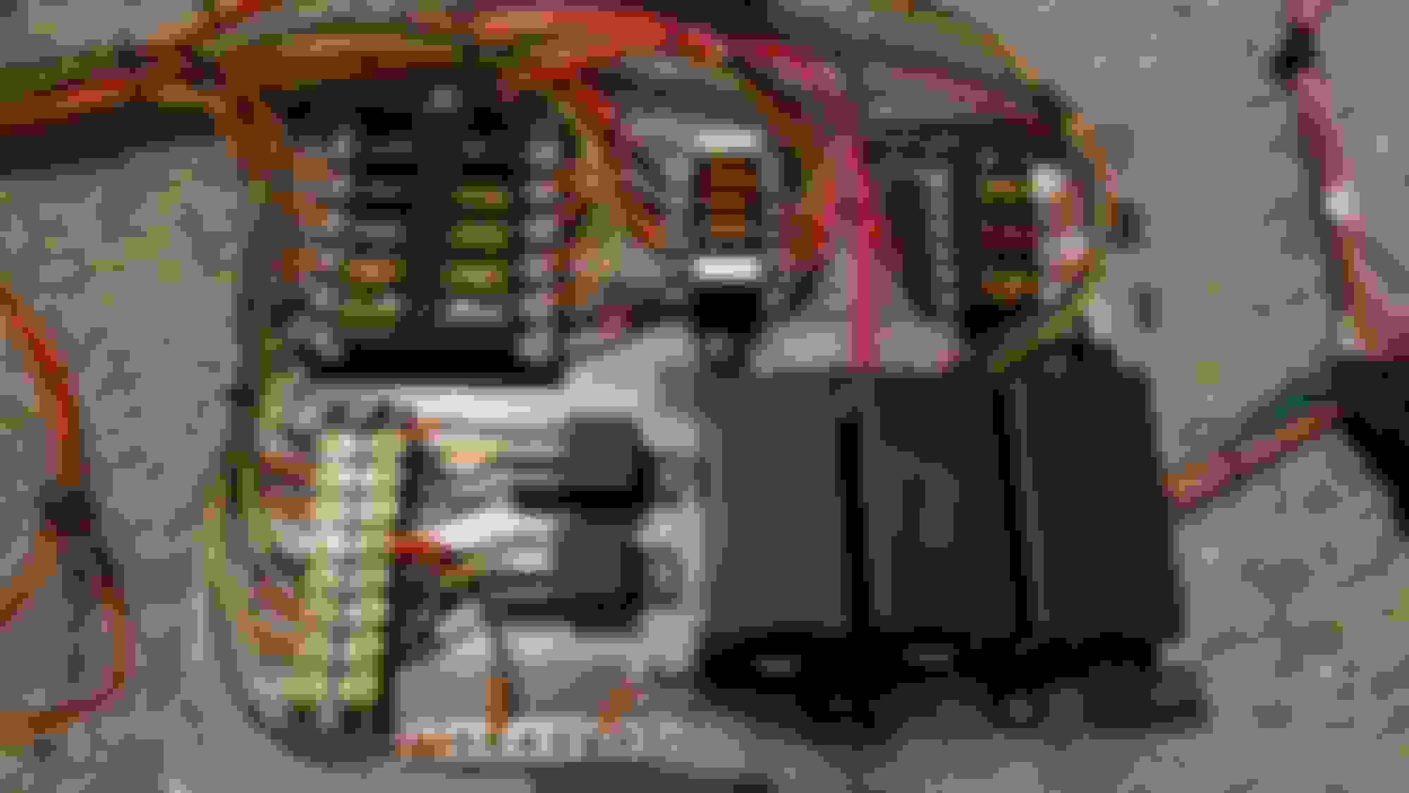
The heart of it all: the main control board. This board replaces the two engine bay fuse boxes as well as the IP fuse box. The fuse panel at top left is all constant +12V, fed from the distribution block mounted below this panel (not shown). The two smaller fuse panels are mixed IGN, ACCY, and RAP, as needed. The relays are for the horn (upper - ground activated) and fog lights (lower - note that it is permanently grounded, so that the fogs remain on regardless of high beam).
This control board is currently mounted floating above a second board containing the PCM, distribution block, and headlight door module in the passenger footwell.
Once I work out all the kinks, the plan is to transfer the entirety of this board (except possibly the ground strip) to a single Bussmann RFRM, which has the capability of supporting up to 40 fuses and 10 relays - more than enough for my needs. I plan to mount that in the void left where the passenger airbag once resided, with some tweaks to make it accessible.
As of right now, almost everything seems to be working except the headlight doors, which I was having trouble with before this process. The motors work when power is applied directly to the connector at the headlight, but not when applied to the connector at the control module, but I can see a jump in voltage at the headlight connector when I switch the headlights on and off, which tells me the module is working. I am thinking that there is simply too much voltage drop between the module and the motors now that the module is inside.
I'd love to hear everyone's feedback/questions. If there's an interest, I'll get more pictures of the installed product.
One other thing I forgot to touch on. I do intend on putting a stereo back in the car eventually, but when I do, it will be with a nice 4-channel amplifier, so the stock wiring was going to be insufficient anyway.
I'm currently going through and taking care of all the warning lights on the gauge cluster. Most are pretty simple, like the "ABS INOP" and "TCS OFF", which just need grounding. One that was troubling me is the "BRAKE" warning light.
The warning light was staying on all the time, so I went about checking the pins at the BMIL driver. I popped it open and removed the simple circuit board so that I could check for ground at the pins, but I was surprised to find that once that board was out, the light worked fine.... so in case anyone was wondering how to go about that.... without the EBCM, the BMIL driver is not needed.
Since I went from auto to manual, I obviously took care of the hatch release circuit by clipping it at S239
Not really. Everything seemed to work pretty reliably for a while, then the car had some mechanical failures, so I've been working on tackling that problem. I've also picked up a different project (DF kit car) which will be more suited as a lightweight, no nonsense speedster, so I'm kind of switching directions on the T/A. Picked up a complete harness (and brake lines, CC, and rear end) from a factory 99+, M6, 3-channel ABS car, so I'll be going back mostly stock in the wiring and tubing department. If you have any questions about the setup as it is now though, I should be able to help out.
 11-11-2016, 10:05 AM