
 04-29-2016, 05:39 PM
Last edit by: IB Advertising
See related guides and technical advice from our community experts:
- Camaro and Firebird How to Add AUX Input MP3 Player without Adapter<br>Step by step instructions for do-it-yourself repairs.

How you can add an aux input/mp3 player without an adapter

 08-28-2007, 09:24 PM
#43
Launching!
Thread Starter

I had it marked as the colored wire on the connector, but I think from now on I'd just find a good spot on the case to connect to it instead ... twist it through a hole somewhere and solder it. A screw would be okay if it's making contact with the chassis
08-28-2007, 10:20 PM
#44
TECH Junkie
iTrader: (1)
Join Date: Nov 2004
Location: TX
Posts: 3,215
Likes: 0
Received 0 Likes
on
0 Posts

Heres what i found on a 2000 Camaro Monsoon,,,, if you notice there are two black wires on each end... i just followed your pics and the one on the left is the left audio...
im just gonna solder the ground to the chasis of the HU....
im just gonna solder the ground to the chasis of the HU....
 08-28-2007, 11:12 PM
#47
TECH Junkie
iTrader: (1)
Join Date: Nov 2004
Location: TX
Posts: 3,215
Likes: 0
Received 0 Likes
on
0 Posts
This is the second time i have ever used a soldering iron.... Plus i'm doing it for free for a friend, so he shouldnt complain as long as it works 
i can handle a 7018 or 6010 stick rod.... look like a row of nickels.... lol
i can handle a 7018 or 6010 stick rod.... look like a row of nickels.... lol
08-29-2007, 01:30 AM
#48
Launching!
Thread Starter
Thanks for the pictures. It was mentioned that the newer units had a different connection but the signal wires were the same, but I've never seen one. Good to see it and have it confirmed, I'm sure they'll help other people.
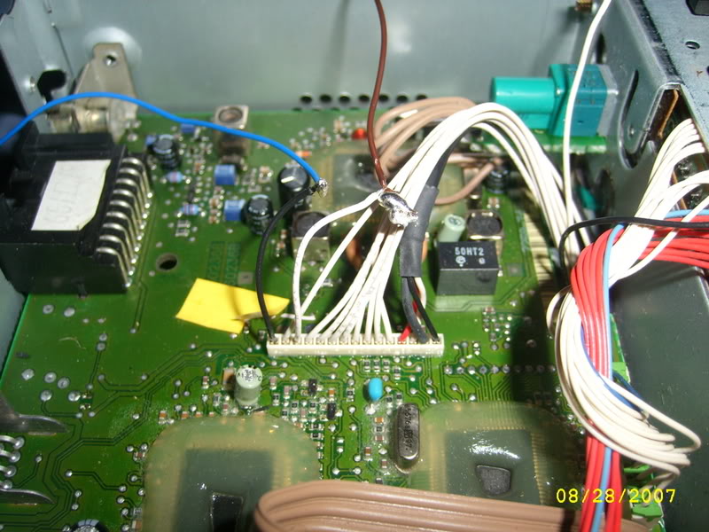
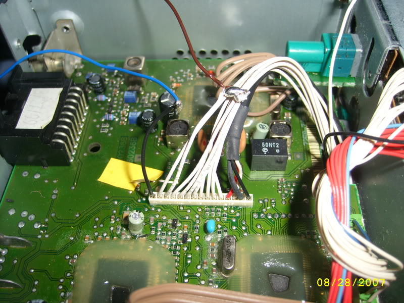
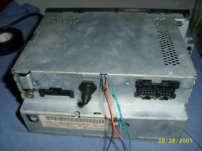
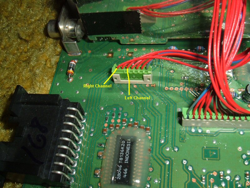
Here are some pics from the install I did on 99'CajunFirehawk157's cassette deck:

There are two connectors, the smaller one has the audio. It's the same two pins, but the channels seem to be reversed. I don't believe the wire on the end is a ground, I grounded it to the chassis.
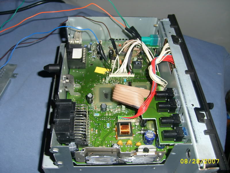
Here it is all done. I drilled a hole in the back and used a grommet, and a big piece of heat shrink tubing on the connector for a cleaner install.

Here are some pics from the install I did on 99'CajunFirehawk157's cassette deck:
There are two connectors, the smaller one has the audio. It's the same two pins, but the channels seem to be reversed. I don't believe the wire on the end is a ground, I grounded it to the chassis.
Here it is all done. I drilled a hole in the back and used a grommet, and a big piece of heat shrink tubing on the connector for a cleaner install.
 09-12-2007, 10:43 AM
#50
TECH Apprentice
iTrader: (2)

Join Date: May 2007
Location: Redding, CA
Posts: 304
Likes: 0
Received 0 Likes
on
0 Posts
I followed all the steps in the write up, the cd player works and sounds fine, but when I go to use the cable and ipod all I hear is terrible feedback and noise?
I haven't tried a different patch cable yet, but the one I have came with an alarm clock ipod radio thing my girlfriend gave me.
I haven't tried a different patch cable yet, but the one I have came with an alarm clock ipod radio thing my girlfriend gave me.
09-12-2007, 12:48 PM
#51
Copy & Paste Moderator
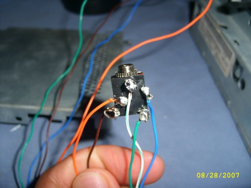
Double check your soldering to make sure none of the blobs are touching. Try to keep the blobs small and neat. Also cover every connection with heat shrink tubing.
Here are a couple soldering tips:
- Put the heat shrink tubing on before soldering
(I've forgotten before and had to do the connection again)
- Use thin rosin-core solder, not plumbing solder
(plumbing solder is too thick for delicate work and its make-up is not appropriate for electrical connections, it can damage the connection over time)
- When soldering, heat up the connection and touch the solder to it. This will draw the solder into the connection making a stronger, smaller, and more conductive connection.
- "Tin" the wires before soldering them into a board or terminal. Tinning is the process of applying a coating of solder to the bare wire end. This will allow you to make the board or terminal connection faster and neater with less heat. Unless its a crimp connection that you are soldering. In which case, crimp then solder (no tinning).
- A good solder connection will be shiny and smooth.
Last edited by VIP1; 09-12-2007 at 12:56 PM.
 09-12-2007, 05:40 PM
#53
Launching!
Thread Starter
bdrussell:
If you can't hear any sound at all it may be a connection issue, though some of it must be good if the CD player still works. It's possibly the audio cable. If you open it back up check all the connections are good and on the correct terminals. You can try hooking up the ground to the chassis instead.
pentavolvo:
Is that the voice of experience?
09-13-2007, 12:03 AM
#54
Yup voice of experience first time I did it on a C5 Vette radio for my dad I had a rag there and everything in case solder dripped as I lifted the iron away some solder fell onto the board, a dead radio later lol. But it does work on the vette radios, and prly most other GM radios
09-17-2007, 05:47 PM
#55
TECH Addict

do you think the same concept could work on a aftermarket deck that uses a cd changer.
I have a 10 year old alpine and I never use the changer. You have me wondering if I can build something to plug into the cable that goes to the changer and plug in, in this case, my satellite radio vs using the FM modulator.
In theory it seems like it should work, just need to find the wires that pass the audio portion of the signal.
hmmmmmmmmm
great post!
09-17-2007, 06:18 PM
#56
Launching!
Thread Starter
If you have a changer, then you should be able to tap into the harness using the same principles. It most likely needs a changer and to be playing since the head unit won't accept audio unless they've talked to each other. It may be possible to do it directly within the head unit, too. The key is the CD/cassette unit is a separate module, so you can easily intercept the audio. I haven't really looked inside a lot of aftermarket units, but it makes sense it would be this way since that's the part most likely to wear out and need to be replaced/serviced while the rest of the unit is fine. It becomes more difficult when the components are integrated into the main circuit board, like the fm radio, so it's not obvious where the audio is.
09-17-2007, 07:00 PM
#57
Copy & Paste Moderator
Or you can get a $15 adapter for the Alpine:
http://www.myradiostore.com/auxadapt...put-am-alpine/
At that point its cheap enough to not bother hacking into it.
http://www.myradiostore.com/auxadapt...put-am-alpine/
At that point its cheap enough to not bother hacking into it.
09-18-2007, 09:16 AM
#58
Launching!
iTrader: (5)
Join Date: Nov 2006
Location: Syracuse NY
Posts: 244
Likes: 0
Received 0 Likes
on
0 Posts
OK, I am confused (which isn't unusual for me).....you tap into the cd player wiring, and a cd phas to be playing in order to use the mp3 player....right? Does the CD player still work? How is that you don't hear both the CD and MP3 player at the same time?
It doesn't look like I can do this mod. I opened up my HU, and it's very much like Firehawk's in his first posts....with the very thin, flat ribbon cable.
It doesn't look like I can do this mod. I opened up my HU, and it's very much like Firehawk's in his first posts....with the very thin, flat ribbon cable.
Last edited by rmpitzer; 09-18-2007 at 12:30 PM.
09-18-2007, 12:56 PM
#59
Copy & Paste Moderator
Originally Posted by rmpitzer
you tap into the cd player wiring
Originally Posted by rmpitzer
and a cd has to be playing in order to use the mp3 player
Originally Posted by rmpitzer
Does the CD player still work?
Originally Posted by rmpitzer
How is that you don't hear both the CD and MP3 player at the same time?
Last edited by VIP1; 09-18-2007 at 01:04 PM.
09-18-2007, 12:58 PM
#60
Launching!
iTrader: (5)
Join Date: Nov 2006
Location: Syracuse NY
Posts: 244
Likes: 0
Received 0 Likes
on
0 Posts
Originally Posted by VIP1
The headphone jack listed above (which is slightly different than a simple headphone jack), switches which source supplies the sound.
Thanks for the answers!
-Rich