DIY Sheetmetal Intake?
 04-19-2011, 10:46 AM
#1
TECH Fanatic
Thread Starter
iTrader: (4)
Join Date: Jul 2007
Posts: 1,572
Likes: 0
Received 0 Likes
on
0 Posts
Has anyone here built their own sheet metal intake from scratch? Ive been watching a few videos on how to do it and the construction loos super simple. Its such an upgrade aesthetics wise and it seems to add some power if you stick with small runners and a 2.5% bend if possible, but most people just use straight pipes.
Only thing im curious about, what are the requirements? I mean does there have to be a certain amount of volume in the intake chamber? The part that the runners connect to. Or do you just have to make sure it can supply enough ait for the runners to draw from? Anyone out there that ever done it, or anyone that can supply a walk through id appreciate it, im more curious than anything but if i can figure it out id take a stab at it. I can construct it no problem, i just want to make sure i build it correctly t give the engine what it needs.
In the beginning of the video, he says "Once the Plenum Shape, Volume, and design are worked out i make cardboard templates......."
How do you work those things out?
I dont think id make one for any of my LTX LSX cars,not yet anyway, but i just bought an old school Volvo that im going to completely build for fun an i was thinking about dicking around with it and trying my hands at making an intake for it. However, people here are generally more knowledgeable and theres more traffic here than turbobricks, and the eventual goal is to make one for my WS6 or even design a dual intake/dual MAF TB etc etc way down the line, once i know what im doing. Mainly for fun if anyone asks. I know there is a dual intake manifold design for the LSX from Australia i am trying to find just to see what they did. EDIT:http://www.google.com/imgres?imgurl=...1t:429,r:2,s:0
http://www.youtube.com/watch?v=R0LM7qMAVr8
Last edited by evilZO6; 04-19-2011 at 10:52 AM.
 04-19-2011, 10:23 PM
#2
With an engineering degree and a flow bench, not a DIY video on YouTube.
If you want examples of sheetmetal intakes, look at these from the master.
Mike
If you want examples of sheetmetal intakes, look at these from the master.
Mike
 04-23-2011, 07:33 PM
#4
TECH Regular
iTrader: (2)

Join Date: Oct 2010
Location: Denver, CO.
Posts: 430
Likes: 0
Received 0 Likes
on
0 Posts

Your PLENUM, or "intake chamber" as you called it, should be at least the same displacement as the engine.
Your runners should have a 1.5 degree taper to them.
Short runners equal more top end power. Long runners equal more low end torque. You can tune these to an rpm range on your engine using different lengths, just like your exhaust runners on headers. It involves knowing the speed of sound.
The inlet on your intake runners should have a "bell mouth" with a radius that is 1.5 times that of the intake runner diameter. Typically you can purchase these online at places like Ross machining or a dozen other's.
You do not need an engineering degree to make your own intake manifold. You just need to do research, and know how to weld. DON'T MIG your intake manifold, unless you are 100% confident that you can mig it with ZERO leaks. 99.9% of the time, intakes are TIG'd together.
Using cardboard for templates is an EXCELLENT way to save time and money on materials. If you **** up cardboard, it's no big deal.
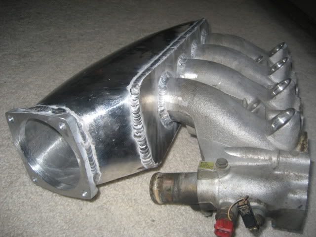
I make intakes for the z31 series 300zx cars. I port and polish the bottom manifold to the 1.5 degree taper (which is actually comes with from the factory) then I weld an aluminum plenum in either 3 or 6 liters on the top of it.
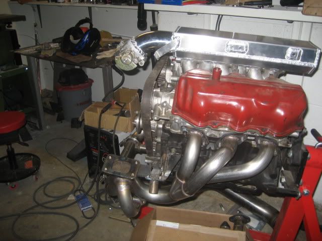
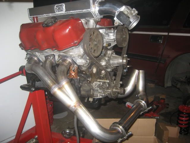
Here is one I did for my buddies 240sx. Notice the bell mouth inlets. I made these by stacking dimes over and over, then shaping them to what they needed to be. They are not the ideal 1.5 times radius of the diameter of the runner. However, they are a hell of a lot better than 90 degree corners LOL.

Your runners should have a 1.5 degree taper to them.
Short runners equal more top end power. Long runners equal more low end torque. You can tune these to an rpm range on your engine using different lengths, just like your exhaust runners on headers. It involves knowing the speed of sound.
The inlet on your intake runners should have a "bell mouth" with a radius that is 1.5 times that of the intake runner diameter. Typically you can purchase these online at places like Ross machining or a dozen other's.
You do not need an engineering degree to make your own intake manifold. You just need to do research, and know how to weld. DON'T MIG your intake manifold, unless you are 100% confident that you can mig it with ZERO leaks. 99.9% of the time, intakes are TIG'd together.
Using cardboard for templates is an EXCELLENT way to save time and money on materials. If you **** up cardboard, it's no big deal.
I make intakes for the z31 series 300zx cars. I port and polish the bottom manifold to the 1.5 degree taper (which is actually comes with from the factory) then I weld an aluminum plenum in either 3 or 6 liters on the top of it.
Here is one I did for my buddies 240sx. Notice the bell mouth inlets. I made these by stacking dimes over and over, then shaping them to what they needed to be. They are not the ideal 1.5 times radius of the diameter of the runner. However, they are a hell of a lot better than 90 degree corners LOL.
04-25-2011, 08:01 PM
#5
TECH Apprentice
iTrader: (6)
Join Date: May 2003
Location: Fairfax County, VA (You know you're here when you see the bad roads)
Posts: 377
Likes: 0
Received 0 Likes
on
0 Posts

if you want to build one just to do it and say you made it yourself....I say go for it! But if its to save money Id have to say just go buy one....youre sure to mess up a few times before getting it right and youll spend lots of time and cash on materials. On the other hand if you buy one you wont learn a thing. Building one will teach you a lot, even if it sucks. fwiw speedy metals website is the cheapest Ive found for raw materials.
04-26-2011, 11:07 PM
#6
TECH Fanatic
Thread Starter
iTrader: (4)
Join Date: Jul 2007
Posts: 1,572
Likes: 0
Received 0 Likes
on
0 Posts
Your PLENUM, or "intake chamber" as you called it, should be at least the same displacement as the engine.
Your runners should have a 1.5 degree taper to them.
Short runners equal more top end power. Long runners equal more low end torque. You can tune these to an rpm range on your engine using different lengths, just like your exhaust runners on headers. It involves knowing the speed of sound.
The inlet on your intake runners should have a "bell mouth" with a radius that is 1.5 times that of the intake runner diameter. Typically you can purchase these online at places like Ross machining or a dozen other's.
You do not need an engineering degree to make your own intake manifold. You just need to do research, and know how to weld. DON'T MIG your intake manifold, unless you are 100% confident that you can mig it with ZERO leaks. 99.9% of the time, intakes are TIG'd together.
Using cardboard for templates is an EXCELLENT way to save time and money on materials. If you **** up cardboard, it's no big deal.
I make intakes for the z31 series 300zx cars. I port and polish the bottom manifold to the 1.5 degree taper (which is actually comes with from the factory) then I weld an aluminum plenum in either 3 or 6 liters on the top of it.
Here is one I did for my buddies 240sx. Notice the bell mouth inlets. I made these by stacking dimes over and over, then shaping them to what they needed to be. They are not the ideal 1.5 times radius of the diameter of the runner. However, they are a hell of a lot better than 90 degree corners LOL.
1) 1.3-1.5x engine displacement=Plenum Volume
2) 2 degree taper is best but straight does ok too
3)TIG weld dont MIG weld
4)cardboard first, metal later
5)meth injection is easily integrated and generally works better than fogging
im ready to start farting around with it. Volvo b21ffirst, maybe WS6 much later lol but if i do it im doing a twin plenum cross runner with dual TB
Trending Topics
 04-28-2011, 10:14 PM
#9
TECH Regular
iTrader: (2)
Join Date: Oct 2010
Location: Denver, CO.
Posts: 430
Likes: 0
Received 0 Likes
on
0 Posts
Do you just mean runners with a taper to them? Generally, the taper is there to allow as much air to enter the runner as possible at first. Then as the runner tapers down in size, it causes air velocity to speed up, thus increasing torque.
04-29-2011, 09:36 PM
#10
Staging Lane

Join Date: Sep 2010
Location: Santa Cruz
Posts: 83
Likes: 0
Received 0 Likes
on
0 Posts
Im working on one right now and have these questions;
if the runners are larger than the ports then what happens at the flange? is there a step inside the runner?
on factory intakes the ports are pretty matched so it stand to reson the flange should be similar to that right?
would there be any benefit/loss from having the flange opening at the head the same as the runner at that point? (1/8-1/4" wider then factory) thats how I'd like to do it so ported heads will work well. thanks in advance.
Last edited by inde-fab; 04-29-2011 at 09:47 PM.
04-29-2011, 11:04 PM
#11
TECH Regular
iTrader: (2)
Join Date: Oct 2010
Location: Denver, CO.
Posts: 430
Likes: 0
Received 0 Likes
on
0 Posts
Im working on one right now and have these questions;
if the runners are larger than the ports then what happens at the flange? is there a step inside the runner?
on factory intakes the ports are pretty matched so it stand to reson the flange should be similar to that right?
would there be any benefit/loss from having the flange opening at the head the same as the runner at that point? (1/8-1/4" wider then factory) thats how I'd like to do it so ported heads will work well. thanks in advance.
if the runners are larger than the ports then what happens at the flange? is there a step inside the runner?
on factory intakes the ports are pretty matched so it stand to reson the flange should be similar to that right?
would there be any benefit/loss from having the flange opening at the head the same as the runner at that point? (1/8-1/4" wider then factory) thats how I'd like to do it so ported heads will work well. thanks in advance.
Flow can always step out, but should never STEP in. In an intake runner it can TAPER in, but not step in. Taper increases velocity. However, A step just creates a lip for air to essentially trip over and cause turbulence. It is this reason that port and gasket matching is so important.
04-30-2011, 12:11 AM
#12
Staging Lane
Join Date: Sep 2010
Location: Santa Cruz
Posts: 83
Likes: 0
Received 0 Likes
on
0 Posts
okay that was the logic I had originally come up with. after looking at so many other designs it just seemed like alot of the runners are wider then mine will be, maybe they are thicker. Thanks for the quick reply satan, this really helps since I'm gonna try to get the flanges made up tomorrow. I guess a cork gasket is the best option for now? at least until I can get the factory rubber rings worked into the design. is there something re-useable out there?
 05-06-2011, 12:44 AM
#14
Staging Lane
Join Date: Sep 2010
Location: Santa Cruz
Posts: 83
Likes: 0
Received 0 Likes
on
0 Posts
is there a linear logic or equation for runner volume or shape?
I understand longer runners are better for lower rpm/flatter power curve and shorter runners are better for top-end but is there an actual way to design a runner based on the intended motor combo?
I understand longer runners are better for lower rpm/flatter power curve and shorter runners are better for top-end but is there an actual way to design a runner based on the intended motor combo?
05-06-2011, 01:57 AM
#15
TECH Veteran
iTrader: (12)
Join Date: Dec 2004
Location: Rockville, MD
Posts: 4,354
Likes: 0
Received 0 Likes
on
0 Posts
i think.. if you have the info for the taper and opening sizes you go to runner length based on what RPM range you will be using. from there i guess its more up to you how to design the plenum box and all that good stuff. as one of LStechs members always says... think like air.
05-07-2011, 04:24 PM
#16
satan,1.5* taper is not some magic number that works... the greater the taper the greater the ram tuning effect that the runners are going to have. OTOH, the greater the taper the less effect the harmonic length tuning will have (typically it's the strongest with no taper). To compute the harmonic length of the runners for a specific rpm range you basically need to compute the Helmholtz frequency for the column of air in that runner and convert that number to an rpm.
I suspect from the pictures that you've posted that you're wasting your time with the 1.5* taper, that you don't have a long enough runner length to tune for an appropriate rpm and you'd make more power with something in the 3-5* taper range...
I suspect from the pictures that you've posted that you're wasting your time with the 1.5* taper, that you don't have a long enough runner length to tune for an appropriate rpm and you'd make more power with something in the 3-5* taper range...
05-07-2011, 11:50 PM
#17
Staging Lane
Join Date: Sep 2010
Location: Santa Cruz
Posts: 83
Likes: 0
Received 0 Likes
on
0 Posts
^thats probobly appropriate for the high rpm setup.
I am working on designing runner extensions of various lengths to the inside of the plenum for testing. hopefully gaining a little better torque and midrange power over the stock ls6 intake with some top end gains too. <I know no small order...
any ideas on a decent runner length to start with for that kind of goal in mind?
I decided to go with approximately 550ci for the plenum to begin with, as the runners get longer the volume will decrease, which I believe is appropriate for tuning to specific rpms. please please correct me if I'm wrong.
got the short runners shaped out, they came out to be about 4.5" long in the center. Given the nature of harmonics I realized today I prob. want the ports more squared at the plenum side, so the extensions will be, but you get the basic idea of the shape
input please
06-06-2011, 01:01 PM
#18
TECH Apprentice

Join Date: Jun 2007
Posts: 364
Likes: 0
Received 0 Likes
on
0 Posts
Pipemax software will you give the full runner length calculation. This INCLUDES the head runner length.
It will also give you the best selection for header tubes amongst other accurate calculations.
It will also give you the best selection for header tubes amongst other accurate calculations.
06-06-2011, 02:59 PM
#19
All it's doing is calculating the frequency that it takes to for the wave to get to either end of the tube (one time is the first order, there and back is the second order... pulses past the 3rd order are too weak to care about), then you just figure out the the size of the column of air that tunes for the frequency, which is the same equation that you use to calculate port sizes for speaker ports (remember that the ports in the head have a length and volume that adds to the intake runner)...
06-06-2011, 07:30 PM
#20
TECH Apprentice
Join Date: Jun 2007
Posts: 364
Likes: 0
Received 0 Likes
on
0 Posts
All it's doing is calculating the frequency that it takes to for the wave to get to either end of the tube (one time is the first order, there and back is the second order... pulses past the 3rd order are too weak to care about), then you just figure out the the size of the column of air that tunes for the frequency, which is the same equation that you use to calculate port sizes for speaker ports (remember that the ports in the head have a length and volume that adds to the intake runner)...
It is a pretty complex calculation.
Inde-fab- are those runners made of wood?
If so, do you plan on wrapping sheet metal around them to form the runner?
Last edited by ponjohn; 06-06-2011 at 07:36 PM.

